4.3.28.1. Bootloader User Guide
Introduction to Bootloader
In embedded Linux systems, the Bootloader (Boot Loader) is a critical component responsible for hardware initialization, operating system loading, and security verification. Its main functions include:
Hardware Initialization: Configure fundamental hardware settings such as CPU clock frequency and memory controller to ensure the system enters a stable operating state at startup.
Operating System Loading: Load the Linux kernel image (typically in compressed format) from storage media (e.g., NAND Flash, eMMC, SD card), then transfer control to the kernel entry point.
Security Verification: Verify firmware integrity and authenticity using CRC checks, digital signatures, or hash algorithms (e.g., SHA-256) to prevent injection of malicious code.
Passing Boot Parameters: The bootloader passes essential boot parameters (such as memory size, CPU architecture information, and kernel command-line arguments) to the Linux kernel, ensuring smooth kernel startup and execution.
U-Boot (Universal Bootloader) is the most widely used bootloader in embedded Linux systems, offering highly flexible configuration options and support for multiple hardware platforms and storage media.
Note: In this system, the entire bootloader is divided into the following stages:
BL1: Bootloader Level 1, a program stored in the chip’s IROM, also known as Bootrom, primarily responsible for initializing basic hardware functions.
BL2: Bootloader Level 2, the second stage of the bootloader, mainly responsible for hardware initialization and security verification.
BL31: Bootloader Level 3_1, primarily executing security-related operations.
BL33/U-Boot: Bootloader Level 3_3; in this system, BL33 refers to the general U-Boot.
This boot process follows the typical multi-stage boot design in ARM’s Trusted Firmware (TF) architecture, enabling secure boot and hardware isolation.
Special Note:
In this document, bootloader refers to the entire boot loader, while U-Boot specifically refers to the BL33 stage in the bootloader process, i.e., U-Boot.
Bootloader Configuration and Compilation
In this system, users generally only need to focus on U-Boot stage configuration. For details, refer to the Configure U-Boot Options section.
After configuration, use the following commands to compile or clean the bootloader image:
# Compile U-Boot separately
./bd.sh uboot
# Clean U-Boot separately
./bd.sh uboot clean
# Distclean U-Boot separately
./bd.sh uboot distclean
For detailed information about image compilation, refer to the Compilation Process and Commands section.
Key Bootloader Files
Below are the key bootloader files in the BSP source package.
Configuration Files
# Configuration file directory
uboot/configs
# X5-related configuration files
hobot_x5_auto_defconfig
hobot_x5_evb_nand_defconfig
hobot_x5_fpga_defconfig
hobot_x5_soc_defconfig
hobot_x5_svb_defconfig
hobot_x5_svb_nand_defconfig
The board-level configuration file device/horizon/x5/board_xxx_config.mk specifies the configuration file used by U-Boot. For more details on board-level configuration files, refer to the U-Boot Option Configuration section.
Device Tree Files
# Device tree file directory
uboot/arch/arm/dts/x5.dtsi/
# X5-related device tree files
hobot-x5.dts
x5-fpga.dtsi
x5-soc.dtsi
x5-svb.dtsi
x5.dtsi
x5-rdk.dtsi
pinmux-func.dtsi
For instructions on adding new device tree files under U-Boot, refer to the Adding Device Tree in U-Boot section.
Platform-Specific Files
# Platform chip hardware abstraction layer directory
uboot/arch/arm/mach-horizon
# Includes the following files
├── Kconfig
├── Makefile
├── lowlevel_init.S
└── x5
    ├── Kconfig
    ├── Makefile
    ├── boot_info.c
    ├── cpu.c
    ├── fdt_setup.c
    ├── x5_board.c
    ├── x5_efuse.c
    ├── x5_ion_setup.c
    └── x5_rpmb.c
The uboot/arch/arm/mach-horizon/x5 directory contains hardware abstraction layer files specific to the X5 chip. These codes directly manipulate internal chip registers and are among the earliest modules executed during boot, ensuring correct initialization of chip hardware resources.
# Platform hardware configuration file directory
uboot/board/horizon/
# Includes the following files
├── common
│   ├── Makefile
│   ├── hb_sdhc_boot.c
│   └── horizon_dfu.c
└── x5
    ├── MAINTAINERS
    ├── Makefile
    ├── spi.c
    ├── x5-aarch32.its
    ├── x5.c
    └── x5.its
The uboot/board/horizon/x5 directory contains hardware configuration files for the X5 chip, responsible for board-level support, including maintainer information, build configuration, SPI driver, board initialization code, and configuration files required for generating boot images.
Bootloader Boot Process
Analysis of Bootloader Boot Flow
The bootloader boot flow on the X5 platform is as follows:
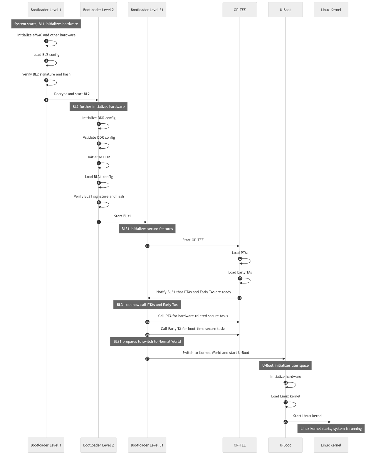
Overview of Bootloader Boot Process:
BL1 Stage (Bootloader Level 1):
This stage initializes basic hardware functions, checks eMMC configuration, and loads the BL2 configuration file. During this process, BL1 verifies the signature and hash value of BL2 to ensure firmware integrity and origin. Upon successful verification, BL1 decrypts and starts BL2.BL2 Stage (Bootloader Level 2):
BL2 continues hardware initialization, especially DDR configuration, loads DDR configuration files, and performs hash validation. After DDR initialization, BL2 loads and verifies the signature and hash value of the BL31 configuration file to ensure its security. Upon successful verification, BL2 starts BL31.
Entering Secure World: After BL2 starts BL31, the system enters the Secure World, preparing to execute security-related initialization tasks.BL31 Stage (Bootloader Level 31):
BL31 is responsible for initializing security features and launching OP-TEE (Open Portable Trusted Execution Environment). After OP-TEE completes secure environment initialization, control returns to BL31, which executes security-related tasks via PTA (Pseudo Trusted Application) and ETA (Early Trusted Application).
Secure World Operations: BL31 and OP-TEE run entirely within the Secure World, ensuring the security of the entire boot process.OP-TEE Stage:
This stage loads OP-TEE’s PTA and Early TA, providing secure services such as encryption and key management. All operations are performed within the Secure World, ensuring isolation and security of security tasks.Switching to Normal World:
After BL31 completes security tasks, the system prepares to switch to the Normal World. BL31 transfers control to U-Boot, completing the transition from Secure World to Normal World. This process is achieved through mechanisms provided by TrustZone, ensuring isolation between Secure and Normal Worlds.U-Boot Stage:
After BL31 finishes its work, control is transferred to U-Boot. U-Boot’s main responsibilities include loading and verifying the Linux operating system and initializing the user-space environment, including hardware initialization and preparation of user interaction interfaces. After mounting Linux system partitions, U-Boot begins executing user-space code.
Normal World Operations: U-Boot and the subsequent Linux kernel run in the Normal World, handling regular system functions and user interactions.Linux Kernel Startup:
Finally, U-Boot boots the Linux kernel, completing the system startup process. The Linux kernel runs in the Normal World, managing system resources and executing user applications.
Key Function Analysis in Bootloader Boot Flow
Entry Function _start
_start is located at uboot/arch/arm/cpu/armv8/start.S, and is the first piece of assembly code executed after hardware boot, responsible for low-level initialization:
Code and BSS Segment Setup: Initialize
.text(code segment),.data(data segment), and zero out.bss(uninitialized global variables).Exception Vector Table Setup: Define the ARMv8 interrupt vector table to ensure correct jump to handlers when exceptions occur.
CPU Mode Switching: Switch from the default exception mode in BootROM (e.g., EL3/EL2) to the privilege mode used by the OS (e.g., EL1).
Main flow of _start function:
_start
├─> reset
│    ├─> save_boot_params (board-specific)
│    ├─> PIC Fixup (position-independent handling)
│    ├─> Set VBAR (exception vectors)
│    ├─> EL level configuration (enable FP/SIMD/interrupts)
│    ├─> SMPEN/errata handling
│    ├─> lowlevel_init
│    │    ├─> GIC initialization (primary core)
│    │    └─> Multi-core wake-up/wait logic
│    └─> Jump to _main (C entry point)
└─> Secondary core logic (slave_cpu)
     └─> wfe loop until primary core releases
_main
The _main function is located in uboot/arch/arm/lib/crt0_64.S. crt0_64.S is U-Boot’s startup code for the AArch64 architecture, responsible for setting up the C runtime environment and jumping into C functions board_init_f and board_init_r to complete initialization at different stages.
The _main function is primarily responsible for:
Setting up the initial runtime environment, preparing the stack and initializing global data (GD).
Calling
board_init_f()to initialize hardware.Enabling debug serial port (optional).
Setting up intermediate environment and performing code relocation (U-Boot only, not SPL).
Preparing the final environment and calling
board_init_r().
Execution flow of _main function:
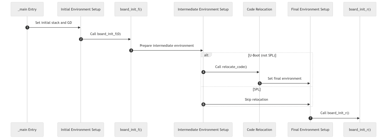
Detailed explanation:
Entry (
_main Entry):Entry point of the
_mainfunction, starting the entire boot process.
Initial Environment Setup (
Initial Environment Setup):Set up initial stack and global data structure (GD), preparing the environment for calling
board_init_f().
Call
board_init_f():Call the
board_init_f()function to prepare the hardware environment for running in system RAM.
Intermediate Environment Setup (
Intermediate Environment Setup):Update stack and GD based on results from
board_init_f().
Code Relocation (
Code Relocation):If U-Boot (not SPL), call
relocate_code()to move U-Boot code to the target address.
Final Environment Setup (
Final Environment Setup):Set up the final runtime environment, including initializing BSS and non-constant data.
Call
board_init_r():Jump to
board_init_r(), entering the next phase.
Branch Explanation:
Difference between U-Boot and SPL:
For U-Boot, code relocation is performed.
For SPL (Secondary Program Loader), relocation is skipped, directly proceeding to final environment setup.
board_init_f
The board_init_f function is located in uboot/common/board_f.c, executing functions defined in the init_sequence_f array. Only key functions are listed below:
static const init_fnc_t init_sequence_f[] = {
	initf_malloc,		/* Early heap initialization */
	arch_cpu_init,		/* SoC initialization for each architecture */
	board_early_init_f 	/* Board-level early initialization function */
	serial_init,		/* Serial port initialization */
	dram_init,		/* Configure DDR size */
	reserve_round_4k,	/* Reserve various regions, prepare for relocation */
	arch_reserve_mmu,
	reserve_video,
	reserve_trace,
	reserve_uboot,
	reserve_malloc,
	reserve_board,
	reserve_global_data,
	reserve_fdt,
	reserve_bootstage,
	reserve_bloblist,
	reserve_arch,
	reserve_stacks,
	dram_init_banksize,	/* Initialize sizes of each bank in global data */
	show_dram_config,
	INIT_FUNC_WATCHDOG_RESET
	setup_bdinfo,
	display_new_sp,
	INIT_FUNC_WATCHDOG_RESET
	reloc_fdt,
	reloc_bootstage,
	reloc_bloblist,
	setup_reloc,		/* Determine relocation address */
	clear_bss,
	NULL,
};
After executing these functions, early hardware configuration and memory reservation processes are successfully completed.
board_init_r
The board_init_r function is located in common/board_r.c, executing functions in the init_sequence_r array. Only key parts are listed:
static init_fnc_t init_sequence_r[] = {
	initr_caches,		/* Initialize cache and MMU */
	initr_malloc,		/* Initialize heap area */
	initr_of_live,
	initr_dm,		/* Initialize DM framework */

	board_init,		/* Board-level initialization function */
	initr_watchdog,		/* Initialize watchdog */
	last_stage_init,	/* Final stage initialization before main_loop; checks boot modes and sets wake variables */
	run_main_loop,		/* Enter final loop stage, command line mode, or execute boot command */
};
Key Sub-function Descriptions:
initr_caches: Enable CPU cache and MMU (Memory Management Unit) to improve execution efficiency and memory protection.initr_dm: Initialize the device model (Driver Model), scan the device tree (DTB), and load matching drivers.board_init: Initialize board peripherals (e.g., GPIO, Ethernet PHY, storage interfaces).last_stage_init: Determine boot mode (e.g., normal boot, recovery mode, network boot) based on environment variables or hardware pin states, and setbootcmdexecution target.run_main_loop: Enter U-Boot command line or automatically executebootcmd(e.g., load kernel, boot OS).
After executing these functions, late-stage advanced feature initialization is completed, and the system is ready to enter the main loop.
Introduction to Secure Boot Process
Secure Boot is a crucial mechanism ensuring the integrity and trustworthiness of firmware and software during system startup. Throughout the bootloader boot process, secure boot is based on the Root of Trust, verifying boot images level by level to achieve trusted firmware loading.
The Secure Boot process in this system is shown below:
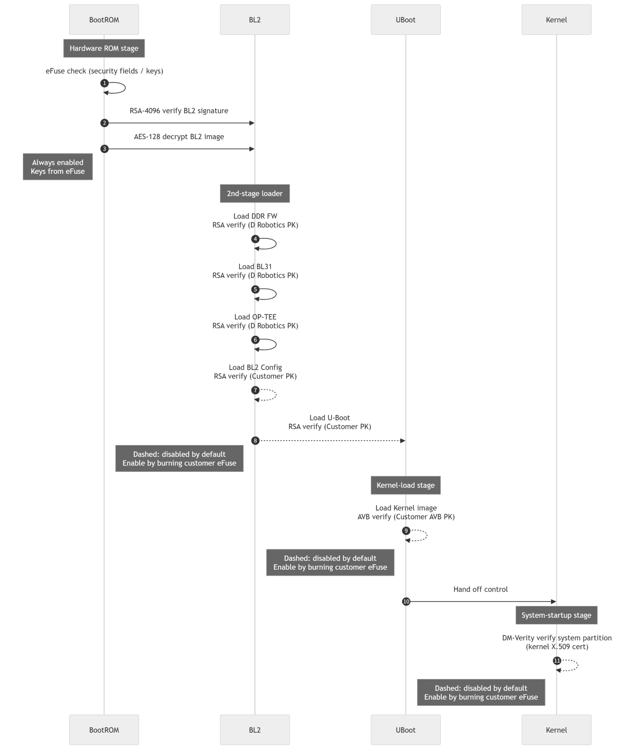
For related secure development content, refer to the Security Development Guide series in this manual.
For detailed information on Secure Boot, refer to the document X5 Secure Boot Overview.
BootROM Stage
Verification Mechanism:
Signature Verification: RSA-4096 (based on public key certificate)
BootROM uses the RSA-4096 public key algorithm to verify the signature of firmware (e.g., BL2). RSA-4096 is a commonly used strong encryption algorithm, sufficient to ensure the security of the verification process. Signature verification ensures firmware content has not been tampered with and originates from a trusted source.
Decryption Algorithm: AES-128 (used for BL2 image decryption)
AES-128 (Advanced Encryption Standard) is used to decrypt the BL2 image. AES-128 is a symmetric encryption algorithm with high security and performance. During boot, AES-128 decryption protects firmware confidentiality, preventing tampering or leakage during transmission.
Certificates/Keys:
Root Public Key: Stored in eFuse, typically a non-modifiable hardware storage area. The root public key allows BootROM to verify BL2’s digital signature. Pre-provisioned root public keys ensure only trusted firmware passes verification.
AES Decryption Key: May also be stored in eFuse or hard-coded in hardware to enhance key protection, ensuring key security and preventing malicious programs from obtaining the key and cracking the firmware.
Default State:
Signature verification and decryption are enabled by default, requiring no customer intervention.
BL2 Stage
Certificate and key information involved in the BL2 stage is shown in the table below:
| Image | Verifier | Certificate Source | Default State |
|---|---|---|---|
| BL31 | D-Robotics | D-Robotics pre-provisioned public key certificate | Enabled by default |
| OP-TEE | D-Robotics | D-Robotics pre-provisioned public key certificate | Enabled by default |
| DDR Firmware | D-Robotics | D-Robotics pre-provisioned public key certificate | Enabled by default |
| U-Boot | Customer | Customer-defined public key certificate | Disabled by default |
| BL2 Config | Customer | Customer-defined public key certificate | Disabled by default |
The main task of the BL2 stage is to verify the integrity and trustworthiness of firmware images, ensuring no malicious code is loaded during boot. All images use RSA signature verification, using pre-provisioned public key certificates to verify firmware legitimacy.
Verification Mechanism: All images use RSA signature verification
Certificates/Keys:
Use the certificates/keys listed in the table above for verification.
Default State:
Disabled by default; verification for U-Boot and BL2 Config requires customers to enable custom public keys by burning eFuse.
Key Operation: Perform hash verification (
verify_hash) before loading BL31 and OP-TEE to ensure image integrity.For detailed information on U-Boot and BL2 Config verification, refer to the U-Boot & BL2 CFG Verification section.
Certificate and Key Management:
At the BL2 stage, D-Robotics provides pre-provisioned public key certificates to verify the integrity of BL31, OP-TEE, and DDR Firmware images.
By default, verification for these images is enabled, ensuring trustworthiness of these critical components.
The system automatically verifies these images during boot to ensure they have not been tampered with.
For U-Boot and BL2 Config images, verification is disabled by default. Customers can enable custom public key certificate verification by burning eFuse according to their needs.
For detailed information on certificates/keys, refer to the Key Management section.
RSA Signature Verification:
All firmware images (including BL31, OP-TEE, DDR Firmware, U-Boot, and BL2 Config) use RSA signature verification.
This mechanism verifies firmware integrity and authenticity through digital signatures, ensuring only unmodified images can be loaded and executed.
With RSA signatures, any unauthorized modification to firmware can be detected during boot, preventing injection of malicious code.
Image Integrity Verification:
Before loading BL31 and OP-TEE images, the system performs hash verification (
verify hash) to ensure the loaded image files have not been tampered with.This verification step is a critical part of the BL2 stage, ensuring image integrity and further enhancing system security.
U-Boot Stage
Verification Mechanism: Android Verified Boot (AVB)
Tools/Algorithms:
Use AVB 2.0 protocol to verify kernel image hash and signature.
Supports RSA-2048/4096 or SHA-256 hash trees.
Certificates/Keys:
Verification chain based on AVB public key burned by customer into eFuse.
Default State:
Disabled by default, requires customer to burn eFuse to enable AVB verification.
For detailed information on U-Boot encryption, refer to the Boot Encryption Introduction document.
Linux Kernel Stage
Verification Mechanism: DM-Verity (Device-Mapper Verity)
Function: Perform integrity verification (anti-tampering) on the
systempartition.Configuration Dependency:
Disabled by default, requires customer to burn eFuse to enable DM-Verity.
Implementation:
After kernel boot, load DM-Verity metadata (hash tree and signature).
Use the public key pre-installed in the kernel keyring (
system_trusted_keyring) to verify the signature.
For detailed information on
AVBandDM-Verity, refer to the Kernel & Rootfs Verification section.
Summary of Security Configuration
| Stage | Verification Tool/Algorithm | Certificate/Key Source | Default State | Enable Condition |
|---|---|---|---|---|
| BootROM | RSA-4096 + AES-128 | eFuse Root Public Key | Enabled | Hard-coded, not alterable |
| BL2 | RSA Signature | D-Robotics/Customer Certificate | Partially Enabled | Customer burns eFuse |
| U-Boot | AVB 2.0 | Customer AVB Public Key | Disabled | Customer burns eFuse |
| Kernel | DM-Verity | Kernel Built-in X.509 Certificate | Disabled | Customer burns eFuse |
Additional Notes:
Tiered Verification in BL2 Stage: D-Robotics’ public key ensures trustworthiness of base firmware (BL31, OP-TEE, DDR FW), while customer public keys are used for business-related modules (U-Boot, BL2 Config), achieving responsibility separation.
Relationship between AVB and FIT Image: U-Boot supports both FIT (Flat Image Tree) image verification (traditional method) and AVB verification; priority for AVB flow must be configured at compile time.
U-Boot Dynamic Configuration of Kernel ION Reserved Memory Size Usage Guide
ION is a memory management framework in the Linux kernel, providing efficient memory pools and memory partitioning mechanisms, particularly suitable for multimedia processing such as graphics and video. For more details on ION, refer to the Default ION Reserved Memory section.
The X5 platform’s U-Boot implements a feature to dynamically modify the kernel ION reserved memory size based on U-Boot internal environment variables. The following table lists the supported kernel ION reserved memory regions and corresponding environment variables:
| U-Boot Environment Variable Name | Kernel ION Region DTS Label | ION Region DTS Compatible String |
|---|---|---|
| ion_reserved_size | ion_reserved | ion-pool |
| ion_carveout_size | ion_carveout | ion-carveout |
| ion_cma_size | ion_cma | ion-cma |
These nodes are defined in the kernel device tree file kernel/arch/arm64/boot/dts/hobot/x5-memory.dtsi.
Usage: After entering the U-Boot command line, use the command:
# Modify ION environment variable
setenv ion_reserved_size 0x40000000
# Save environment variable if persistence across reboots is needed
saveenv
# Boot Linux kernel
boot
# View ION memory in kernel
cd /app/platform_samples/sysinfopro/
./sysinfopro -m
The above command sets the ion_reserved_size environment variable to 0x40000000, modifying the corresponding ION region size to 1GB. Where:
ion_reserved_sizeis the U-Boot environment variable name corresponding to the target ION region to be modified;0x40000000is the desired size for the target ION region.
Example:
# Execute in U-Boot
Hobot>setenv ion_reserved_size 0x40000000
Hobot>boot
# After kernel boots, view ION memory information
root@buildroot:~# cd /app/platform_samples/sysinfopro/
root@buildroot:/app/platform_samples/sysinfopro# ./sysinfopro -m

[Memory Info]:
        [Total Memory]:         1.28 GB
        [Used Memory]:          0.21 GB
        [Free Memory]:          1.02 GB

        [NOTE] What is displayed is the memory available to the system,
        which is the actual physical memory capacity minus ION and system reserved memory.
        (The content is consistent with "free -h")

[ION Memory Info]:
        [ION CMA Memory Size]:          0.50 GB
        [ION Carveout Memory Size]:     1.00 GB
        [ION Reserved Memory Size]:     1.00 GB
As shown, ION Reserved Memory Size is 1GB.
Notes:
Memory Size Limitation: When the total configured ION region size (
ion_reserved_size + ion_carveout_size + ion_cma_size) plus the ION start address and default kernel HEAP size (DEFAULT_KERNEL_MIN_HEAP) exceeds the total available DDR size, U-Boot will issue a warning and automatically reduce the size of these three regions. The reduction unit is 16MiB (total reduction of 48MiB per cycle), until the ION regions fit within the available DDR size.If all regions are reduced to
ION_MIN_SIZE(default 64MiB) and still cannot fit, U-Boot will report an error, but the boot process will not stop.The values of
ION_MIN_SIZEandDEFAULT_KERNEL_MIN_HEAP(default 64MiB) are defined in the filearch/arm/mach-horizon/x5/x5_ion_setup.c.
Hexadecimal Value Requirement: U-Boot environment variables only accept hexadecimal numbers. Using invalid hexadecimal values may cause boot anomalies.
U-Boot Usage Guide for dtb overlay
DTS Overlay is a mechanism that allows dynamic modification of device trees at runtime to support changes in hardware configuration.
The X5 platform’s U-Boot implements a function to perform overlay operations on the kernel DTS based on U-Boot internal environment variables. Users can specify overlay files by setting environment variables. (For more details, refer to Linux Kernel Overlay File Writing Guide).
Note: The DTS Overlay format in the linked document requires dtc tool version 1.5 or higher.
General Rules
Enable Condition: The DTS overlay function is only enabled when the
dtbo_file_pathenvironment variable is configured.File Limitation: Currently, only a single dtbo file is supported for overlay operations.- Default Behavior: By default, the overlay takes effect only once in the current boot session. To keep it effective in subsequent boots, one of the following three methods can be used:
Use the
saveenvcommand to save the current environment variables.During U-Boot compilation, directly set the
dtbo_file_pathenvironment variable in the./include/configs/x5.hfile.Refer to the U-Boot FIT Image DTS Overlay Documentation.
Path Explanation: The paths mentioned in the text refer to paths within a partition. For example, if the partition is mounted at
/userdata, the in-partition path of/userdata/test.dtbois/test.dtbo.
Retrieve Overlay File from Fixed Location
Default Location: On the X5 platform, the overlay file is by default retrieved from the 12th partition of mmc0 (must be formatted as ext4).
Configuration Command: Users need to use the
setenv dtbo_file_path <path to dtbo file>command to configure the environment variable so that the boot process automatically retrieves and uses the overlay file. For example, if the overlay file is located at/test.dtbo, execute:setenv dtbo_file_path /test.dtbo
Complete Configuration of Overlay File Location
The following U-Boot environment variables need to be configured:
| U-Boot Environment Variable | Meaning | Example |
|---|---|---|
| dtbo_fs | File system format of the partition containing the overlay file | ext4 (currently only ext4 is supported) |
| dtbo_dev | Device interface type where the overlay file resides | mmc |
| dtbo_part | Device and partition number where the overlay file resides | 0:c |
| dtbo_file_path | Path within the partition where the overlay file is located, with the partition itself as the root directory | /test.dtbo |
| dtbo_load_addr | Memory address to which the overlay file is loaded; generally does not need to be configured | 0x9000000 (default value) |
Users can configure the environment variables and enable the overlay using the following commands:
setenv dtbo_fs ext4
setenv dtbo_dev mmc
setenv dtbo_part 0:c
setenv dtbo_file_path /test.dtbo
boot
The DTS Overlay will take effect in this boot session.
U-Boot Configuration of Watchdog
By default, the watchdog is disabled in U-Boot. To enable it, disable the configuration option CONFIG_DROBOT_DISABLE_WDT:
CONFIG_DROBOT_DISABLE_WDT=n
The watchdog timeout is configured in x5.dtsi, in seconds:
	watchdog: watchdog@34250000 {
                ...
		timeout-sec = <10>;
                ...
	};
U-Boot Configuration of PHY
For detailed steps on configuring PHY in U-Boot, refer to the PHY Adaptation in U-Boot section.
U-Boot Configuration of UART
UART configuration is supported in the U-Boot environment.
View baud rate:
printenv baudrateThe
printenv baudratecommand prints the baud rate setting stored in the U-Boot environment variables.baudrateis a predefined environment variable that holds the current serial communication baud rate.Set baud rate:
setenv bootargs "console=tty1 console=ttyS0,115200"
saveenv
setenv bootargsmodifies thebootargsenvironment variable.bootargscontains boot parameters, andconsole=ttyS0,115200specifies the use of thettyS0serial device with a baud rate of 115200 (this value can be adjusted as needed).The
saveenvcommand saves the modified environment variables to persistent storage in U-Boot, ensuring the changes persist across reboots.
U-Boot Configuration of IO-Domain
The Pinctrl driver has been implemented in U-Boot and can be configured and used via the device tree. U-Boot supports commands to view IO-Domain registers.
For a detailed introduction to IO-Domain configuration in U-Boot, refer to the IO-Domain Debug Guide - UbootSpace section.
Description of Commonly Used Commands in U-Boot
The following commands are currently supported in U-Boot:
Hobot>help
?         - alias for 'help'
ab_corrupt- Set the slot to be corrupted.
ab_select - Select the slot used to boot from and register the boot attempt.
adc       - ADC sub-system
avb       - Provides commands for testing Android Verified Boot 2.0 functionality
base      - print or set address offset
bdinfo    - print Board Info structure
blkcache  - block cache diagnostics and control
boot      - boot default, i.e., run 'bootcmd'
bootd     - boot default, i.e., run 'bootcmd'
bootelf   - Boot from an ELF image in memory
bootflow  - Boot flows
booti     - boot Linux kernel 'Image' format from memory
bootm     - boot application image from memory
bootp     - boot image via network using BOOTP/TFTP protocol
bootstage - Boot stage command
bootvx    - Boot vxWorks from an ELF image
btype     - board type utility commands
chpart    - change active partition of a MTD device
cmp       - memory compare
coninfo   - print console devices and information
cp        - memory copy
crc32     - checksum calculation
dcache    - enable or disable data cache
dfu       - Device Firmware Upgrade
dhcp      - boot image via network using DHCP/TFTP protocol
dm        - Driver model low level access
echo      - echo args to console
editenv   - edit environment variable
efuse     - Read/Dump efuse access via optee
env       - environment handling commands
erase     - erase FLASH memory
exit      - exit script
ext2load  - load binary file from a Ext2 filesystem
ext2ls    - list files in a directory (default /)
ext4load  - load binary file from a Ext4 filesystem
ext4ls    - list files in a directory (default /)
ext4size  - determine a file's size
ext4write - create a file in the root directory
false     - do nothing, unsuccessfully
fastboot  - run as a fastboot usb or udp device
fatinfo   - print information about filesystem
fatload   - load binary file from a dos filesystem
fatls     - list files in a directory (default /)
fatmkdir  - create a directory
fatrm     - delete a file
fatsize   - determine a file's size
fatwrite  - write file into a dos filesystem
fdt       - flattened device tree utility commands
flinfo    - print FLASH memory information
go        - start application at address 'addr'
gpio      - query and control gpio pins
gpt       - GUID Partition Table
gzwrite   - unzip and write memory to block device
hb_avb_helper- Do verify according partition type
help      - print command description/usage
i2c       - I2C sub-system
icache    - enable or disable instruction cache
iminfo    - print header information for application image
imxtract  - extract a part of a multi-image
itest     - return true/false on integer compare
loadb     - load binary file over serial line (kermit mode)
loads     - load S-Record file over serial line
loadx     - load binary file over serial line (xmodem mode)
loady     - load binary file over serial line (ymodem mode)
log       - log system
loop      - infinite loop on address range
lzmadec   - lzma uncompress a memory region
md        - memory display
mdio      - MDIO utility commands
memdump   - memdump system memory to flash
mii       - MII utility commands
mm        - memory modify (auto-incrementing address)
mmc       - MMC sub system
mmcinfo   - display MMC info
mtd       - MTD utils
mtdparts  - define flash/nand partitions
mtest     - simple RAM read/write test
mw        - memory write (fill)
net       - NET sub-system
nfs       - boot image via network using NFS protocol
nm        - memory modify (constant address)
panic     - Panic with optional message
part      - disk partition related commands
ping      - send ICMP ECHO_REQUEST to network host
pinmux    - show pin-controller muxing
poweroff  - Perform POWEROFF of the device
printenv  - print environment variables
protect   - enable or disable FLASH write protection
random    - fill memory with random pattern
reset     - Perform RESET of the CPU
run       - run commands in an environment variable
saveenv   - save environment variables to persistent storage
setenv    - set environment variables
setexpr   - set environment variable as the result of eval expression
sf        - SPI flash sub-system
showvar   - print local hushshell variables
sleep     - delay execution for some time
sound     - sound sub-system
source    - run script from memory
sspi      - SPI utility command
test      - minimal test like /bin/sh
tftpboot  - load file via network using TFTP protocol
true      - do nothing, successfully
ubi       - ubi commands
ubifsload - load file from an UBIFS filesystem
ubifsls   - list files in a directory
ubifsmount- mount UBIFS volume
ubifsumount- unmount UBIFS volume
ums       - Use the UMS [USB Mass Storage]
unlz4     - lz4 uncompress a memory region
unzip     - unzip a memory region
usb       - USB sub-system
usbboot   - boot from USB device
version   - print monitor, compiler and linker version
Below are explanations of some commonly used commands.
Environment Management Commands
setenv, printenv, and saveenv are commonly used environment variable management commands in U-Boot. They are primarily used to manage and store environment variables that can influence system boot behavior, hardware configuration, etc.
setenv
The setenv command is used to set or modify the value of an environment variable. It can assign values to one or more environment variables for use during system boot or runtime.
Usage:
setenv <variable_name> <value>
<variable_name>: Name of the environment variable.<value>: Value of the environment variable.
Example 1:
setenv bootargs "console=tty1 console=ttyS0,115200"
This command sets the bootargs environment variable to console=tty1 console=ttyS0,115200.
Note:
If the environment variable already exists,
setenvwill overwrite its value.The set environment variable is only valid in the current session unless saved.
Example 2:
Set IP address, subnet mask, and gateway:
setenv ipaddr 192.168.1.10
setenv netmask 255.255.255.0
setenv gatewayip 192.168.1.1
Note: ping test can only be performed after setting the IP address:
Hobot>ping 192.168.1.101
Using gmac-tsn@35010000 device
host 192.168.1.101 is alive
printenv
The printenv command displays current environment variables and their values. It allows users to view all defined environment variables or the value of a specific one.
Usage:
printenv
Displays all environment variables and their values.
printenv <variable_name>
Displays the value of the specified environment variable.
Example:
printenv baudrate
This outputs the current value of the baudrate environment variable, e.g.:
Hobot>printenv baudrate
baudrate=115200
Note:
printenvdoes not modify any environment variables; it is used solely for viewing current settings.
saveenv
The saveenv command saves the current environment variable settings to persistent storage (typically NAND, SD card, or SPI Flash), so they remain after system reboot. Environment variables saved via saveenv are stored in a specific storage area and will be reloaded upon system restart.
Usage:
saveenv
Example:
setenv bootargs "console=tty1 console=ttyS0,115200"
saveenv
This sets the bootargs environment variable and saves it to storage, ensuring it remains effective after system reboot.
Note:
saveenvsaves the current environment variables to storage, typically overwriting the previous ones.After saving, these variables will be automatically loaded on system restart.
md Command
md (memory display) is a U-Boot command used to display memory contents. It can display memory data at a specified address in different data widths. Usage and meaning are as follows:
md Command Format
md [.b, .w, .l, .q] address [# of objects]
md Parameter Explanation
.b,.w,.l,.q:.b: Display memory data in bytes (1 byte)..w: Display memory data in words (2 bytes)..l: Display memory data in long words (4 bytes)..q: Display memory data in quad words (8 bytes).
These specifiers determine the display width per data unit. By default, if no width is specified, it uses
word(2 bytes).address: Starting address to display. Can be a hexadecimal address specifying the memory starting position.
# of objects: Optional parameter indicating the number of memory units to display. Default is 1. If specified,
mdwill display multiple memory units starting from the given address.
md Examples
md.b 0x34120000 4: Display 4 bytes of data starting from address
0x34120000in byte units.Hobot>md.b 0x34120000 4 34120000: 00 00 00 00 ....
md.w 0x34120000 8: Display 8 words of data starting from address
0x34120000in word units.Hobot>md.w 0x34120000 8 34120000: 00000000 00000000 00000000 00000000 ................ 34120010: 00000000 00000000 00000000 00000000 ................
md.l 0x34120000 6: Display 6 long words of data starting from address
0x34120000in long word units.Hobot>md.l 0x34120000 6 34120000: 00000000 00000000 00000000 00000000 ................ 34120010: 00000000 00000000 ........
Use Cases for md Command
The md command is commonly used in the following scenarios:
Debugging hardware issues: View contents at specific memory addresses to verify correct hardware initialization.
Verifying data loading: Confirm data has been correctly loaded into memory (e.g., device tree, kernel image).
Analyzing memory layout: View structured data stored in memory (e.g., device tree header, kernel boot parameters).
Development and testing: Quickly inspect changes in memory data during development.
Notes on md Command
Address alignment: Some memory operations require aligned addresses (e.g.,
.wrequires 2-byte alignment,.lrequires 4-byte alignment). Misaligned addresses may cause errors.Memory access permissions: Some memory regions may be protected; accessing them may cause errors or exceptions.
Display range: Accessing beyond valid memory regions may result in undefined behavior.
mw Command
mw (memory write) is a U-Boot command used to write values into memory. It fills a specified memory address with a given value and supports writing in different data widths. Usage and meaning are as follows:
mw Command Format
mw [.b, .w, .l, .q] address value [count]
mw Parameter Explanation
.b,.w,.l,.q:.b: Write memory data in bytes (1 byte)..w: Write memory data in words (2 bytes)..l: Write memory data in long words (4 bytes)..q: Write memory data in quad words (8 bytes).
These options specify the size and unit of data to write. If no width is specified,
word(2 bytes) is used by default.address: Memory address to write to. Can be a hexadecimal address.
value: Value to write into memory. Can be in hexadecimal or decimal, depending on U-Boot settings.
count (optional): Number of memory units to write. Default is 1. If specified,
mwwrites the same value to consecutive memory units.
mw Examples
mw.b 0x88000000 0xAA 4: Write the value
0xAA(hex) as bytes (1 byte each) into 4 consecutive memory units starting at0x88000000.Hobot>mw.b 0x88000000 0xAA 4
Then use
mdto verify:Hobot>md.b 0x88000000 8 88000000: aa aa aa aa 1f 20 03 d5 ..... ..
mw.w 0x88000000 0x1234 3: Write the value
0x1234(hex) as words (2 bytes each) into 3 consecutive memory units starting at0x88000000.Hobot>mw.w 0x88000000 0x1234 3
Then use
mdto verify:Hobot>md.w 0x88000000 8 88000000: 1234 1234 1234 d503 7000 8fec 0000 0000 4.4.4....p......
mw.l 0x88000000 0xDEADBEEF 2: Write the value
0xDEADBEEF(hex) as long words (4 bytes each) into 2 consecutive memory units starting at0x88000000.Hobot>mw.l 0x88000000 0xDEADBEEF 2
Then use
mdto verify:Hobot>md.l 0x88000000 8 88000000: deadbeef deadbeef 8fec7000 00000000 .........p...... 88000010: 00130f20 00000000 00130f20 00000000 ....... .......
Use Cases for mw Command
The mw command is commonly used in:
Hardware debugging: Write specific values to hardware registers to test functionality.
Memory testing: Fill memory regions to verify proper operation.
Modifying memory content: Dynamically alter data in memory during boot (e.g., device tree, kernel boot args).
Development and testing: Quickly modify memory content to verify features.
Notes on mw Command
Address alignment: Some operations require aligned addresses (e.g.,
.wneeds 2-byte alignment,.lneeds 4-byte alignment). Misaligned addresses may cause errors.Memory access permissions: Some regions may be protected; writing may cause errors or exceptions.
Data range: Ensure the value fits within the specified size (e.g., byte:
0x00–0xFF, word:0x0000–0xFFFF).
nm Command
nm is a U-Boot command used to interactively modify memory content. It allows interactive, byte-by-byte (or other supported sizes) modification of memory at a fixed address. Unlike mw, nm is primarily used to modify a single, specific memory address rather than a continuous region.
nm Command Format
nm [.b, .w, .l, .q] address
nm Parameter Explanation
.b,.w,.l,.q:.b: Modify memory in bytes (1 byte)..w: Modify memory in words (2 bytes)..l: Modify memory in long words (4 bytes)..q: Modify memory in quad words (8 bytes).
These determine the size of the memory unit to modify. Default is
word(2 bytes) if not specified.address: Memory address to modify. This is typically a fixed address whose value is to be changed.
nm Command Example
To verify the effect of nm, use the md command to view memory content. Usage:
After entering the command, U-Boot displays the current value and waits for user input.
Enter a new value and press Enter to update.
Press Enter without input to move to the next address (automatically incremented).
Enter
.(dot) to exit.
Example:
Hobot>nm.l 0x34120000
34120000: 80000000 ? 1
34120000: 00000001 ? 2
34120000: 00000002 ? 3
34120000: 00000003 ? abcd
34120000: 0000abcd ? .
Hobot>md.l 0x34120000 1
34120000: 0000abcd
....
Unlike the mw command, nm is primarily used for modifying a single address, typically for debugging and changing the value of specific variables or memory locations. It is suitable for modifying memory units one by one or repeatedly modifying the same address.
mm Command
The mm command in U-Boot is used to modify memory contents. Similar to the nm command, it modifies a specific memory address, but mm has the feature of automatic address increment. This means that after modifying one memory unit, mm automatically increments the address to the next memory unit, facilitating continuous modification of multiple memory locations.
mm Command Format
mm [.b, .w, .l, .q] address
mm Command Parameter Explanation
.b,.w,.l,.q:.b: Modify memory in byte units (1 byte)..w: Modify memory in word units (2 bytes)..l: Modify memory in longword units (4 bytes)..q: Modify memory in quadword units (8 bytes).
These options specify the width of the memory unit to be modified each time. If not specified, the default is
word(2 bytes).address: Specifies the starting memory address. This is the initial address for modification.
mmstarts from this address and automatically increments it after each modification, making it suitable for modifying consecutive memory units.
mm Command Example
To verify the effect of the mm command, it can be used together with the md command to view memory contents. For example:
Hobot>
88000000: 0a ? 1
88000001: 00 ? 2
88000002: 00 ? 3
88000003: 14 ? 4
88000004: 1f ? Hobot><INTERRUPT>
Hobot>md.w 0x88000000 8
88000000: 0201 0403 201f d503 7000 8fec 0000 0000  ..... ...p......
Differences Among Memory Modification Commands
mw:Used to fill a memory region with identical data.
The address automatically increments.
Suitable for bulk memory modification.
nm:Used to modify a single memory unit.
The address remains unchanged.
Suitable for modifying memory units one at a time or repeatedly modifying the same address.
mm:Used to modify memory units one by one.
The address automatically increments.
Suitable for sequentially modifying a memory region.
Additionally, it is important to note that the memory range operated on by the above memory operation commands must be in Non-Secure regions and must not be hardware-designated read-only regions (such as Boot ROM). For details on system memory layout, refer to Address Space Mapping.
I2C Command
In U-Boot, the i2c command is used to debug and access the I2C bus and connected devices. With this command, users can perform operations such as scanning the I2C bus, reading from and writing to I2C device registers.
For detailed usage instructions on the i2c command in U-Boot, refer to the I2C Usage in U-Boot Stage section in the I2C Debug Guide document.
gpio Command
U-Boot provides a GPIO debugging tool—the gpio command—allowing users to control pin levels (input, output, toggle, etc.) and query pin status:
Hobot>gpio
gpio - query and control gpio pins

Usage:
gpio <input|set|clear|toggle> <pin>
    - input/set/clear/toggle the specified pin
gpio status [-a] [<bank> | <pin>]  - show [all/claimed] GPIOs
Below is a detailed explanation of each parameter:
gpio <input|set|clear|toggle> <pin>This command operates on a specified GPIO pin (indicated by
<pin>).input: Configures the specified GPIO pin as an input. In this mode, the GPIO pin can read external signals (e.g., button state).set: Sets the specified GPIO pin to a high level (logic 1). Typically, this outputs 3.3V or 1.8V, depending on the hardware configuration.clear: Sets the specified GPIO pin to a low level (logic 0), typically resulting in 0V output.toggle: Toggles the state of the specified GPIO pin. If the pin is currently high, it sets it to low, and vice versa.
Examples:
gpio set gpio@ls_0_0sets the GPIO pingpio@ls_0_0to high.gpio clear gpio@ls_0_0sets the GPIO pingpio@ls_0_0to low.gpio toggle gpio@ls_0_0toggles the state of the GPIO pingpio@ls_0_0.
gpio status [-a] [<bank> | <pin>]This command displays the status of GPIO pins.
status: Shows the current status of GPIO pins, including whether they are in input/output mode or already claimed.-a: If the-aoption is specified, it displays the status of all GPIO pins, not just claimed ones.<bank>: You can specify a bank to view the status of pins within that group (if the system’s GPIOs are divided into multiple banks). GPIOs are often grouped into banks, each containing multiple pins.<pin>: You can also specify a particular pin to view its status.
Examples:
gpio status gpio@ls_0_0displays the status of GPIO pingpio@ls_0_0.gpio status -adisplays detailed status of all GPIO pins, including unclaimed and claimed pins.
For usage examples of the gpio tool, refer to the Usage Examples section in the GPIO Debug Guide document.
dm Command
dm is a set of commands in U-Boot related to the Driver Model, providing low-level access and debugging capabilities for the U-Boot driver model. The driver model is a U-Boot framework for managing devices and drivers, enabling more flexible handling of hardware drivers. The dm command helps users view and debug information related to device drivers.
dm Command Format
Hobot>dm
dm - Driver model low level access

Usage:
dm compat        Dump list of drivers with compatibility strings
dm devres        Dump list of device resources for each device
dm drivers       Dump list of drivers with uclass and instances
dm static        Dump list of drivers with static platform data
dm tree          Dump tree of driver model devices ('*' = activated)
dm uclass        Dump list of instances for each uclass
dm Parameter Explanation
dm compat:Function: Displays compatibility strings for each driver.
Purpose: Helps users identify which drivers are compatible with specific hardware devices and view compatibility information.
dm devres:Function: Displays a list of resources for each device.
Purpose: Lists all resources used by devices during boot (e.g., memory, I/O addresses), aiding in diagnosing resource allocation and management issues.
Note: This option requires
CONFIG_DEVRESto be enabled; it is disabled by default on the current board.
dm drivers:Function: Outputs a detailed list of all drivers currently loaded in the U-Boot system.
Purpose: Shows all loaded drivers, including their associated uclass (device class) and instances.
uclassrepresents categories of device drivers (e.g., block devices, network devices), with multiple device instances possible under each class.
dm static:Function: Outputs a list of drivers with static platform data.
Purpose: Displays drivers that use static platform data, helping users identify drivers bound to compile-time data. Static platform data is determined at compile time and linked to drivers, useful for debugging statically configured drivers.
dm tree:Function: Outputs the device tree of the U-Boot driver model, showing device hierarchy and activation status. Activated devices are marked with
*.Purpose: Displays the hierarchical structure of driver model devices in a tree format, helping users understand parent-child relationships and activation states.
dm uclass:Function: Lists instances under each uclass (device class).
Purpose: Helps users understand which devices exist within each device class.
dm Command Examples
Key explanations for dm compat and dm tree commands.
dm compat
Hobot>dm compat
Driver                Compatible
--------------------------------
asix_eth
ax88179_eth
blk_partition
bootmeth_distro       u-boot,distro-syslinux
bootstd_drv           u-boot,boot-std
board_type_btype_bus  btype-bus
fixed_factor_clock    fixed-factor-clock
fixed_rate_raw_clock
designware_wdt        snps,dw-wdt
……
es8156                hobot,es8156
eth_bootdev           u-boot,bootdev-eth
eth_eqos              st,stm32mp1-dwmac
                      horizon,sunrise5-dwmac
eth_phy_generic_drv
fixed_clock           fixed-clock
syscon                syscon
gpio-dwapb            snps,dw-apb-gpio
guc_adc               guc,igav04a
hobot_board_btype     hobot,btype
hobot_i2s             hobot, hobot-i2s
hobot_sound           hobot,audio-codec
horizon_dsp_pinctrl   d-robotics,horizon-dsp-iomuxc
horizon_hsio_pinctrl  d-robotics,horizon-hsio-iomuxc
horizon_lsio_pinctrl  d-robotics,horizon-lsio-iomuxc
i2c_designware        snps,designware-i2c
i2c_generic_chip_drv  i2c-chip
mmc_blk
mmc_bootdev           u-boot,bootdev-mmc
ns16550_serial        ns16550
                      ns16550a
                      ingenic,jz4780-uart
                      nvidia,tegra20-uart
                      snps,dw-apb-uart
optee                 linaro,optee-tz
pinconfig
……
x5_sdhci              horizon,x5-sdhci
xhci-dwc3             snps,dwc3
Detailed analysis of
dm compatoutput: Driver: Driver nameEach driver has a unique name identifying its function and purpose.
Compatible: Compatibility string
Compatibility strings are attributes in the device tree used to match hardware devices. Drivers use these strings to identify and bind to specific hardware.
A driver may support multiple compatibility strings to be compatible with different vendors or models.
Example:
gpio-dwapb:Compatibility string:
snps,dw-apb-gpio
Function: DesignWare GPIO controller driver.
hobot_i2s:Compatibility string:
hobot,hobot-i2s
Function: Hobot I2S audio interface driver.
dm tree
Hobot>dm tree
Class     Index  Probed  Driver                Name
-----------------------------------------------------------
root          0  [ + ]   root_driver           root_driver
firmware      0  [ + ]   hobot_board_btype     |-- board_type
gpio          0  [   ]   gpio-dwapb            |-- gpio@34120000
gpio          1  [   ]   gpio-dwapb            |   `-- gpio@ls_0_
gpio          2  [   ]   gpio-dwapb            |-- gpio@34130000
gpio          3  [   ]   gpio-dwapb            |   `-- gpio@ls_1_
pinctrl       0  [ + ]   horizon_lsio_pinctrl  |-- lsio_iomuxc@34180000
pinconfig     0  [   ]   pinconfig             |   |-- pconf-bias-disabled
pinconfig     1  [   ]   pinconfig             |   |-- pconf-spi
……
pinconfig    70  [   ]   pinconfig             |   `-- lsiogpio1grp6
gpio          4  [   ]   gpio-dwapb            |-- gpio@35060000
gpio          5  [   ]   gpio-dwapb            |   `-- gpio@hs_0_
gpio          6  [   ]   gpio-dwapb            |-- gpio@35070000
gpio          7  [   ]   gpio-dwapb            |   `-- gpio@hs_1_
pinctrl       1  [ + ]   horizon_hsio_pinctrl  |-- hsio_iomuxc@35050000
pinconfig    71  [ + ]   pinconfig             |   |-- enetgrp
……
clk           9  [   ]   fixed_clock           |-- adcclk
clk          10  [   ]   fixed_clock           |-- i2cclk
clk          11  [   ]   fixed_clock           |-- wdtclk
bootstd       0  [   ]   bootstd_drv           `-- bootstd
bootmeth      0  [   ]   bootmeth_distro           |-- distro
bootmeth      1  [   ]   vbe_simple                `-- vbe_simple
The
dm treeoutput includes the following columns:Class
Description: Device class, such as
root,firmware,gpio,pinctrl,clk, etc.Purpose: Helps distinguish between different types of devices.
Index
Description: Index number of the device within its class.
Purpose: Identifies different instances of the same device class.
Probed
Description: Initialization status of the device, usually indicated by symbols:
[ + ]: Device successfully initialized.[ ]: Device not yet initialized.
Purpose: Shows whether the device has been probed and initialized.
Driver
Description: Name of the driver bound to the device.
Purpose: Displays the driver associated with the device, aiding in driver-related debugging.
Name
Description: Name of the device, typically including address or identifier.
Purpose: Provides a unique identifier for the device.
The
dm treeoutput is typically displayed in a tree structure using indentation and symbols to represent hierarchical relationships:|--: Indicates a child device.|--: Further indentation for nested child devices.`--: Indicates the last child device.
Example:
root          0  [ + ]   root_driver           root_driver
firmware      0  [ + ]   hobot_board_btype     |-- board_type
gpio          0  [   ]   gpio-dwapb            |-- gpio@34120000
gpio          1  [   ]   gpio-dwapb            |   `-- gpio@ls_0_
Example explanation of
dm treeoutput:Root Node
root 0 [ + ] root_driver root_driver
Class:
root, indicating the root node.Index:
0, indicating the first root node.Probed:
[ + ], indicating successful initialization.Driver:
root_driver, the driver bound to this device.Name:
root_driver, the device name.
GPIO Controller
gpio 0 [ ] gpio-dwapb |-- gpio@34120000
Class:
gpio, indicating a GPIO controller.Index:
0, the first GPIO controller.Probed:
[ ], not yet initialized.Driver:
gpio-dwapb, the associated driver.Name:
gpio@34120000, where34120000is the memory address.
Pin Controller (Pinmux)
pinctrl 0 [ + ] horizon_lsio_pinctrl |-- lsio_iomuxc@34180000
Class:
pinctrl, indicating a pin controller.Index:
0, the first pin controller.Probed:
[ + ], successfully initialized.Driver:
horizon_lsio_pinctrl, the associated driver.Name:
lsio_iomuxc@34180000, where34180000is the memory address.
mii Command
MII (Media Independent Interface) is a standard interface used to transmit data between Ethernet devices (e.g., NICs) and Ethernet physical layer devices (PHYs).
In U-Boot, the mii command is used to manage and operate MII registers of network interfaces, enabling debugging, viewing, or modifying Ethernet interface status, speed, duplex mode, etc.
mii Command Format
mii - MII utility commands

Usage:
mii device                            - list available devices
mii device <devname>                  - set current device
mii info   <addr>                     - display MII PHY info
mii read   <addr> <reg>               - read  MII PHY <addr> register <reg>
mii write  <addr> <reg> <data>        - write MII PHY <addr> register <reg>
mii modify <addr> <reg> <data> <mask> - modify MII PHY <addr> register <reg>
                                        updating bits identified in <mask>
mii dump   <addr> <reg>               - pretty-print <addr> <reg> (0-5 only)
Addr and/or reg may be ranges, e.g. 2-7.
mii Parameter Explanation
mii device: Lists all available MII devices.mii device <devname>: Sets the current MII device for operation.mii info: Displays status information of the current MII connection (e.g., link, speed, duplex mode).mii read: Reads the value of a specified PHY register to obtain network status.mii write: Writes a value to a specified PHY register to modify device configuration (e.g., speed, duplex mode).mii scan: Scans all PHY addresses to check their status.mii reset: Resets the PHY device to default settings.mii dump: Displays the contents of all registers of a specified PHY device, useful for debugging and analysis.
mii Command Examples
mii device:
The
mii devicecommand displays the list of configured MII devices in the current system. It is typically used to view available network devices and their status.Usage:
mii deviceThis command lists all available MII devices and related information, usually showing the status of multiple network interfaces.
Example:
mii deviceSample Output:
Hobot>mii device
MII devices: 'gmac-tsn@35010000'
Current device: 'gmac-tsn@35010000'
Output Analysis:
MII devices: Lists currently available MII devices. Here,gmac-tsn@35010000is detected—an integrated Ethernet controller with address35010000.Current device: Shows the currently active MII device, alsogmac-tsn@35010000.
mii info:
The
mii infocommand displays MII status information of the current network interface, used to check link status, speed, duplex mode, etc.Usage:
mii info <addr>
Sample Output:
Hobot>mii info
PHY 0x00: OUI = 0x0732, Model = 0x11, Rev = 0x06, 100baseT, FDX
PHY 0x01: OUI = 0x0732, Model = 0x11, Rev = 0x06, 100baseT, FDX
Hobot>mii info 0x00
PHY 0x00: OUI = 0x0732, Model = 0x11, Rev = 0x06, 100baseT, FDX
The system detects two PHY devices at addresses
0x00and0x01. Explanation:PHY 0x00 and PHY 0x01: Two physical layer devices detected.
0x00and0x01are their hardware addresses.OUI (Organizationally Unique Identifier):
OUI = 0x0732identifies the manufacturer.Model and Rev:
Model = 0x11,Rev = 0x06indicate the device model and revision.100baseT: Indicates 100 Mbps speed support.
FDX (Full Duplex): Indicates full-duplex operation (simultaneous send/receive).
mii read:
The
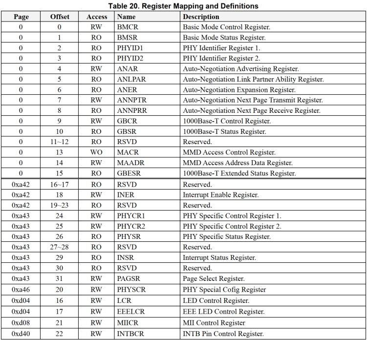
mii readcommand reads the content of a specific register at a given PHY address. Each PHY has multiple registers storing control and status data. This command helps diagnose network issues.The current board uses the RTL8221F PHY chip, whose register map is as follows:
Usage:
mii read <phy_address> <register>
<phy_address>: PHY address to read.<register>: Register number to read.
Example:
mii read 0 0x02
mii read 0 0x03
Reads registers
0x02and0x03of the PHY at address0.Sample Output:
Hobot>mii read 0 0x2
001C
Hobot>mii read 0 0x3
C916
These are the values of registers
PHYID1andPHYID2.From the RTL8221F datasheet:


Information derived:
OUI_MSB: 0x1C (high 16 bits of OUI).OUI_LSB: 110010b (low 6 bits of OUI).Model Number: 0x11.Revision Number: 0x6.
Combined OUI:
00011100b << 6 + 110010b = 011100110010b=0x732, matching the earliermii infooutput:PHY 0x00: OUI = 0x0732, Model = 0x11, Rev = 0x06, 100baseT, FDX
Additionally,
mii readsupports reading multiple registers at once:Hobot>mii read 0 0-2 addr=00 reg=00 data=1040 addr=00 reg=01 data=79AD addr=00 reg=02 data=001C
This reads registers
0x0to0x2of PHY0.mii write:
The
mii writecommand is used to write to a specific register at the specified PHY address. By modifying the values of PHY registers, users can change the configuration of network devices (such as speed, duplex mode, auto-negotiation, etc.).Usage:
mii write <phy_address> <register> <value>
<phy_address>: Specifies the PHY address to write to.<register>: Specifies the register number to write to.<value>: The value to be written into the register.
Example:
Hobot>mii read 0 0x4
01E1
Hobot>mii write 0 0x4 0x181
This command writes the value
0x181to register0x4of the PHY device at address0. After writing, themii readcommand can be used to read back the register and confirm whether the write was successful:Hobot>mii read 0 0x4 0181
mii dump:
The
mii dumpcommand prints the register contents of MII PHY devices in a human-readable format. It provides detailed information about each register’s bit fields and their meanings, effectively helping users analyze and debug the state of network devices.Usage:
mii dump <phy_address> <reg_address>
Example:
Hobot>mii dump 0 4
1.     (0181)                 -- Autonegotiation advertisement register --
  (8000:0000) 4.15    =     0     next page able
  (4000:0000) 4.14    =     0     (reserved)
  (2000:0000) 4.13    =     0     remote fault
  (1000:0000) 4.12    =     0     (reserved)
  (0800:0000) 4.11    =     0     asymmetric pause
  (0400:0000) 4.10    =     0     pause enable
  (0200:0000) 4. 9    =     0     100BASE-T4 able
  (0100:0100) 4. 8    =     1     100BASE-TX full duplex able
  (0080:0080) 4. 7    =     1     100BASE-TX able
  (0040:0000) 4. 6    =     0     10BASE-T   full duplex able
  (0020:0000) 4. 5    =     0     10BASE-T   able
  (001f:0001) 4. 4- 0 =     1     selector = IEEE 802.3 CSMA/CD
Register
0x4is the Autonegotiation Advertisement Register in the MII management interface. This register describes the speeds and modes supported by the PHY device and broadcasts these capabilities to the peer device during auto-negotiation. The value of this register is 0x0181.Field Interpretation:
0x8000(bit 15): Next Page AbleValue:
0Meaning: Does not support the Next Page extension for auto-negotiation.
0x4000(bit 14): Reserved bitValue:
0
0x2000(bit 13): Remote FaultValue:
0Meaning: No remote fault detected.
0x1000(bit 12): Reserved bitValue:
0
0x0800(bit 11): Asymmetric PauseValue:
0Meaning: Asymmetric pause mode is not supported.
0x0400(bit 10): Pause EnableValue:
0Meaning: Pause mode is not supported.
0x0200(bit 9): 100BASE-T4 AbleValue:
0Meaning: 100BASE-T4 mode is not supported.
0x0100(bit 8): 100BASE-TX Full Duplex AbleValue:
1Meaning: Supports 100Mbps full-duplex mode.
0x0080(bit 7): 100BASE-TX AbleValue:
1Meaning: Supports 100Mbps half-duplex mode.
0x0040(bit 6): 10BASE-T Full Duplex AbleValue:
0Meaning: 10Mbps full-duplex mode is not supported.
0x0020(bit 5): 10BASE-T AbleValue:
0Meaning: 10Mbps half-duplex mode is not supported.
0x001F(bits 4-0): SelectorValue:
0x0001Meaning: Selects IEEE 802.3 CSMA/CD mode.
From the output of
mii dump, the PHY device supports the following features:100BASE-TX Full Duplex: Supports 100Mbps full-duplex mode.
100BASE-TX: Supports 100Mbps half-duplex mode.
Not supported:
10BASE-T (10Mbps half-duplex mode)
10BASE-T Full Duplex (10Mbps full-duplex mode)
100BASE-T4
Pause mode
Asymmetric Pause mode
Next Page extension for auto-negotiation
Note: The PHY device by default supports 10Mbps full/half-duplex modes. However, in the
mii writeexample, the value0x181was written to register0x4, which disables these functions. Therefore, the status shown bymii dumpreflects this change.
mdio Commands
MDIO (Management Data Input/Output) is a management interface protocol defined by IEEE 802.3, used for communication between the MAC layer and PHY chips. In U-Boot, the mdio command suite is a core tool for debugging network devices, enabling read/write operations on PHY registers, device status detection, and network parameter configuration.
mdio Command Format
mdio - MDIO utility commands

Usage:
mdio list                       - List MDIO buses
mdio read <phydev> [<devad>.]<reg> - read PHY's register at <devad>.<reg>
mdio write <phydev> [<devad>.]<reg> <data> - write PHY's register at <devad>.<reg>
mdio rx <phydev> [<devad>.]<reg> - read PHY's extended register at <devad>.<reg>
mdio wx <phydev> [<devad>.]<reg> <data> - write PHY's extended register at <devad>.<reg>
mdio Parameter Explanation
<phydev>: PHY device identifier, which can take one of the following forms:<busname> <addr>: e.g.,gmac-tsn@35010000 0.<addr>: e.g.,0.<eth name>: e.g.,eth0.
<addr>: PHY device address.<devad>: Device address.<reg>: Register address.<data>: Data to be written.
mdio Command Examples
mdio list
Function: Lists all available MDIO buses and their names.
Usage:
mdio listSample Output:
Hobot>mdio list
gmac-tsn@35010000:
Output Interpretation:
gmac-tsn@35010000:
Meaning: This is an Ethernet MAC device supporting Time-Sensitive Networking (TSN).
gmac-tsn: Indicates an Ethernet MAC device with TSN support.
@35010000: Indicates the base address of the device is 0x35010000.
There is only one MDIO bus in the system, named
gmac-tsn@35010000. This means all communication with Ethernet PHY devices will go through this bus.
mdio read <phydev> [<devad>.]<reg>
Function: Reads the value of a register from the specified PHY device.
Parameters:
<phydev>: PHY device identifier, can be<busname> <addr>,<addr>, or<eth name>.<devad>: Device address (optional, default is0).<reg>: Register address.
Usage:
mdio read gmac-tsn@35010000 0 1
Sample Output:
Hobot>mdio read gmac-tsn@35010000 0 1
Reading from bus gmac-tsn@35010000
PHY at address 0:
1 - 0x79ad
Field explanations:
Reading from bus gmac-tsn@35010000: Indicates the command is executed on the MDIO bus
gmac-tsn@35010000.PHY at address 0: Indicates this is the first PHY device on the bus (address
0).1 - 0x79ad: Indicates the value
0x79adwas read from register1.
mdio write <phydev> [<devad>.]<reg> <data>
Function: Writes data to a register of the specified PHY device.
Parameters:
<phydev>: PHY device identifier.<devad>: Device address (optional, default is0).<reg>: Register address.<data>: Data to be written.
Usage:
Hobot>mdio write gmac-tsn@35010000 0 4 0x181
Field explanations:
mdio write: Used to write data to a PHY device register on the specified MDIO bus.gmac-tsn@35010000: Name of the MDIO bus, indicating the target device isgmac-tsnwith base address0x35010000.0: PHY device address, indicating the target PHY device has address0on the MDIO bus.4: Register address, indicating the register number to write is4.0x181: The data value to be written.
To verify the write operation was successful, use the
mdio readcommand to read the value of register4:Hobot>mdio read gmac-tsn@35010000 0 4 Reading from bus gmac-tsn@35010000 PHY at address 0: 4 - 0x181
As shown, the value has been successfully written.
mdio rx, mdio wx In U-Boot, the mdio rx and mdio wx commands are used to read from and write to extended registers of Ethernet PHY devices. Extended registers are typically used for advanced configuration and status information that may not be available in standard MII registers. Not all PHY devices support extended registers. Before using the mdio rx/wx commands, refer to the device datasheet to determine the correct register addresses and confirm whether the current PHY device supports access to extended registers.
Bootloader Glossary
| Term | Explanation |
|---|---|
| BootROM | Hardware-embedded initial boot code responsible for validating the first-stage bootloader |
| U-Boot | Universal Boot Loader, an open-source general-purpose bootloader widely used in embedded systems |
| SPL | Secondary Program Loader, a second-stage loader used to initialize basic hardware and load full U-Boot |
| Secure Boot | A security mechanism that ensures the integrity and trustworthiness of the boot chain through step-by-step firmware/software signature verification |
| OP-TEE | Open Portable Trusted Execution Environment, an open trusted execution environment providing secure services (e.g., key management, cryptographic operations) |
| TA | Trusted Application, a secure application running in the trusted environment |
| PTA | Pseudo Trusted Applications, interfaces exposed by the OP-TEE Core to its external world, used to protect client Trusted Applications and insecure client entities. |
| ETA | Early TA, a special type of trusted application directly linked into a dedicated data section of the TEE core blob. |
| AVB | Android Verified Boot, an Android mechanism that ensures boot chain integrity via digital signatures |
| DTS | Device Tree Source, a text-based file describing hardware configuration information |
| DTB | Device Tree Binary, a binary device tree file compiled from DTS, used by bootloaders and kernels |
| DTC | Device Tree Compiler, a tool used to compile DTS into DTB |
| FDT | Flattened Device Tree, referring to the in-memory data structure form of DTB |
| FIT | Flat Image Tree, a composite image format supported by U-Boot. Mainly used to pack multiple boot images (kernel, device tree, RAM disk, etc.) into a single file, and supports integrity verification. |