4.3.12. RTC Debug Guide
4.3.12.1. RTC Overview
The Linux RTC (Real-Time Clock) real-time clock driver subsystem is a standardized framework within the kernel for managing hardware real-time clock devices. Its core function is to maintain accurate time-base synchronization even when the system is completely powered off. The Linux kernel provides a generic RTC framework that supports various RTC chips, including those communicating via I²C, SPI, and other buses.
In the X5 chip, there is an integrated RTC module—a configurable high-precision counter with an AMBA APB interface—that provides a stable time reference for the system. Additionally, some board type of the X5 EVB , such as BOARD 1_B, includes an external PCF8563 module, which supports external battery power to maintain time continuity during system power loss.
RTC Features
Time and Date Recording
The most basic function of an RTC is to provide accurate time and date. It typically counts in seconds from a specific starting point. The RTC can provide the following time information:
Current time (hours, minutes, seconds)
Current date (year, month, day)
Day of the week
Alarm and Interrupt
Many RTC devices support setting one or more alarms. The alarm function allows users to set a specific time, and when the RTC reaches that time, it can trigger an interrupt, such as waking up the system, sending a signal, or executing a specific operation.
Periodic Wake-up
The RTC can be configured to trigger interrupts at specific time intervals. This feature is commonly used for scheduling periodic tasks, such as maintenance operations executed hourly or daily.
Time Update
The RTC allows users to update the current time, which is useful for synchronizing time at system startup or manually correcting the time. Linux provides various tools (e.g., hwclock) to set and read RTC time.
Low-Power Mode
To extend battery life, RTCs typically support low-power modes. In this mode, the RTC continues to track time while consuming minimal power.
Hardware Interface
The Linux RTC framework supports multiple hardware interfaces, including I²C, SPI, and GPIO, enabling compatibility with various RTC chips such as DS1307, DS3231, and PCF8563.
RTC Functional Principles
The RTC continuously calculates time using a precise crystal oscillator signal (typically a 32.768 kHz quartz crystal) and stores this information in internal registers in standard format (e.g., year, month, day, hour, minute, second). It relies on a backup battery to continue operating when the main power is off, ensuring time continuity, and communicates with the main control chip for time reading and setting. Its main functions include precise timekeeping, date maintenance, and alarm triggering.
Below is a brief description of the RTC working principle:
Time Counter:
The RTC internally integrates a timing circuit, typically driven by a high-precision crystal oscillator. The common oscillator frequency is 32.768 kHz, which is highly stable and suitable for long-term time measurement.
The RTC timing circuit generates a stable clock signal from the oscillator, usually a 1Hz pulse, which is then accumulated. Every second, the RTC increments its count until forming minutes, hours, dates, etc.
Date and Time Maintenance:
The RTC stores accumulated seconds, minutes, hours, dates, and other information in internal registers. These registers can be accessed and modified via communication between the system and the RTC to read or set the current time or alarm.
Some RTCs also store information such as year, month, and day of the week.
Backup Battery:
To maintain time during main system power-off, the RTC is typically equipped with a backup battery. When the main power is disconnected, the backup battery powers the RTC, ensuring its internal clock continues to operate without losing time information.
In this state, the RTC continues running, while the main controller may be in low-power or powered-off mode.
Alarm Function:
RTC modules usually have built-in alarm functionality, allowing users to set a specific time point. When the counter reaches the set time, the RTC triggers an interrupt signal or warning.
The main controller can perform corresponding actions based on this interrupt signal, such as waking up the system or starting a task.
RTC Typical Applications
RTC Time Retention
Linux system time is lost when the system shuts down, whereas the RTC can continue operating using an external battery after system shutdown, preserving the time. The system can then restore the time from the RTC upon next boot. The process is as follows:
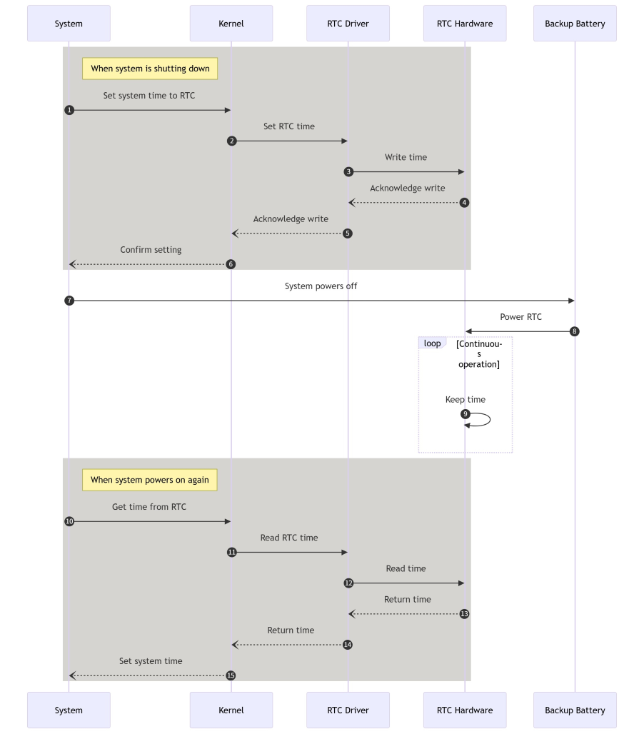
Detailed process explanation:
During System Shutdown:
Before shutdown, the system sets the current system time into the RTC.
The kernel writes the time to the RTC hardware via the RTC driver.
The RTC hardware confirms successful time write.
The RTC driver returns confirmation to the kernel.
The kernel returns confirmation to the system.
After System Shutdown:
After shutdown, the backup battery begins powering the RTC hardware.
The RTC hardware continues to run and count time under backup battery power.
On Next System Power-On:
Upon reboot, the system retrieves time from the RTC hardware via the kernel.
The kernel reads the time from the RTC hardware via the RTC driver.
The RTC hardware returns the current time to the RTC driver.
The RTC driver returns the time to the kernel.
The kernel sets the time as the system time.
RTC Periodic Wake-up
A typical application of the RTC is periodic system wake-up. The process is as follows:
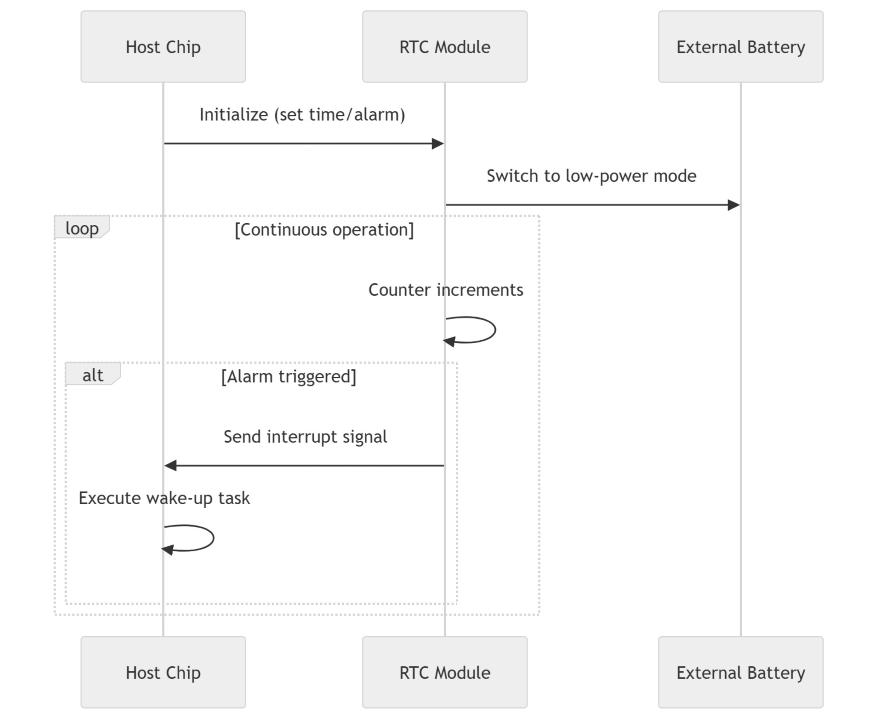
Process explanation:
Initialization Phase: The main controller first initializes communication with the RTC module, setting the current time and alarm (time reminder). This step typically occurs after system power-on, where the main controller configures time and alarm parameters via communication with the RTC module.
Switch to Low-Power Mode: After initialization, the RTC module switches to low-power mode, relying on an external battery to continuously maintain time and alarm information. The external battery provides necessary power to ensure the RTC module remains operational even when the main controller is off or in low-power state.
Continuous Operation Phase (Loop): The RTC module enters a loop mode, continuously counting (incrementing counter). This process is low-power, and the RTC module periodically updates its internal counter.
Alarm Trigger Event: At a specific time point, when the RTC module’s alarm condition is met, it sends an interrupt signal to the main controller, notifying it that the set time has been reached. Upon receiving the interrupt signal, the main controller executes predefined wake-up tasks, such as waking up the system, processing specific tasks, or performing specific functions.
4.3.12.2. RTC Driver Code
Linux RTC Driver Framework
In Linux, the RTC device driver is a standard character device driver. The Linux RTC driver framework can be abstracted into the following main components:
User Space: At the top layer, includes user tools and interfaces to kernel space.
Kernel Space: In the middle layer, divided into three parts:
Interface Layer: Directly interacts with user space.
RTC Core: Core module managing RTC devices.
RTC Driver Layer: Directly interacts with the hardware layer.
Hardware Layer: At the bottom layer, representing the actual RTC hardware devices.
The Linux RTC driver framework is illustrated in the figure below:
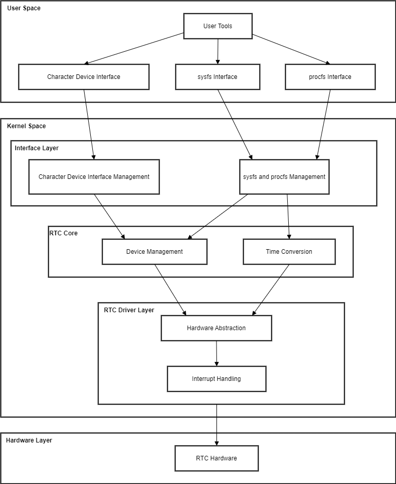
Each layer is described below.
RTC User Space (User Space):
User space interacts with RTC devices primarily through the following methods:
User Tools:
hwclock: Hardware clock operation tool.date: System time operation tool.Test tools: e.g.,
rtctest.c, used to test the RTC driver’sioctlinterface.
Character Device Interface:
/dev/rtcN: Character device node supportingopen,read,write, andioctloperations.
sysfs Interface:
/sys/class/rtc/rtcN: Provides read-only attributes such as time and alarm, allowing user space to access certain RTC device properties.
procfs Interface:
/proc/driver/rtc: Provides information about the system clock RTC. If the system lacks a dedicated RTC, it defaults to usingrtc0.
RTC Kernel Space (Kernel Space):
The various modules in kernel space are responsible for RTC driver management, device registration, and interaction with user space:
Interface Layer (Interface Layer):
Manages character device interface.
Manages sysfs and procfs attributes.
RTC Core (Core Layer):
Device Management:
Device Registration and Unregistration: Uses
registerandunregisterfunctions to register and unregister RTC devices.Character Device Abstraction: Uses
dev.cto abstract RTC devices as generic character devices, providing file operation functions.sysfs and procfs Management: Uses
sysfs.candproc.cto manage RTC device sysfs and procfs attributes.
Time Conversion: Uses
lib.cto provide conversion between RTC time and system time.
RTC Driver Layer (Driver Layer):
Hardware Abstraction:
Operation Function Set: Defined via the
rtc_class_opsstructure, provides low-level operations on RTC hardware, such as reading/writing time, reading/setting alarms, etc.Hardware Initialization: Initializes RTC hardware, configures clock sources, interrupts, etc.
Interrupt Handling: Handles interrupts generated by the RTC, such as alarm and periodic interrupts.
Data Structures:
struct rtc_device: Describes the RTC device.struct rtc_class_ops: Defines low-level operation functions.
RTC Hardware Layer (Hardware Layer):
RTC Hardware:
Hardware clock chip (e.g., PCF8563)
Crystal oscillator
External battery
RTC Driver Code Explanation
This section explains the following three main parts of the RTC subsystem code:
rtc driver Layer: Registers the RTC device into the RTC subsystem and provides a set of low-level operation functions for the RTC device.
rtc core: Responsible for RTC device registration and unregistration, provides RTC character device files to user space, and implements sysfs and other interfaces for the RTC class.
User Space Interface: Includes interfaces such as
ioctl.
RTC Driver Layer Code Explanation
The RTC driver layer code is primarily responsible for directly operating the RTC module. In Linux systems, the kernel abstracts the RTC device as the rtc_device structure. The main task of the RTC driver layer is to allocate and initialize rtc_device.
RTC device abstraction in the Linux kernel is as follows:
// kernel/include/linux/rtc.h
struct rtc_device {
	struct device dev;
	struct module *owner;

	int id;

	const struct rtc_class_ops *ops;
	struct mutex ops_lock;

	struct cdev char_dev;
	unsigned long flags;

	unsigned long irq_data;
	spinlock_t irq_lock;
	wait_queue_head_t irq_queue;
	struct fasync_struct *async_queue;

	int irq_freq;
	int max_user_freq;

	struct timerqueue_head timerqueue;
	struct rtc_timer aie_timer;
	struct rtc_timer uie_rtctimer;
	struct hrtimer pie_timer; /* sub second exp, so needs hrtimer */
	int pie_enabled;
	struct work_struct irqwork;

	/*
	 * This offset specifies the update timing of the RTC.
	 *
	 * tsched     t1 write(t2.tv_sec - 1sec))  t2 RTC increments seconds
	 *
	 * The offset defines how tsched is computed so that the write to
	 * the RTC (t2.tv_sec - 1sec) is correct versus the time required
	 * for the transport of the write and the time which the RTC needs
	 * to increment seconds the first time after the write (t2).
	 *
	 * For direct accessible RTCs tsched ~= t1 because the write time
	 * is negligible. For RTCs behind slow busses the transport time is
	 * significant and has to be taken into account.
	 *
	 * The time between the write (t1) and the first increment after
	 * the write (t2) is RTC specific. For a MC146818 RTC it's 500ms,
	 * for many others it's exactly 1 second. Consult the datasheet.
	 *
	 * The value of this offset is also used to calculate the to be
	 * written value (t2.tv_sec - 1sec) at tsched.
	 *
	 * The default value for this is NSEC_PER_SEC + 10 msec default
	 * transport time. The offset can be adjusted by drivers so the
	 * calculation for the to be written value at tsched becomes
	 * correct:
	 *
	 *	newval = tsched + set_offset_nsec - NSEC_PER_SEC
	 * and  (tsched + set_offset_nsec) % NSEC_PER_SEC == 0
	 */
	unsigned long set_offset_nsec;

	unsigned long features[BITS_TO_LONGS(RTC_FEATURE_CNT)];

	time64_t range_min;
	timeu64_t range_max;
	time64_t start_secs;
	time64_t offset_secs;
	bool set_start_time;

#ifdef CONFIG_RTC_INTF_DEV_UIE_EMUL
	struct work_struct uie_task;
	struct timer_list uie_timer;
	/* Those fields are protected by rtc->irq_lock */
	unsigned int oldsecs;
	unsigned int uie_irq_active:1;
	unsigned int stop_uie_polling:1;
	unsigned int uie_task_active:1;
	unsigned int uie_timer_active:1;
#endif
};
The RTC hardware layer driver relies on a series of ops functions to operate the RTC module. The kernel has already provided a unified interface for these functions. These interfaces are defined in the struct rtc_class_ops *ops member of the rtc_device structure mentioned above. rtc_class_ops is the lowest-level operation function set for the RTC device, including operations such as reading and setting RTC device time:
// kernel/include/linux/rtc.h
/*
 * For these RTC methods the device parameter is the physical device
 * on whatever bus holds the hardware (I2C, Platform, SPI, etc), which
 * was passed to rtc_device_register().  Its driver_data normally holds
 * device state, including the rtc_device pointer for the RTC.
 *
 * Most of these methods are called with rtc_device.ops_lock held,
 * through the rtc_*(struct rtc_device *, ...) calls.
 *
 * The (current) exceptions are mostly filesystem hooks:
 *   - the proc() hook for procfs
 */
struct rtc_class_ops {
	int (*ioctl)(struct device *, unsigned int, unsigned long);
	int (*read_time)(struct device *, struct rtc_time *);
	int (*set_time)(struct device *, struct rtc_time *);
	int (*read_alarm)(struct device *, struct rtc_wkalrm *);
	int (*set_alarm)(struct device *, struct rtc_wkalrm *);
	int (*proc)(struct device *, struct seq_file *);
	int (*alarm_irq_enable)(struct device *, unsigned int enabled);
	int (*read_offset)(struct device *, long *offset);
	int (*set_offset)(struct device *, long offset);
	int (*param_get)(struct device *, struct rtc_param *param);
	int (*param_set)(struct device *, struct rtc_param *param);
};
From the function names, we can clearly understand the function of each function, such as reading/writing time, reading/setting alarms, enabling alarm interrupts, etc. The specific implementation of the rtc_class_ops operation set needs to be tailored to the RTC device being used.
Take the PCF8563 driver in the BSP source code as an example:
// kernel/drivers/rtc/rtc-pcf8563.c
static const struct rtc_class_ops pcf8563_rtc_ops = {
	.ioctl		= pcf8563_rtc_ioctl,
	.read_time	= pcf8563_rtc_read_time,
	.set_time	= pcf8563_rtc_set_time,
	.read_alarm	= pcf8563_rtc_read_alarm,
	.set_alarm	= pcf8563_rtc_set_alarm,
	.alarm_irq_enable = pcf8563_irq_enable,
};
These operation functions are implemented in the PCF8563 driver according to the specific hardware interface, generally involving direct register manipulation based on actual hardware, and are provided to the RTC subsystem via the rtc_class_ops structure pointer. Through these functions, the kernel can control the PCF8563 module.
Note: The functions in rtc_class_ops are only low-level operations on the RTC device, not the file_operations set provided to the application layer. The Linux kernel provides a generic RTC character device driver file drivers/rtc/rtc-dev.c, which implements the shared file_operations set for all RTC devices.
The rtc_init function implements the initialization of the RTC subsystem. The relevant source code is as follows:
// kernel/drivers/rtc/class.c
static int __init rtc_init(void)
{
    rtc_class = class_create(THIS_MODULE, "rtc");
    if (IS_ERR(rtc_class)) {
        pr_err("couldn't create class\n");
        return PTR_ERR(rtc_class);
    }
    rtc_class->pm = RTC_CLASS_DEV_PM_OPS;
    rtc_dev_init();
    return 0;
}
subsys_initcall(rtc_init);
During the RTC subsystem initialization, the main tasks include allocating the rtc_class class and initializing the RTC device’s rtc_devt. The alloc_chrdev_region function is used to dynamically allocate device numbers. The call sequence is as follows:
rtc_init
  ---> class_create(THIS_MODULE, "rtc")         // Create rtc_class class.
    ---> rtc_dev_init()
      ---> alloc_chrdev_region(&rtc_devt, 0, RTC_DEV_MAX, "rtc")    // Allocate sub-device numbers 0~15 for rtc devices, major number assigned randomly, final result stored in rtc_devt.
RTC Core Code Explanation
The RTC core layer in the Linux kernel is responsible for managing and scheduling RTC-related device resources and providing a unified interface for RTC devices.
After the RTC driver layer prepares the rtc_class_ops structure, it can register the RTC resource with the Linux kernel through the interface devm_rtc_device_register in the RTC core layer.
Relevant source code:
//kernel/drivers/rtc/class.c
/**
 * devm_rtc_device_register - resource managed rtc_device_register()
 * @dev: the device to register
 * @name: the name of the device (unused)
 * @ops: the rtc operations structure
 * @owner: the module owner
 *
 * @return a struct rtc on success, or an ERR_PTR on error
 *
 * Managed rtc_device_register(). The rtc_device returned from this function
 * are automatically freed on driver detach.
 * This function is deprecated, use devm_rtc_allocate_device and
 * rtc_register_device instead
 */
struct rtc_device *devm_rtc_device_register(struct device *dev,
					    const char *name,
					    const struct rtc_class_ops *ops,
					    struct module *owner)
{
	struct rtc_device *rtc;
	int err;

	rtc = devm_rtc_allocate_device(dev);
	if (IS_ERR(rtc))
		return rtc;

	rtc->ops = ops;

	err = __devm_rtc_register_device(owner, rtc);
	if (err)
		return ERR_PTR(err);

	return rtc;
}
EXPORT_SYMBOL_GPL(devm_rtc_device_register);
Here, rtc->ops = ops sets the rtc_class_ops low-level operation set.
Next, we mainly analyze __devm_rtc_register_device, a function used to register the RTC device into the system:
//kernel/drivers/rtc/class.c
int __devm_rtc_register_device(struct module *owner, struct rtc_device *rtc)
{
	struct rtc_wkalrm alrm;
	int err;

	if (!rtc->ops) {
		dev_dbg(&rtc->dev, "no ops set\n");
		return -EINVAL;
	}

	if (!rtc->ops->set_alarm)
		clear_bit(RTC_FEATURE_ALARM, rtc->features);

	if (rtc->ops->set_offset)
		set_bit(RTC_FEATURE_CORRECTION, rtc->features);

	rtc->owner = owner;
	rtc_device_get_offset(rtc);

	/* Check to see if there is an ALARM already set in hw */
	err = __rtc_read_alarm(rtc, &alrm);
	if (!err && !rtc_valid_tm(&alrm.time))
		rtc_initialize_alarm(rtc, &alrm);

	rtc_dev_prepare(rtc);

	err = cdev_device_add(&rtc->char_dev, &rtc->dev);  // Add RTC device as character device
	if (err) {
		set_bit(RTC_NO_CDEV, &rtc->flags);
		dev_warn(rtc->dev.parent, "failed to add char device %d:%d\n",
			 MAJOR(rtc->dev.devt), rtc->id);
	} else {
		dev_dbg(rtc->dev.parent, "char device (%d:%d)\n",
			MAJOR(rtc->dev.devt), rtc->id);
	}

	rtc_proc_add_device(rtc);  // Add RTC device to proc filesystem

	dev_info(rtc->dev.parent, "registered as %s\n",
		 dev_name(&rtc->dev));

#ifdef CONFIG_RTC_HCTOSYS_DEVICE
	if (!strcmp(dev_name(&rtc->dev), CONFIG_RTC_HCTOSYS_DEVICE))
		rtc_hctosys(rtc);
#endif

	return devm_add_action_or_reset(rtc->dev.parent,
					devm_rtc_unregister_device, rtc);
}
EXPORT_SYMBOL_GPL(__devm_rtc_register_device);
It calls the rtc_dev_prepare function to prepare RTC device resources. Relevant code is as follows:
// kernel/drivers/rtc/dev.c
void rtc_dev_prepare(struct rtc_device *rtc)
{
  if (!rtc_devt)
    return;

  if (rtc->id >= RTC_DEV_MAX) {
    dev_dbg(&rtc->dev, "too many RTC devices\n");
    return;
  }

  rtc->dev.devt = MKDEV(MAJOR(rtc_devt), rtc->id);

#ifdef CONFIG_RTC_INTF_DEV_UIE_EMUL
  INIT_WORK(&rtc->uie_task, rtc_uie_task);
  timer_setup(&rtc->uie_timer, rtc_uie_timer, 0);
#endif

  cdev_init(&rtc->char_dev, &rtc_dev_fops);
  rtc->char_dev.owner = rtc->owner;
}
The main purpose of the rtc_dev_prepare function is to prepare the data structures and resources required by the RTC device in the kernel so that the device can be recognized by the system and correctly communicate with user space. It acts as a bridge in the Linux kernel’s RTC driver framework, connecting the RTC hardware driver layer with the user space layer. This process includes the following key steps:
Initialize Device Number:
Assign a unique device number (
devt) to the RTC device, which is an identifier used by the kernel to recognize the device. The device number consists of a major and minor number, where the major number usually identifies the device type, and the minor number distinguishes multiple instances of the same device type.
Initialize Character Device Structure:
Initialize the character device structure (
cdev) of the RTC device, which contains file operation functions (file_operations) that define how user space programs interact with the device file. For example, when a user space program opens, reads, writes, or performs I/O control operations (ioctl), the kernel calls these functions.
Set File Operations:
Associate
rtc_dev_fops(afile_operationsstructure) with the RTC device’s character device structure. This way, when a user space program operates on the device file, the kernel calls these predefined functions to perform the corresponding hardware operations.
Register Device:
Call the
cdev_device_addfunction to add the RTC device’s character device to the system, enabling user space programs to access the RTC device via device files such as/dev/rtcN.
Initialize Other Features:
Initialize other functions as needed, such as timers, typically used to handle specific RTC functionalities.
User Space Interface Code Explanation
procfs Interface Function:
Call the
rtc_proc_add_devicefunction to add the RTC device to the proc filesystem.// kernel/drivers/rtc/proc.c void rtc_proc_add_device(struct rtc_device *rtc) { if (is_rtc_hctosys(rtc)) proc_create_single_data("driver/rtc", 0, NULL, rtc_proc_show, rtc); }
The main purpose of the rtc_proc_add_device function is to expose RTC device information to user space by providing an interface through the /proc file system, allowing user-space programs to conveniently read the status and configuration of the RTC device. This enables user-space applications to obtain device information from the kernel in a standardized way, without directly accessing internal data structures of the device driver.
Upon successful execution of the rtc_proc_add_device function, a file named driver/rtc is created under the /proc directory. This file is associated with the RTC device and typically contains the following content:
root@buildroot:~# cat /proc/driver/rtc
rtc_time        : 00:01:00
rtc_date        : 1970-01-01
alrm_time       : 00:00:00
alrm_date       : 1970-01-01
alarm_IRQ       : no
alrm_pending    : no
update IRQ enabled      : no
periodic IRQ enabled    : no
periodic IRQ frequency  : 1
max user IRQ frequency  : 64
24hr            : yes
The /proc/driver/rtc file provides detailed information about the state of the RTC device. The meaning of each field is explained below:
View RTC Time
The
rtc_timeandrtc_datefields represent the current hour, minute, second, year, month, and day of the RTC device. This is useful for verifying whether the RTC device is functioning correctly.
Check Alarm Settings
alrm_timeandalrm_datedisplay the alarm settings of the RTC device. If these values are not as expected, the alarm may need to be reconfigured.alarm_IRQindicates whether an interrupt request (IRQ) is associated with the alarm. A value ofyesmeans the RTC device supports alarm interrupts.alrm_pendingindicates whether there is a pending alarm event.
Monitor Interrupt Status
update IRQ enabledandperiodic IRQ enabledshow whether update interrupts and periodic interrupts are enabled on the RTC device. These interrupts can be used for timing tasks or event triggering.periodic IRQ frequencyandmax user IRQ frequencyprovide information about the frequency of periodic interrupts, which is crucial for applications requiring precise timing.
Time Format
24hrindicates whether the RTC device uses 24-hour format. This is important for applications that need to convert between 12-hour and 24-hour formats.
Common use cases for the /proc/driver/rtc file include:
System Monitoring: Users can use this file to monitor the status of the RTC device, ensuring time synchronization and alarm functionality work properly.
Troubleshooting: If the RTC device has issues such as inaccurate time or failed alarm triggering, this file can provide clues for diagnosis.
Configuration Verification: After configuring the RTC device, users can check this file to verify that the configuration has been applied correctly.
Application Development: Developers creating applications that interact with the RTC device can refer to this file to obtain device status and capability information.
ioctl Interface Functions:
The
cdev_initfunction is called to initialize the character device structure (rtc->char_dev) of the RTC device and set its file operation pointer tortc_dev_fops. This is a structure containing file operation functions for the RTC device. When user-space programs open, read, write, or perform other operations on the associated device file, the kernel invokes these functions.
// kernel/drivers/rtc/dev.c
static const struct file_operations rtc_dev_fops = {
  .owner		= THIS_MODULE,
  .llseek		= no_llseek,
  .read		= rtc_dev_read,
  .poll		= rtc_dev_poll,
  .unlocked_ioctl	= rtc_dev_ioctl,
#ifdef CONFIG_COMPAT
  .compat_ioctl	= rtc_dev_compat_ioctl,
#endif
  .open		= rtc_dev_open,
  .release	= rtc_dev_release,
  .fasync		= rtc_dev_fasync,
};
The rtc_dev_fops structure is used in user space. In the Linux kernel, struct file_operations (usually referenced via a pointer fops) defines a series of file operation functions that implement operations on device files. When user-space programs call system calls such as ioctl, read, or write on a device-associated file, the kernel invokes the corresponding functions.
The rtc_dev_fops structure defines a set of file operations for interacting with the RTC device, including:
.owner: Specifies which module owns these operations. It is usually set toTHIS_MODULE, indicating the current module..llseek: File positioning operation;no_llseekindicates the device does not support standard file seeking..read: Function to read data from the RTC device, invoked when a user-space program calls theread()system call..poll: Polling function used for non-blocking I/O operations, such as whenselect()orpoll()system calls are used..unlocked_ioctl: Function to perform device-specific operations, such as getting or setting RTC time. This function is used by theioctl()system call..compat_ioctl:ioctlfunction for compatibility mode, supporting 32-bit programs running on 64-bit systems..open: Function called when opening the RTC device file..release: Function called when closing the RTC device file..fasync: Function used for asynchronous I/O notifications.
These operation functions are invoked by the kernel when user-space programs interact with the RTC device through the file system. For example, when a user program opens the /dev/rtcN device file, the kernel calls the rtc_dev_open function; when reading from the file, it calls rtc_dev_read.
It is important to note the rtc_dev_ioctl function, which is the core function in the RTC driver for handling I/O control operations. It is primarily responsible for executing corresponding RTC operations based on the incoming command and parameters:
kernel/drivers/rtc/dev.c
static long rtc_dev_ioctl(struct file *file,
        unsigned int cmd, unsigned long arg)
{
  int err = 0;
  struct rtc_device *rtc = file->private_data;
  const struct rtc_class_ops *ops = rtc->ops;
  struct rtc_time tm;
  struct rtc_wkalrm alarm;
  struct rtc_param param;
  void __user *uarg = (void __user *)arg;

  err = mutex_lock_interruptible(&rtc->ops_lock);
  if (err)
    return err;

  /* check that the calling task has appropriate permissions
  * for certain ioctls. doing this check here is useful
  * to avoid duplicate code in each driver.
  */
  switch (cmd) {
  case RTC_EPOCH_SET:
  case RTC_SET_TIME:
  case RTC_PARAM_SET:
    if (!capable(CAP_SYS_TIME))
      err = -EACCES;
    break;

  case RTC_IRQP_SET:
    if (arg > rtc->max_user_freq && !capable(CAP_SYS_RESOURCE))
      err = -EACCES;
    break;

  case RTC_PIE_ON:
    if (rtc->irq_freq > rtc->max_user_freq &&
        !capable(CAP_SYS_RESOURCE))
      err = -EACCES;
    break;
  }
  ……
}
When applications use the ioctl function to perform operations such as setting/reading time or configuring alarms, the rtc_dev_ioctl function is invoked. Ultimately, rtc_dev_ioctl calls functions like read_time, set_time, etc., from the lower-level operation set rtc_class_ops to perform actual read/write operations on the specific RTC hardware.
Linking the above code together, the sequence diagram for interaction between user-space programs and the RTC device is as follows:
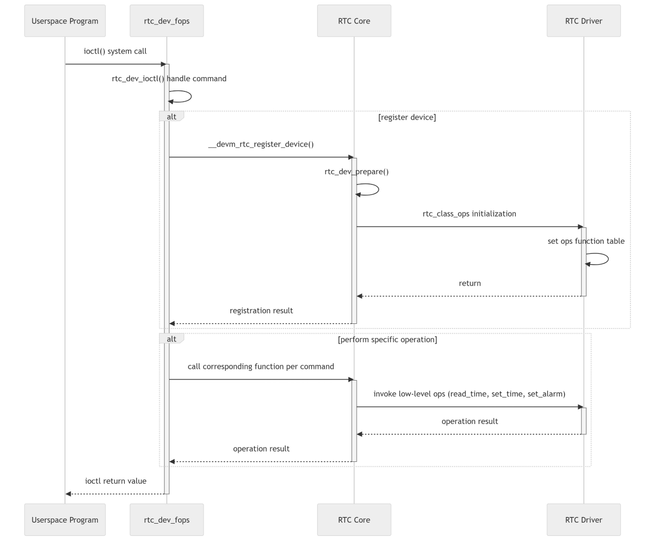
Detailed explanation:
User-Space Program:
Initiates an
ioctl()system call to request an operation on the RTC device.
RTC User Interface (
rtc_dev_fops):Upon receiving the
ioctl()call, invokes thertc_dev_ioctl()function to handle the specific command.The RTC user interface acts as a bridge between user space and the kernel.
RTC Core:
If the RTC device is used for the first time, calls
__devm_rtc_register_device()to register the device.Calls
rtc_dev_prepare()to prepare device resources.Initializes
rtc_class_opsand sets up the lower-level operation function set.Based on the command from the user-space program, calls the corresponding lower-level operation functions (e.g.,
read_time,set_time,set_alarm, etc.).
RTC Driver:
Provides the lower-level operation function set (
rtc_class_ops) and directly interacts with the RTC hardware.Performs specific hardware operations and returns results to the RTC core.
Return Results:
Operation results are returned layer by layer back to the user-space program, which continues execution based on the returned result.
4.3.12.3. Kernel Configuration
Enter the Linux kernel configuration interface using the command ./bd.sh boot menuconfig. In the menuconfig interface, navigate to the RTC configuration options via the following path:
Device Drivers  --->
     Real Time Clock  --->
Then select the required configuration items as needed. Typical configurations are as follows:
CONFIG_RTC_LIB=y
CONFIG_RTC_CLASS=y
CONFIG_RTC_HCTOSYS=y
CONFIG_RTC_HCTOSYS_DEVICE="rtc0"
CONFIG_RTC_SYSTOHC=y
CONFIG_RTC_SYSTOHC_DEVICE="rtc0"
CONFIG_RTC_DEBUG=y
CONFIG_RTC_NVMEM=y

CONFIG_RTC_INTF_SYSFS=y
CONFIG_RTC_INTF_PROC=y
CONFIG_RTC_INTF_DEV=y
Explanations of these configuration options are as follows:
Core Configuration Options:
CONFIG_RTC_LIB=yEnables RTC library support. This option enables the basic RTC operation function library for use by other modules or drivers.
CONFIG_RTC_CLASS=yEnables the RTC class. This creates an RTC subsystem, allowing the kernel to manage multiple RTC devices and provide relevant interfaces to users.
CONFIG_RTC_HCTOSYS=yEnables the system to set time from the RTC. During boot, the kernel reads the time from the specified RTC device (defined by
CONFIG_RTC_HCTOSYS_DEVICE) and uses it as the system time.
CONFIG_RTC_HCTOSYS_DEVICE="rtc0"Specifies which RTC device to read time from. This option tells the kernel to use the time from
rtc0at boot.
CONFIG_RTC_SYSTOHC=yEnables writing the system time back to the RTC. This causes the kernel to save the current system time back to the specified RTC device.
CONFIG_RTC_SYSTOHC_DEVICE="rtc0"Specifies which RTC device is used to store the system time. This option sets the system time to be written back to
rtc0.
CONFIG_RTC_DEBUG=yEnables RTC debug message output. When enabled, additional debug information is printed, aiding in debugging RTC-related issues.
CONFIG_RTC_NVMEM=yEnables non-volatile memory support for RTC. This allows the RTC to provide a non-volatile storage area for configuration data.
RTC Interface-Related Configuration Options:
CONFIG_RTC_INTF_SYSFS=yEnables the RTC sysfs interface. This creates RTC device information under
/sys/class/rtc/, allowing user interaction via the sysfs interface.
CONFIG_RTC_INTF_PROC=yEnables the RTC proc interface. The kernel creates the
/proc/rtcfile, allowing interaction with the RTC device through the proc file system.
CONFIG_RTC_INTF_DEV=yEnables the RTC character device interface. This allows RTC devices to appear as
/dev/rtcN, enabling user-space applications (likehwclock) to perform read/write operations.
Additionally, the X5 chip has an internal RTC module (/dev/rtc0), and the X5 EVB currently has an external PCF8563 (/dev/rtc1), so the following options are enabled:
CONFIG_RTC_DRV_DWAPB=y     # /dev/rtc0
CONFIG_RTC_DRV_PCF8563=m   # /dev/rtc1
Explanations of these two options:
CONFIG_RTC_DRV_DWAPB=yEnables the DWAPB driver, which supports the internal RTC module of the X5 chip. This option allows the kernel to recognize and drive the
/dev/rtc0device, enabling the internal RTC to serve as a system time source.
CONFIG_RTC_DRV_PCF8563=mEnables the PCF8563 RTC driver as a loadable module (
mdenotes module). This driver supports the external PCF8563 RTC chip (connected via I2C on the X5 EVB). Loading this module allows the external PCF8563 RTC to be recognized and used as/dev/rtc1.
4.3.12.4. RTC Usage Overview
RTC Testing Methods
After the driver is successfully loaded, /dev/rtcN device nodes will appear:
root@buildroot:~# ls /dev/rtc*
/dev/rtc  /dev/rtc0  /dev/rtc1
The system currently has two RTC devices: /dev/rtc0 and /dev/rtc1, corresponding to the internal RTC module rtc-dwapb and the external RTC PCF8563, respectively. The exact mapping can be determined from the kernel boot log:
root@buildroot:~# dmesg | grep rtc
[    0.577125] dw-rtc 31010000.rtc: prescaler set to: 24000000
[    0.577462] dw-rtc 31010000.rtc: char device (253:0)
[    0.577474] dw-rtc 31010000.rtc: registered as rtc0
[    0.577491] dw-rtc 31010000.rtc: setting system clock to 1970-01-01T00:00:00 UTC (0)
[    1.306790] rtc-pcf8563 4-0051: pcf8563_probe
[    1.308632] rtc-pcf8563 4-0051: low voltage detected, date/time is not reliable.
[    1.309614] rtc rtc1: read_time: fail to read: -22
[    1.309838] rtc-pcf8563 4-0051: char device (253:1)
[    1.309854] rtc-pcf8563 4-0051: registered as rtc1
Thus, /dev/rtc0 corresponds to the internal rtc-dwapb, and /dev/rtc1 to the external RTC PCF8563.
By default, the system uses /dev/rtc0 as the primary RTC device /dev/rtc:
root@buildroot:~# ls -l  /dev/rtc
lrwxrwxrwx 1 root root 4 Jan  1 00:00 /dev/rtc -> rtc0
This refers to the internal rtc-dwapb. You can test it using the following commands:
# Test commands
date -s "2024/01/01 17:00:00"				# Set system time
hwclock -w						# Write system time to RTC
hwclock -r						# Read RTC time to confirm successful write
date							# Read system time
You can now verify the configuration results via the /proc interface:
root@buildroot:~# cat /proc/driver/rtc
rtc_time        : 00:15:09
rtc_date        : 1970-01-01
alrm_time       : 00:00:00
alrm_date       : 1970-01-01
alarm_IRQ       : no
alrm_pending    : no
update IRQ enabled      : no
periodic IRQ enabled    : no
periodic IRQ frequency  : 1
max user IRQ frequency  : 64
24hr            : yes
root@buildroot:~# date -s "2024/01/01 17:00:00"
Mon Jan  1 17:00:00 UTC 2024
root@buildroot:~# hwclock -w
root@buildroot:~# hwclock -r
Mon Jan  1 17:00:11 2024  0.000000 seconds
root@buildroot:~# date
Mon Jan  1 17:00:14 UTC 2024
root@buildroot:~# cat /proc/driver/rtc
rtc_time        : 17:00:20
rtc_date        : 2024-01-01
alrm_time       : 00:00:00
alrm_date       : 1970-01-01
alarm_IRQ       : no
alrm_pending    : no
update IRQ enabled      : no
periodic IRQ enabled    : no
periodic IRQ frequency  : 1
max user IRQ frequency  : 64
24hr            : yes
As shown, rtc_time has been successfully configured.
For basic testing of the external RTC module PCF8563, refer to the RTC Interface section.
RTC Test Interfaces
Below are common interface functions for RTC in user-space applications. These functions provide a basic framework for interacting with RTC devices. Users can adjust and enhance them based on specific hardware and requirements.
set_rtc_time Function
Function: Sets the RTC time.
Parameters:
int fd, file descriptor;struct rtc_time rtc_tm, contains the time to be set.Implementation: Uses the
ioctlsystem call with theRTC_SET_TIMEcommand to write the time to the RTC.Error Handling: If the
ioctlcall fails, outputs an error message and closes the file descriptor.Code Example:
int set_rtc_time(int fd, struct rtc_time rtc_tm)
{
    int ret;
    ret = ioctl(fd, RTC_SET_TIME, &rtc_tm);
    if (ret < 0) {
        printf("<%s %d> ERR: set rtc time failed!\n", __func__, __LINE__);
        close(fd);
        return -1;
    }
    return 0;
}
read_rtc_time Function
Function: Reads the current RTC time.
Parameters:
int fd, file descriptor;struct rtc_time *rtc_tm, stores the read time.Implementation: Uses the
ioctlsystem call with theRTC_RD_TIMEcommand to read the RTC time and callsprint_rtc_timeto output it.Error Handling: If the
ioctlcall fails, outputs an error message and closes the file descriptor.Code Example:
int read_rtc_time(int fd, struct rtc_time *rtc_tm)
{
    int ret;
    ret = ioctl(fd, RTC_RD_TIME, rtc_tm);
    if (ret < 0) {
        printf("<%s %d> ERR: read rtc time failed!\n", __func__, __LINE__);
        close(fd);
        return -1;
    }
    print_rtc_time(rtc_tm);
    return 0;
}
alm_set_rtc Function
Function: Sets the RTC alarm time.
Parameters:
int fd, file descriptor;struct rtc_time rtc_tm, the alarm time to be set.Implementation: Uses the
ioctlsystem call with theRTC_ALM_SETcommand to set the alarm time.Error Handling: If the
ioctlcall fails, outputs an error message and closes the file descriptor.Code Example:
int alm_set_rtc(int fd, struct rtc_time rtc_tm)
{
    int ret;
    ret = ioctl(fd, RTC_ALM_SET, &rtc_tm);
    if (ret < 0) {
        printf("<%s %d> ERR: set alarm failed!\n", __func__, __LINE__);
        close(fd);
        return -1;
    }
    return 0;
}
alm_read_rtc Function
Function: Reads the RTC alarm time.
Parameters:
int fd, file descriptor;struct rtc_time *rtc_tm, stores the read alarm time.Implementation: Uses the
ioctlsystem call with theRTC_ALM_READcommand to read the alarm time and callsprint_rtc_timeto output it.Error Handling: If the
ioctlcall fails, outputs an error message and closes the file descriptor.Code Example:
int alm_read_rtc(int fd, struct rtc_time *rtc_tm)
{
    int ret;
    ret = ioctl(fd, RTC_ALM_READ, rtc_tm);
    if (ret < 0) {
        printf("<%s %d> ERR: read alarm failed!\n", __func__, __LINE__);
        close(fd);
        return -1;
    }
    print_rtc_time(rtc_tm);
    return 0;
}
alm_rtc_enable Function
Function: Enables RTC alarm interrupt.
Parameters:
int fd, file descriptor.Implementation: Uses the
ioctlsystem call with theRTC_AIE_ONcommand to enable the alarm interrupt.Error Handling: If the
ioctlcall fails, outputs an error message and closes the file descriptor.Code Example:
int alm_rtc_enable(int fd)
{
    int ret;
    ret = ioctl(fd, RTC_AIE_ON, 0);
    if (ret < 0) {
        printf("<%s %d> ERR: enable alarm failed!\n", __func__, __LINE__);
        close(fd);
        return -1;
    }
    return 0;
}
alm_rtc_disable Function
Function: Disables RTC alarm interrupt.
Parameters:
int fd, file descriptor.Implementation: Uses the
ioctlsystem call with theRTC_AIE_OFFcommand to disable the alarm interrupt.Error Handling: If the
ioctlcall fails, outputs an error message and closes the file descriptor.Code Example:
int alm_rtc_disable(int fd)
{
    int ret;
    ret = ioctl(fd, RTC_AIE_OFF, 0);
    if (ret < 0) {
        printf("<%s %d> ERR: disable alarm failed!\n", __func__, __LINE__);
        close(fd);
        return -1;
    }
    return 0;
}
The IOCTL commands used in the above interface functions (RTC_SET_TIME, RTC_RD_TIME, RTC_AIE_OFF, etc.) are predefined in the previously mentioned driver code section, specifically in the rtc_dev_ioctl function.
RTC Test Case
Below is a simple RTC test case.
#include <stdio.h>
#include <fcntl.h>
#include <unistd.h>
#include <sys/ioctl.h>
#include <errno.h>
#include <time.h>
#include <linux/rtc.h>

#define RTC_DEVICE "/dev/rtc0"

int set_rtc_time(int fd, struct rtc_time rtc_tm)
{
    int ret;

    ret = ioctl(fd, RTC_SET_TIME, &rtc_tm);
    if (ret < 0) {
        printf("<%s %d> ERR: set rtc time failed!\n", __func__, __LINE__);
        close(fd);
        return -1;
    }

    return 0;
}

int read_rtc_time(int fd, struct rtc_time *rtc_tm)
{
    int ret;

    ret = ioctl(fd, RTC_RD_TIME, rtc_tm);
    if (ret < 0) {
        printf("<%s %d> ERR: read rtc time failed!\n", __func__, __LINE__);
        close(fd);
        return -1;
    }

    return 0;
}

int alm_set_rtc(int fd, struct rtc_time rtc_tm)
{
    int ret;

    ret = ioctl(fd, RTC_ALM_SET, &rtc_tm);
    if (ret < 0) {
        printf("<%s %d> ERR: set alarm failed!\n", __func__, __LINE__);
        close(fd);
        return -1;
    }

    return 0;
}

int alm_read_rtc(int fd, struct rtc_time *rtc_tm)
{
    int ret;

    ret = ioctl(fd, RTC_ALM_READ, rtc_tm);
    if (ret < 0) {
        printf("<%s %d> ERR: read alarm failed!\n", __func__, __LINE__);
        close(fd);
        return -1;
    }

    return (0);
}

int alm_rtc_enable(int fd)
{
    int ret;

    ret = ioctl(fd, RTC_AIE_ON, 0);
    if (ret < 0) {
        printf("<%s %d> ERR: enable alarm failed!\n", __func__, __LINE__);

        close(fd);
        return -1;
    }

    return 0;
}

int alm_rtc_disable(int fd)
{
    int ret;

    ret = ioctl(fd, RTC_AIE_OFF, 0);
    if (ret < 0) {
        printf("<%s %d> ERR: disable alarm failed!\n", __func__, __LINE__);

        close(fd);
        return -1;
    }

    return (0);
}

int main() {
    int fd;
    struct rtc_time rtc_tm;
    struct rtc_wkalrm alarm_tm;
    int ret;
    int choice;

    // Open RTC device file, typically "/dev/rtc0"
    printf("Opening RTC device...\n");
    fd = open(RTC_DEVICE, O_RDWR);
    if (fd == -1) {
        perror("Failed to open RTC device");
        return -1;
    }
    printf("RTC device opened successfully.\n");

    // User selects operation
    while (1) {
        printf("\nPlease choose an option:\n");
        printf("1. Set RTC time\n");
        printf("2. Read RTC time\n");
        printf("3. Set Alarm time\n");
        printf("4. Read Alarm time\n");
        printf("5. Enable Alarm\n");
        printf("6. Disable Alarm\n");
        printf("7. Exit\n");
        printf("Enter your choice: ");
        scanf("%d", &choice);

        switch (choice) {
            case 1:
                // Set RTC time
                printf("Enter year (e.g., 2025): ");
                scanf("%d", &rtc_tm.tm_year);
                rtc_tm.tm_year -= 1900;  // Year must be adjusted by subtracting 1900
                printf("Enter month (1-12): ");
                scanf("%d", &rtc_tm.tm_mon);
                rtc_tm.tm_mon -= 1;  // Month range is 0-11
                printf("Enter day (1-31): ");
                scanf("%d", &rtc_tm.tm_mday);
                printf("Enter hour (0-23): ");
                scanf("%d", &rtc_tm.tm_hour);
                printf("Enter minute (0-59): ");
                scanf("%d", &rtc_tm.tm_min);
                printf("Enter second (0-59): ");
                scanf("%d", &rtc_tm.tm_sec);

                printf("Setting RTC time to: %d-%02d-%02d %02d:%02d:%02d\n",
                       rtc_tm.tm_year + 1900, rtc_tm.tm_mon + 1, rtc_tm.tm_mday,
                       rtc_tm.tm_hour, rtc_tm.tm_min, rtc_tm.tm_sec);
                ret = set_rtc_time(fd, rtc_tm);
                if (ret < 0) {
                    printf("Failed to set RTC time.\n");
                } else {
                    printf("RTC time set successfully.\n");
                }
                break;

            case 2:
                // Read RTC time
                printf("Reading RTC time...\n");
                ret = read_rtc_time(fd, &rtc_tm);
                if (ret < 0) {
                    printf("Failed to read RTC time.\n");
                } else {
                    printf("RTC time is: %d-%02d-%02d %02d:%02d:%02d\n",
                           rtc_tm.tm_year + 1900, rtc_tm.tm_mon + 1, rtc_tm.tm_mday,
                           rtc_tm.tm_hour, rtc_tm.tm_min, rtc_tm.tm_sec);
                }
                break;

            case 3:
                // Set alarm time
                printf("Enter alarm year (e.g., 2025): ");
                scanf("%d", &alarm_tm.time.tm_year);
                alarm_tm.time.tm_year -= 1900;  // Year must be adjusted by subtracting 1900
                printf("Enter alarm month (1-12): ");
                scanf("%d", &alarm_tm.time.tm_mon);
                alarm_tm.time.tm_mon -= 1;  // Month range is 0-11
                printf("Enter alarm day (1-31): ");
                scanf("%d", &alarm_tm.time.tm_mday);
                printf("Enter alarm hour (0-23): ");
                scanf("%d", &alarm_tm.time.tm_hour);
                printf("Enter alarm minute (0-59): ");
                scanf("%d", &alarm_tm.time.tm_min);
                printf("Enter alarm second (0-59): ");
                scanf("%d", &alarm_tm.time.tm_sec);

                printf("Setting alarm time to: %d-%02d-%02d %02d:%02d:%02d\n",
                       alarm_tm.time.tm_year + 1900, alarm_tm.time.tm_mon + 1, alarm_tm.time.tm_mday,
                       alarm_tm.time.tm_hour, alarm_tm.time.tm_min, alarm_tm.time.tm_sec);
                ret = alm_set_rtc(fd, alarm_tm.time);
                if (ret < 0) {
                    printf("Failed to set alarm time.\n");
                } else {
                    printf("Alarm time set successfully.\n");
                }
                break;

            case 4:
                // Read alarm time
                printf("Reading alarm time...\n");
                ret = alm_read_rtc(fd, &rtc_tm);
                if (ret < 0) {
                    printf("Failed to read alarm time.\n");
                } else {
                    printf("Alarm time is: %d-%02d-%02d %02d:%02d:%02d\n",
                           rtc_tm.tm_year + 1900, rtc_tm.tm_mon + 1, rtc_tm.tm_mday,
                           rtc_tm.tm_hour, rtc_tm.tm_min, rtc_tm.tm_sec);
                }
                break;

            case 5:
                // Enable alarm
                printf("Enabling RTC alarm...\n");
                ret = alm_rtc_enable(fd);
                if (ret < 0) {
                    printf("Failed to enable RTC alarm.\n");
                } else {
                    printf("RTC alarm enabled successfully.\n");
                }
                break;

            case 6:
                // Disable alarm
                printf("Disabling RTC alarm...\n");
                ret = alm_rtc_disable(fd);
                if (ret < 0) {
                    printf("Failed to disable RTC alarm.\n");
                } else {
                    printf("RTC alarm disabled successfully.\n");
                }
                break;

            case 7:
                // Exit program
                printf("Exiting program...\n");
                close(fd);
                return 0;

            default:
                printf("Invalid choice. Please try again.\n");
                break;
        }
    }

    return 0;
}
Example of setting RTC time, test log as follows:
root@buildroot:/userdata# chmod +x rtc_test
root@buildroot:/userdata# ./rtc_test
Opening RTC device...
RTC device opened successfully.

Please choose an option:
1. Set RTC time
2. Read RTC time
3. Set Alarm time
4. Read Alarm time
5. Enable Alarm
6. Disable Alarm
7. Exit
Enter your choice: 1
Enter year (e.g., 2025): 2025
Enter month (1-12): 3
Enter day (1-31): 21
Enter hour (0-23): 15
Enter minute (0-59): 46
Enter second (0-59): 0
Setting RTC time to: 2025-03-21 15:46:00
RTC time set successfully.

Please choose an option:
1. Set RTC time
2. Read RTC time
3. Set Alarm time
4. Read Alarm time
5. Enable Alarm
6. Disable Alarm
7. Exit
Enter your choice: 2
Reading RTC time...
RTC time is: 2025-03-21 15:46:03

Please choose an option:
1. Set RTC time
2. Read RTC time
3. Set Alarm time
4. Read Alarm time
5. Enable Alarm
6. Disable Alarm
7. Exit
Enter your choice: 7
Exiting program...
root@buildroot:/userdata# cat /proc/driver/rtc
rtc_time        : 15:46:23
rtc_date        : 2025-03-21
alrm_time       : 00:00:00
alrm_date       : 1970-01-01
alarm_IRQ       : no
alrm_pending    : no
update IRQ enabled      : no
periodic IRQ enabled    : no
periodic IRQ frequency  : 1
max user IRQ frequency  : 64
24hr            : yes
It can be seen that the RTC time has been successfully set.
4.3.12.5. Common RTC Issues
During the use of the Linux RTC module, some issues may arise. Below are common problems and their corresponding solutions:
RTC Time Loss:
Phenomenon: After reboot, the RTC time resets to 1970-01-01 00:00:00.
Root Cause: RTC requires continuous power supply to retain time information. Possible causes include disconnected power lines, missing battery, or low battery level. This can be observed in kernel boot logs:
root@buildroot:/userdata# dmesg | grep rtc
[    0.577125] dw-rtc 31010000.rtc: prescaler set to: 24000000
[    0.577462] dw-rtc 31010000.rtc: char device (253:0)
[    0.577474] dw-rtc 31010000.rtc: registered as rtc0
[    0.577491] dw-rtc 31010000.rtc: setting system clock to 1970-01-01T00:00:00 UTC (0)
[    1.306790] rtc-pcf8563 4-0051: pcf8563_probe
[    1.308632] rtc-pcf8563 4-0051: low voltage detected, date/time is not reliable.
[    1.309614] rtc rtc1: read_time: fail to read: -22
[    1.309838] rtc-pcf8563 4-0051: char device (253:1)
[    1.309854] rtc-pcf8563 4-0051: registered as rtc1
Note: The log entry
rtc-pcf8563 4-0051: low voltage detected, date/time is not reliable.typically indicates that the external battery is either not properly connected or has insufficient charge.Solution: Confirm that the power line has not been disconnected, check whether a battery is installed, and verify that the battery has sufficient charge.
Permission Issues When Accessing RTC Device:
Phenomenon: User-space applications may lack sufficient permissions to access the RTC device file.
Solution: Ensure the application runs under a user account with appropriate permissions.
RTC Alarm Setting Failure:
Phenomenon: Attempting to set the RTC alarm fails.
Solution: Verify that the alarm time falls within the valid range supported by the RTC, confirm hardware support for alarm functionality, and ensure the application has sufficient privileges.
RTC Driver Not Enabled in System:
Phenomenon: The Linux system may not have the RTC driver enabled, preventing RTC device usage.
Solution: Ensure RTC support is enabled in the kernel configuration. If not, recompile the kernel with RTC driver enabled. If the driver is not loaded, manually load it.