4.3.11. PWM Driver Debug Guide
4.3.11.1. Overview
PWM (Pulse Width Modulation) is a method of modulating signals by controlling the ratio of on-time to the total period, thereby regulating the average output voltage or power. It is commonly used to control motor speed, servos, LED brightness, etc.
Specifications:
The default supported PWM frequency range is 0.05Hz - 1MHz. The duty cycle register RATIO has a resolution of 16 bits, with effective period times ranging from 1μs to 20s, and effective duty cycle times from 10ns to 20s.
4.3.11.2. Features
The PWM module in the chip has the following characteristics:
1. Two independent PWM channels with programmable period and sampling period.
2. Each PWM channel has a dedicated counter.
3. Each PWM channel can be individually enabled or disabled.
4. The polarity of the PWM pulse for each channel can be selected via software.
5. Supports 8 samples in 8-bit mode, or 4 samples in 16-bit mode for PWM resolution.
4.3.11.3. Functional Description
Typical Application
PWM signals control servo positions by adjusting the pulse duty cycle. Duty cycle refers to the duration of the active level (typically high level) within one signal period. Typically, the control signal for a servo is 50Hz (i.e., 50 pulses per second), where different duty cycles (0.5ms ~ 2.5ms) correspond to different servo angles.
0.5ms: Servo rotates to 0 degrees
1.0ms: Servo rotates to 45 degrees
1.5ms: Servo rotates to 90 degrees
2.0ms: Servo rotates to 135 degrees
2.5ms: Servo rotates to 180 degrees
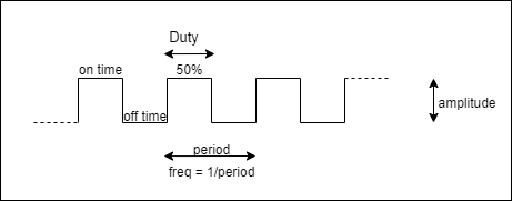
Basic structure of a PWM signal:
Period: Time from one rising edge to the next. A frequency of 100Hz means there are 100 cycles per second.
Duty Cycle: The proportion of time the PWM signal remains high during one period. Duty cycle is usually expressed as a percentage. For example, at 50% duty cycle, the signal is high for half the period and low for the other half.
Frequency: The number of times the PWM signal repeats per second. Frequency is inversely proportional to period: Frequency = 1 / Period.
Functional Principle
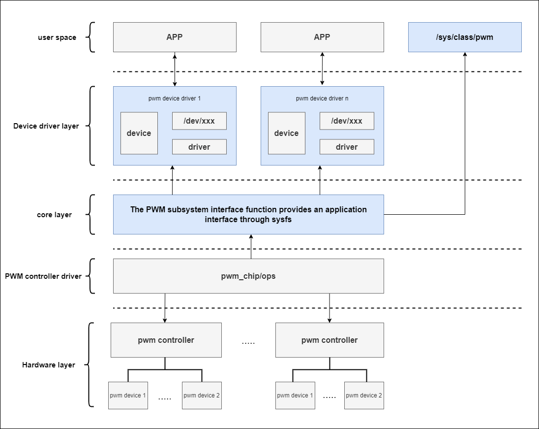
The figure below shows the PWM subsystem architecture, which can be roughly divided into three layers: user layer, core layer, and hardware layer.
Operation Mode
The generation and control process of a PWM signal consists of several steps:
Device Initialization: The driver initializes the PWM hardware via device tree or platform code and configures the hardware registers.
PWM Configuration: Set the PWM period (frequency) and duty cycle via
drobot_pwm_applyor user-space interfaces.Enable PWM: Call
pwm_enable()to start PWM output. Once enabled, the hardware controller generates the PWM waveform according to the specified frequency and duty cycle.Runtime Adjustment: The duty cycle and frequency of the PWM can be adjusted in real time through system interfaces.
Disable PWM: When PWM output is no longer needed, call
pwm_disable()to stop the output.
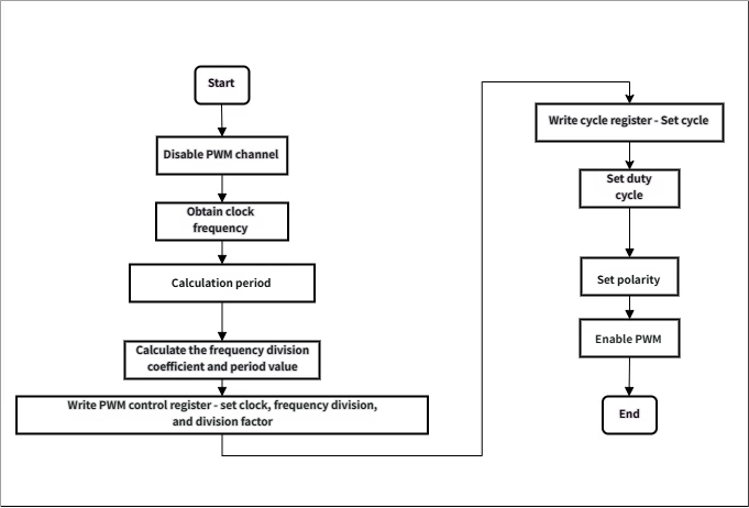
The detailed flow is shown below:
4.3.11.4. Driver Code
PWM Code Description
drivers/pwm/pwm-drobot.c
Kernel Configuration
/* arch/arm64/configs/hobot_x5_soc_defconfig */
...
CONFIG_PWM_DROBOT=y
...
DTS Node Configuration
The X5 PWM controller device tree definition is located in the file arch/arm64/boot/dts/hobot/x5.dtsi under the kernel directory. To enable a specific PWM port output, modify the corresponding board-level file. Here we use x5-evb.dts as an example to enable pwm3 ch0-1.
Note: Nodes in x5.dtsi mainly declare SoC-specific common features and are not related to specific circuit boards; they generally should not be modified.
/* arch/arm64/boot/dts/hobot/x5-evb.dts */
...
&pwm3 {
	status = "okay";
	pinctrl-names = "default";
	pinctrl-0 = <&pinctrl_pwm3_0 &pinctrl_pwm3_1>;
};
...
Explanation of PWM device tree nodes:
&pwm3: This refers to another PWM controller, PWM3.status = "okay": Enables the PWM3 controller.pinctrl-names = "default": Specifies the use of default pin control settings, enabling two channels of PWM3 here.pinctrl-0 = <&pinctrl_pwm3_0 &pinctrl_pwm3_1>: Enables both channels of PWM3.Specifies the pin configuration for the PWM3 controller. This is an array of pointers referencing a series of pin control configurations (typically managed by the pinctrl subsystem). Each
pinctrl_pwm3_Xrepresents a predefined pin configuration that controls the behavior of the PWM signal on physical pins, such as pin number, multiplexing function, power domain configuration, etc.
4.3.11.5. Function Usage
Kernel Space
The drobot_pwm_probe function is an initialization function for a device driver, part of the platform_driver’s probe operation. It executes when the device is detected and the driver is loaded, used to initialize the PWM module’s hardware resources and configure the platform device.
static int drobot_pwm_probe(struct platform_device *pdev)
{
	struct drobot_pwm_chip *drobot_pwm = NULL;
	struct resource *res = NULL;
	int ret = 0;

	drobot_pwm = devm_kzalloc(&pdev->dev, sizeof(*drobot_pwm), GFP_KERNEL);
	if (!drobot_pwm)
		return -ENOMEM;

	res = platform_get_resource(pdev, IORESOURCE_MEM, 0);

	drobot_pwm->base = devm_ioremap_resource(&pdev->dev, res);

	if (IS_ERR(drobot_pwm->base))
		return PTR_ERR(drobot_pwm->base);

	drobot_pwm->clk = devm_clk_get(&pdev->dev, NULL);
	if (IS_ERR(drobot_pwm->clk))
		return PTR_ERR(drobot_pwm->clk);

	ret = clk_prepare_enable(drobot_pwm->clk);
	if (ret < 0) {
		clk_disable_unprepare(drobot_pwm->clk);
		dev_err(&pdev->dev, "failed to enable pwm clock, error %d\n", ret);
		return ret;
	}

	drobot_pwm->reset = devm_reset_control_get_exclusive(&pdev->dev,
						       NULL);
	if (IS_ERR(drobot_pwm->reset))
		return PTR_ERR(drobot_pwm->reset);
	reset_control_assert(drobot_pwm->reset);
	usleep_range(1, 2);
	reset_control_deassert(drobot_pwm->reset);

	drobot_pwm->chip.dev = &pdev->dev;
	drobot_pwm->chip.ops = &drobot_pwm_ops;
	drobot_pwm->chip.npwm = 2;
	drobot_pwm->chip.base = -1;

	ret = pwmchip_add(&drobot_pwm->chip);
	if (ret < 0) {
		dev_err(&pdev->dev, "failed to add PWM chip, error %d\n", ret);
		return ret;
	}

	/* When PWM is disabled, configure the output to the default value */
	platform_set_drvdata(pdev, drobot_pwm);
	pm_runtime_enable(&pdev->dev);

	dev_info(&pdev->dev, "D-Robotics PWM register done!\n");

	return 0;
}
Key Interfaces in Driver Code
1. devm_kzalloc
Purpose: Allocates memory for the
drobot_pwm_chipstructure and manages resources using kernel’s device-managed memory (devm).Parameters: First parameter is the device object (
&pdev->dev), second is the size of memory to allocate, third is the allocation flag (GFP_KERNEL).Return Value: Returns the allocated memory address; returns NULL if allocation fails.
2. platform_get_resource
Purpose: Extracts a specified type of resource from the platform device; here it extracts memory resources (
IORESOURCE_MEM).Parameters: First is the platform device object
pdev, second is the resource type (memory), third is the resource index (usually 0).Return Value: Returns a
struct resourcetype resource structure; returns NULL if the resource does not exist.
3. devm_ioremap_resource
Purpose: Assigns a virtual address to the
basemember in thedrobot_pwm_chipstructure by mapping the device’s physical memory address.Parameters: First is the device object, second is the resource to map.
Return Value: Returns the mapped virtual address; returns ERR_PTR on failure.
4. devm_clk_get
Purpose: Obtains the clock source associated with the device and provides clock support.
Parameters: First is the device object, second is the clock name (here NULL, indicating default clock).
Return Value: Returns the clock handle; returns ERR_PTR if failed.
5. clk_prepare_enable
Purpose: Prepares and enables the clock before activating the device clock, ensuring it is in active state.
Parameter: Clock handle.
Return Value: Returns result of enable operation; negative value indicates failure.
6. devm_reset_control_get_exclusive
Purpose: Acquires and manages the reset control resource associated with the device.
Parameters: First is the device object, second is the reset controller name (here NULL, meaning default reset controller).
Return Value: Returns the reset controller handle; returns ERR_PTR if failed.
7. pwmchip_add
Purpose: Adds the PWM configuration structure of the
drobot_pwmdevice into the kernel for managing PWM outputs.Parameter: PWM configuration structure (
drobot_pwm->chip).Return Value: Negative value indicates failure; 0 indicates success.
8. platform_set_drvdata
Purpose: Stores a pointer to the
drobot_pwmdevice in the platform device for later access.Parameters: Platform device object
pdev, driver data (heredrobot_pwm).Return Value: No return value.
The drobot_pwm_probe function sets drobot_pwm->chip.ops to drobot_pwm_ops, i.e., the PWM operation interface defined in this driver:
static const struct pwm_ops drobot_pwm_ops = {
	.apply = drobot_pwm_apply,
	.owner = THIS_MODULE,
};
It uses drobot_pwm_apply to set duty cycle, period, polarity, etc., and finally calls robot_pwm_enable to enable PWM output.
User Space
Sysfs Node Debugging
When operating PWM on the board, use the cat command to read the device/uevent file under pwmchip to check whether the current pwmchip address matches the target PWM address. Taking pwmchip0 as an example, run the following command on the board to view the uevent of pwmchip0:
cat /sys/class/pwm/pwmchip0/device/uevent
DRIVER=drobot-pwm
OF_NAME=pwm
OF_FULLNAME=/soc/a55_apb0/pwm@34160000
OF_COMPATIBLE_0=d-robotics,pwm
OF_COMPATIBLE_N=1
MODALIAS=of:NpwmT(null)Cd-robotics,pwm
Check the PWM controller node in x5.dtsi as follows:
pwm2: pwm@34160000 {
	compatible = "d-robotics,pwm";
	status = "disabled";
	reg = <0x34160000 0x10000>;
	interrupt-parent = <&gic>;
	interrupts = <GIC_SPI 97 IRQ_TYPE_LEVEL_HIGH>;
	clocks = <&hpsclks X5_LSIO_PWM2_PCLK>;
	#pwm-cells = <2>;
	resets = <&socrst LSIO_PWM2_APB_RESET>;
};
It can be seen that the address of pwmchip0 is 0x34160000, and the address of PWM2 in DTS is also 0x34160000, so PWM2 corresponds to pwmchip0.
root@buildroot:/sys/class/pwm# ls
pwmchip0  pwmchip2  pwmchip6
These devices correspond respectively to pwmchip0 – PWM0, pwmchip2 – lPWM0. Enter the pwmchip0 device, the following nodes are available:
root@buildroot:/sys/class/pwm# cd pwmchip0
root@buildroot:/sys/class/pwm/pwmchip0# ls
device  export  npwm  power  subsystem  uevent  unexport
device: A symbolic link pointing to the actual hardware device node. Accessing this file allows the system to retrieve or modify attributes related to the device.
npwm: Indicates the number of channels in the current PWM; the number of PWM channels is 2.
export: Users can write the channel number to the export file to expose it to
/sys/class/pwm/pwmchip0/pwmXdirectory (X is the PWM channel number).power: Provides information related to device power management, such as whether power-saving mode is enabled or power is on.
subsystem: A symbolic link pointing to the subsystem to which this PWM device belongs. Subsystems are part of Linux’s device management hierarchy, representing the category of the device (e.g., PWM, I2C).
uevent: Used to manage udev (device manager) events, typically notifying the system of device changes.
unexport: Allows users to write to cancel the export of a PWM channel. If a channel has been exported (via export), writing its number to unexport removes it, making the channel unavailable.
You can use echo to set parameters like period and duty_cycle. Note: The Linux PWM framework uses nanosecond precision. Input values are rounded to the nearest microsecond before being written to registers. Therefore, input values for period/duty_cycle should be multiplied by 1000.
Request and register channel PWM0:
root@buildroot:/sys/class/pwm/pwmchip0# echo 0 > export
root@buildroot:/sys/class/pwm/pwmchip0# cd pwm0
Set period to 100μs:
root@buildroot:/sys/class/pwm/pwmchip0/pwm0# echo 100000 > period
Set duty cycle to 50%:
root@buildroot:/sys/class/pwm/pwmchip0/pwm0# echo 50000 > duty_cycle
Enable or disable PWM output:
root@buildroot:/sys/class/pwm/pwmchip0/pwm0# echo 1 > enable
root@buildroot:/sys/class/pwm/pwmchip0/pwm0# echo 0 > enable
Users can refer to the following script to read PWM registers and verify if PWM is working properly. Taking pwmchip0 ch0 as an example:
#!/bin/bash
set -e

target_chip="pwmchip0"
target_ch="0"
chip_sysfs_path="/sys/class/pwm/${target_chip}"
ch_sysfs_path="${chip_sysfs_path}/pwm${target_ch}"

cd "$chip_sysfs_path" || { echo "$chip_sysfs_path not found! Abort!"; exit 1; }
if [ ! -d "$ch_sysfs_path" ];then
	echo "$target_ch" > export
fi
cd "pwm${target_ch}"

# Configure period as 100μs
echo 100000 > period
# Configure duty cycle as 50% = 100μs * 0.5 = 50μs
echo 50000 > duty_cycle
# Enable PWM output
echo 1 > enable

# Read registers below
chip_reg="0x$(cat ${chip_sysfs_path}/device/uevent | grep OF_FULLNAME | awk -F'@' '{print $2}')"
echo "Regs of ${target_chip}:"
echo "PWM_EN       `devmem $(printf "0x%X" $((chip_reg + 0x00))) 32`"
echo "PWM_INT_CTRL `devmem $(printf "0x%X" $((chip_reg + 0x04))) 32`"
echo "PWMCH0_CTRL    `devmem $(printf "0x%X" $((chip_reg + 0x10))) 32`"
echo "PWMCH0_CLK     `devmem $(printf "0x%X" $((chip_reg + 0x14))) 32`"
echo "PWMCH0_PERIOD  `devmem $(printf "0x%X" $((chip_reg + 0x20))) 32`"
echo "PWMCH0_STATUS  `devmem $(printf "0x%X" $((chip_reg + 0x28))) 32`"
echo "PWMCH1_CTRL    `devmem $(printf "0x%X" $((chip_reg + 0x30))) 32`"
echo "PWMCH1_CLK     `devmem $(printf "0x%X" $((chip_reg + 0x34))) 32`"
echo "PWMCH1_PERIOD  `devmem $(printf "0x%X" $((chip_reg + 0x40))) 32`"
echo "PWMCH1_STATUS  `devmem $(printf "0x%X" $((chip_reg + 0x48))) 32`"