4.2. Hardware Bring-Up Guide
Hardware bring-up is the first step in embedded system development, and it is the critical process of transforming hardware design from schematics into a functional physical device. Through the bring-up process, engineers can verify the correctness of the hardware design, run the minimal system for initial testing, and lay the foundation for subsequent feature development. This guide details the fundamental procedures and key steps of hardware bring-up, covering aspects such as minimal system preparation, hardware board inspection and debugging, and initial system functionality verification.
4.2.1. Hardware Bring-Up Basic Process
This section outlines the overall hardware bring-up workflow, providing a clear roadmap for subsequent development. In the following sections, we will elaborate on development tasks involved in each phase to help users complete their development work step by step.
4.2.1.1. Minimal System Preparation
Before the hardware board returns from fabrication, software development can begin in advance to enable rapid validation and debugging once the board arrives.
Board-level configuration and basic driver development
Add a new board-level configuration file (e.g.,
board_xxx_config.mk, wherexxxis a user-defined name such asx5_evb_release) in the BSP code (source located in SDK delivery package atboard_support_package/platform_source_code.tar.gz) to adapt to the new hardware platform.Add the new hardware’s Board ID in U-Boot.
Add relevant configuration files and device trees (DTB) in U-Boot and Kernel, including pin multiplexing settings and functional enable/disable configurations.
Port low-speed bus peripheral drivers (such as UART, I2C, SPI, PWM, etc.) according to the hardware design, ensuring Ethernet and USB drivers are properly adapted.
Plan the partition table based on product design requirements.
Hardware design review and voltage domain configuration
Confirm voltage domain settings for all functional modules according to the design, ensuring alignment with the actual hardware circuitry.
Caution: Incorrect voltage domain configuration may lead to chip damage or unpredictable device behavior. Extreme care must be taken.
Participants: Primarily software engineers, with hardware engineers providing clarification on hardware specifications.
4.2.1.2. Hardware Board Inspection and Debugging
Hardware inspection
Visual inspection: Ensure no components are missing, misplaced, or have soldering defects.
Power supply check: After powering on, use a multimeter or oscilloscope to measure whether the chip’s power supply is stable and meets design requirements.
Initial functionality verification
Connect to the device via serial port and observe debug serial output logs:
No log output: Focus on checking power supply, reset signals, and clock sources.
Abnormal logs: Diagnose the root cause based on error messages.
Normal logs: For hardware intended to load system images, normal boot behavior includes entering serial download mode, continuously printing the character
Cover the serial interface upon power-up.
System flashing
Flash the minimal system image. Refer to System Image Flashing Guide for detailed instructions.
Participants: Primarily hardware engineers, with software engineers providing the system image and coordinating the flashing process.
4.2.1.3. Troubleshooting Boot Failures
Stuck at miniboot stage
Verify DDR model and capacity are correctly identified, and ensure training parameters succeed.
Confirm the U-Boot loading sequence proceeds without errors.
Stuck at U-Boot stage
Check whether the hardware Board ID is correctly recognized.
Verify Kernel loading parameters (bootargs/cmdline) are correct.
Ensure the correct device tree is being loaded.
Participants: Primarily software engineers, with hardware engineers assisting in clarifying hardware design specifications.
4.2.1.4. System Functionality Verification
Kernel boot verification
Examine kernel boot logs to confirm successful loading of driver modules and initialization of device drivers.
Verify normal mounting of root file system, application (app), and user data partition (userdata).
Functional interface testing
Test network interfaces (e.g., SSH login) and USB port functionality (e.g., ADB connection).
If Ethernet is available on the hardware, ensure the system can enter shell and perform basic operations.
If USB device interface is available, ensure the system can enter adb shell and perform basic operations.
Participants: Software engineers.
4.2.1.5. System Stability Testing
Stress testing
Perform high-load tests on core hardware components such as CPU, DDR, BPU, eMMC / Nand Flash.
Test performance and stability of specific functional modules based on product requirements.
Participants: Primarily test engineers, with software engineers providing necessary test software and environment setup guidance.
4.2.2. Adding Board-Level Configuration
Board-level configuration refers to the compilation and runtime environment setup files tailored for a specific hardware platform during system development. These configuration files allow developers to define key hardware parameters such as chip model, architecture, cross-compilation toolchain path, partition information, and root file system. They ensure that the build system generates firmware compatible with the target hardware, while simplifying switching and maintenance across different hardware versions.
In scenarios where multiple hardware platforms share a common codebase, each hardware variant requires its own board-level configuration file to enable specific features, load appropriate drivers, and maintain system compatibility and stability.
Below is an example of device/horizon/x5/board_x5_evb_release_config.mk, illustrating the typical structure and settings of a board-level configuration file:
#!/bin/bash

export HR_TARGET_VENDOR="horizon"
export HR_TARGET_CHIP="x5"
export HR_SECURE_CHIP=y
export HR_TARGET_BIT="64"
export HR_TARGET_MODE="release"

# Board type, corresponding to each new hardware model
export HR_BOARD_TYPE="soc"

# Output directory for compilation
export HR_BUILD_OUTPUT_DIR=${HR_TOP_DIR}/out
# Intermediate build directory (e.g., for uboot, kernel, hbre)
export HR_TARGET_BUILD_DIR=${HR_BUILD_OUTPUT_DIR}/build
# Output path for generated images (used for flashing and release)
export HR_TARGET_PRODUCT_DIR=${HR_BUILD_OUTPUT_DIR}/product
# Intermediate artifacts from build to product (e.g., kernel, device tree, rootfs)
export HR_TARGET_DEPLOY_DIR=${HR_BUILD_OUTPUT_DIR}/deploy
# Compilation log storage directory
export HR_BUILD_LOG_DIR=${HR_BUILD_OUTPUT_DIR}/build_log

# Directory for board configuration files
export HR_BOARD_CONF_DIR=${HR_TOP_DIR}/"device/horizon/${HR_TARGET_CHIP}/board_cfg/${HR_BOARD_TYPE}"

# Configure cross-compilation toolchain
export ARCH="arm64"
export TOOLCHAIN_PATH=/opt/arm-gnu-toolchain-11.3.rel1-x86_64-aarch64-none-linux-gnu
export CROSS_COMPILE=${TOOLCHAIN_PATH}/bin/aarch64-none-linux-gnu-

# Enable ccache to accelerate compilation
export HR_CCACHE_SUPPORT=y
export CCACHE_COMMAND="ccache"
export HR_APPEND_CXX_OPTIONS="-DCMAKE_CXX_COMPILER=\"${CCACHE_COMMAND}\" -DCMAKE_CXX_COMPILER_ARG1=\"${CROSS_COMPILE}g++\" -DCMAKE_C_COMPILER=\"${CCACHE_COMMAND}\" -DCMAKE_C_COMPILER_ARG1=\"${CROSS_COMPILE}gcc\""
export HR_CCACHE_DIR="$HOME/.ccache"

# Path for commonly used build tools (e.g., fiptool)
export HR_BUILD_TOOL_PATH=${HR_TOP_DIR}/build/tools
# Path for partition table tools (MBR, GPT processing)
export HR_PARTITION_TOOL_PATH=${HR_TOP_DIR}/build/tools/partition_tools
# Path for AVB tools scripts, used for adding verification info to kernel and partitions (mk_system.sh)
export HR_AVB_TOOLS_PATH=${HR_TOP_DIR}/build/tools/android_tools/avbtools
export HR_BD_IMG_TOOLS_PATH=${HR_TOP_DIR}/build/tools/android_tools/build_image

# Partition table configuration file directory and filename
export HR_PART_CONF_FILENAME=${HR_BOARD_CONF_DIR}/x5-soc-release-gpt.json
export BLK_SZ=512
export MMC_UFS_ERASE_SIZE=524288
export NOR_ERASE_SIZE=32768
export HYPER_ERASE_SIZE=262144

# U-Boot compilation configuration file
export HR_UBOOT_CONFIG_FILE=hobot_x5_auto_defconfig
export HR_ARCH_UBOOT="arm"
# Specify output directory for U-Boot source; if not set, compilation occurs in source directory
export HR_UBOOT_OUTPUT_DIR=${HR_TARGET_BUILD_DIR}/uboot

# Kernel configuration
# Kernel compilation configuration file
export HR_KERNEL_CONFIG_FILE=hobot_x5_soc_perf_defconfig
export HR_ARCH_KERNEL="arm64"
# Specify output directory for kernel source; if not set, compilation occurs in source directory
export HR_KERNEL_OUTPUT_DIR=${HR_TARGET_BUILD_DIR}/kernel

# System configuration
# Specify root filesystem type and prebuilt filesystem path
export HR_SYSTEM_TYPE="buildroot"
export HR_SYSTEM_DIR=${HR_TOP_DIR}/system/buildroot/prebuilt
# Root filesystem partition name, must match partition table configuration
export HR_SYSTEM_PART_NAME="system"
# System verification method: dm-verity, crypt
export HR_SYSTEM_VERIFY="dm-verity"

# Set SDK version
source "${HR_TOP_DIR}/device/${HR_TARGET_VENDOR}/${HR_TARGET_CHIP}/dr_release_version.mk"
export HR_BUILD_VERSION="${HR_RELEASE_VERSION}"

# Anti-rollback version
export ANTIROLLBACK_SEC_UPDATE="false"
export ANTIROLLBACK_SEC_VER=0
export ANTIROLLBACK_NOSEC_UPDATE="false"
export ANTIROLLBACK_NOSEC_VER=0

# Flag indicating board configuration environment variables have been set
export HR_IS_BOARD_CONFIG_EXPORT="true"
4.2.2.1. Key Configuration Items Explained
Target hardware information
HR_TARGET_VENDORandHR_TARGET_CHIPdefine the vendor and chip model of the target hardware.HR_BOARD_TYPEdistinguishes specific board types.
Build output paths
HR_BUILD_OUTPUT_DIRis the root directory for all build artifacts;HR_TARGET_PRODUCT_DIRstores final image outputs.
Toolchain configuration
CROSS_COMPILEsets up the cross-compilation toolchain, specifying architecture and tool paths.
Partition table selection
HR_BOARD_CONF_DIRandHR_PART_CONF_FILENAMEspecify the partition table configuration file used.
Module configuration
Includes compilation configuration files and paths for U-Boot, Kernel, and system partition tables.
Optimization and tool support
Enabling
ccacheaccelerates compilation; defined tool paths facilitate access to build and partition tools.
4.2.2.2. Partition Configuration
Partition table configuration is specified via key options HR_BOARD_CONF_DIR and HR_PART_CONF_FILENAME:
# Directory for board configuration files
export HR_BOARD_CONF_DIR=${HR_TOP_DIR}/"device/horizon/${HR_TARGET_CHIP}/board_cfg/${HR_BOARD_TYPE}"

# Directory and filename for partition table configuration
export HR_PART_CONF_FILENAME=${HR_BOARD_CONF_DIR}/x5-soc-release-gpt.json
The partition table defines the data layout on storage devices, including critical partitions such as system, user data, and boot partitions. When developing new hardware, the partition table configuration file should be adjusted according to hardware characteristics and product requirements.
Partition Table File Description
Partition table files are located under device/horizon/x5/board_cfg/*, typically ending with gpt.json.
Example: device/horizon/x5/board_cfg/soc/x5-soc-release-gpt.json
{
        "gpt": {
                "size": "20k"
        },
        "mbr": {
                "size": "4k"
        },
        "miniboot": "sub_config/miniboot.json",
        "misc": {
                "size": "4k"
        },
        "uboot": {
                "part_type": "GOLDEN",
                "size": "2m"
        },
        "ubootenv": {
                "size": "256k"
        },
        "vbmeta": {
                "part_type": "GOLDEN",
                "size": "16k"
        },
        "boot": {
                "part_type": "GOLDEN",
                "size": "12m"
        },
        "system": {
                "fs_type": "ext4",
                "part_type": "GOLDEN",
                "size": "250m"
        },
        "hbre": {
                "fs_type": "ext4",
                "part_type": "GOLDEN",
                "size": "200m"
        },
        "app": {
                "fs_type": "ext4",
                "part_type": "GOLDEN",
                "size": "700m"
        },
        "private": {
                "fs_type": "ext4",
                "part_type": "GOLDEN",
                "size": "256k"
        },
        "userdata": {
                "fs_type": "ext4",
                "size": "50m"
        }
}
Partition Field Descriptions:
gpt: Location where the GPT partition table image is stored. U-Boot, Kernel, and user-space tools like
partedandfdiskread this to obtain the system’s partition layout.mbr: Stores partition information interpretable by ROMCODE, recording locations of BL2, DDR parameters, BL3x, and other firmware within the image.
miniboot: This is a subset definition; internal partitioning of
miniboot.imgis defined insub_config/miniboot.json. Users should not modify this, as it may lead to unnecessary adaptation work.misc: Stores runtime update information and, in A/B partition mode, records the currently active partition index.
uboot: Must be named with a prefix
ubootoru-bootimmediately after the miniboot partition. The overall packaging of the miniboot image relies on this partition name as a boundary.ubootenv: Stores U-Boot environment variables when
saveenvis executed in U-Boot.boot, system, vbmeta: The
vbmetapartition stores AVB verification data forbootandsystem. When secure boot is enabled, these three partitions must be updated together. If users wish to rename them, corresponding code in U-Boot must be modified, and mount configurations in the root filesystem (viahb-fstab) must be adjusted accordingly.Other partitions: Can be adjusted according to actual product needs.
Mandatory Attributes:
fs_type: Defines the file system type of the partition image. Required. Options include:
raw/null: Raw binary data.
ext4/fat32: Specific file system types.
size: Total space occupied by the partition (units: k, m, g). Must be aligned: 64KB for NOR Flash, 4KB for eMMC. Total partition size must equal sum of component sizes.
Optional Attributes (can be omitted):
part_type: Defines partition update type. Options:
AB: Dual partition, for A/B system updates.
BAK: Backup partition, used if primary fails — enhances system reliability.
GOLDEN: Single partition, standard update.
PERMANENT: Permanent partition, never updated. Default if not specified.
ota_is_update: Whether the partition supports OTA updates.
true: Supports OTA.
false: Does not support OTA. Default if not specified.
ota_update_mode: OTA update method (only if
ota_is_update=true).image: Full image update.
medium: Storage medium for the partition image.
fde_type: Encryption method for user partitions. Options:
key-file: Use key file for direct encryption/decryption. See User Partition Encryption: key-file Scheme
Note
To add a new partition on NAND, use UBI-formatted partitions. UBI images are normally output to out/product/. If OTA support is required, output volume images and UBI config files to out/deploy/ubi/. Volume image suffixes can be {volume_name}.bin|.img|.ubifs, and config file name should be {ubi_partition_name}.cfg.
4.2.2.3. U-Boot Option Configuration
The board-level configuration file board_xxx_config.mk specifies the U-Boot configuration file to use. Relevant settings are configured in Board-Level Configuration File as follows:
# Suggestion: When adding new hardware, always add corresponding HR_BOARD_TYPE, HR_UBOOT_CONFIG_FILE, HR_KERNEL_CONFIG_FILE, and DTS device tree files for U-Boot and Kernel

# U-Boot compilation configuration file
export HR_UBOOT_CONFIG_FILE=hobot_x5_auto_defconfig
export HR_ARCH_UBOOT="arm"
# Specify output directory for U-Boot source; if not set, compile in source directory
export HR_UBOOT_OUTPUT_DIR=${HR_TARGET_BUILD_DIR}/uboot
To ensure system compatibility, it is recommended to create dedicated U-Boot configuration and device tree files for each new hardware. These files are located in the U-Boot source tree at:
Configuration files:
configs/Device tree files:
arch/arm/dts/
It is recommended to update the following when introducing a new SoM (System-on-Module):
HR_UBOOT_CONFIG_FILE(U-Boot config)U-Boot device tree file
4.2.2.4. Kernel Option Configuration
The board-level configuration file board_xxx_config.mk specifies the Kernel configuration file. Relevant settings are configured in Board-Level Configuration File as follows:
# Kernel compilation configuration file
export HR_KERNEL_CONFIG_FILE=hobot_x5_soc_perf_defconfig
export HR_ARCH_KERNEL="arm64"
# Specify output directory for kernel source; if not set, compile in source directory
export HR_KERNEL_OUTPUT_DIR=${HR_TARGET_BUILD_DIR}/kernel
To ensure system compatibility, it is recommended to create dedicated Kernel configuration and device tree files for each new hardware. File paths are:
Configuration files:
arch/arm64/configs/Device tree files:
arch/arm64/boot/dts/hobot/
When adding new hardware, ensure the following are updated:
HR_KERNEL_CONFIG_FILE(Kernel config)Kernel device tree file
4.2.3. Adding New Hardware in U-Boot
When adapting firmware for a new hardware model, the following steps ensure one software firmware can support multiple hardware platforms:
Define a new Board ID
Assign a unique Board ID to the new hardware to distinguish different platforms in the system. On the X5 platform, the Board ID is defined via 4 ADC channels, using different external voltage values for hardware identification. This ID is used during system boot to determine the current hardware configuration and load corresponding firmware or drivers.
For more details, refer to Hardware Board ID Overview.
Note: During U-Boot debugging, users may choose to define the Board ID in software instead of relying on hardware ADC channels. This approach facilitates hardware adaptation and debugging during development and testing.
Porting in U-Boot
Adapt U-Boot to the new hardware by modifying or adding configuration files. Specific porting tasks include:
Create a new U-Boot configuration file.
Add or modify hardware-specific device tree (Device Tree) files to support peripherals and features of the new hardware.
These steps ensure that a single firmware image can run correctly across multiple hardware platforms, simplifying development and maintenance across different hardware variants.
4.2.3.1. Hardware Board ID Overview
On the X5 platform, the Board ID is defined via 4 ADC channels, using different external voltage values for hardware identification. Current ADC channel (ADC_VINS) configurations are as follows:
ADC_VINS0: Mainboard type — different X5 projects use different IDs. For example, if a user has two internal X5 project lines, they can use different resistor dividers on VIN0 to distinguish them.
ADC_VINS1: Used to differentiate hardware versions within a project line (e.g., First hardware release, second hardware release.).
ADC_VINS2: DDR parameter configuration. Users must strictly follow the official hardware reference design when selecting the appropriate setting based on the motherboard’s DDR BOM.
ADC_VINS6: Reserved setting; recommended to leave NC. If additional ADC is needed, prefer other ADC channels (ADC_VIN).
Hardware Board ID circuit design requires a 100nF decoupling capacitor and appropriate voltage divider resistors to ensure accurate ADC voltage readings.
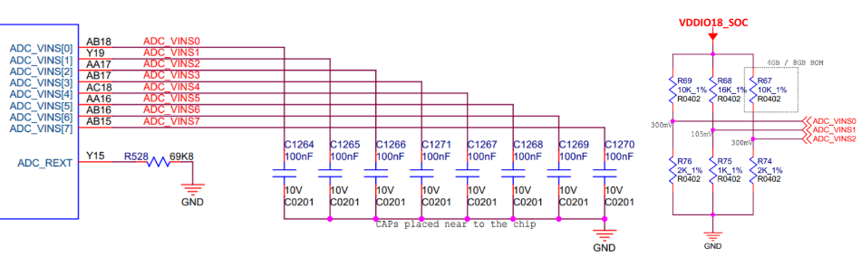
Selection of External Voltage Divider Resistors:
Refer to the official hardware reference design for pull-up/pull-down resistor selection. Total resistance should not exceed 50KΩ. High-value resistors (especially above 100KΩ) may cause:
High resistance leads to noticeable RC effects in internal ADC sampling, reducing accuracy.
Higher susceptibility to noise.
Most ADC applications stay below 50KΩ; values above 100KΩ are rare.
Example resistor combinations:
| Analog Voltage | R1 | R2 | Tolerance |
|---|---|---|---|
| 100mV | 16K | 1K | 1% |
| 200mV | 16K | 2K | 1% |
| 300mV | 10K | 2K | 1% |
| 400mV | 23.7K | 6.8K | 1% |
| 500mV | 5.1K | 2K | 1% |
ADC Voltage Level Design Guidelines:
Users are advised to use the reference voltage levels provided in this section and avoid custom voltage ranges. That is, each level should be 100mV, 200mV, etc. Thus, each field supports up to 17 levels (ADC voltage range 0.1V ~ 1.7V).
The software mapping of each analog voltage (e.g., 100mV mapped to ID=1 in software) is user-defined and not strictly enforced.
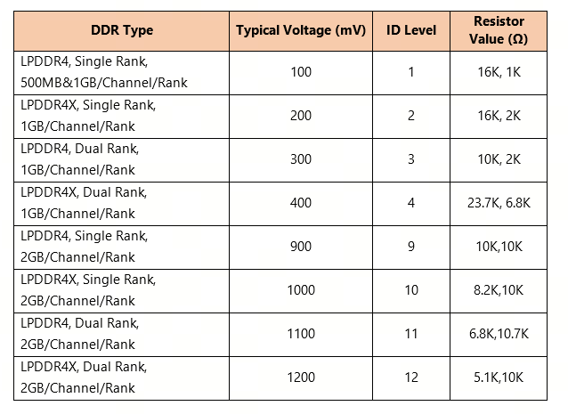
ADC_VINS2 is strictly constrained and related to DDR Type:
The X5 platform supports a total bus width of 32 bits, using a 2-channel design, each channel 16 bits wide (i.e., 2CH x 16 = 32 bits). Each die in the DDR chip must have a x16 width. Design must ensure DDR frequency and capacity meet platform performance requirements, with careful PCB layout for signal integrity and length matching to ensure system stability and compatibility.
X5 supports both LPDDR4 and LPDDR4X modes, and both single-rank and dual-rank configurations, distinguished via ADC_VINS2.
ADC_VINS2 levels do not reflect DDR capacity; supported capacities include 1GB, 2GB, 4GB, and 8GB.
For supported models, refer to Approved Vendor List.
Important: Configure level values from 1 to 17. Do not directly pull ADC input low (level 0) or high to power (level 18).
ADC sampling range, divider values, and level assignment reference:
4.2.3.2. Adding a New U-Boot Configuration File
Using the creation of a new hardware called som as an example, the following steps detail the development and porting process:
Enter U-Boot source tree
Navigate to the U-Boot source directory and go to the
configssubdirectory.Copy base configuration file
Use the existing
hobot_x5_auto_defconfigas a base to generate a dedicated config for the new hardware. For a SoM namedsom, name the new filehobot_x5_som_defconfig:cd configs cp hobot_x5_auto_defconfig hobot_x5_som_defconfig
Modify configuration options
Edit
hobot_x5_som_defconfigaccording to the new hardware’s design requirements, adjusting settings such as boot parameters, storage interfaces, and peripheral support to match hardware features.
4.2.3.3. Adding a New Software Board ID Definition
When adapting new hardware, assign a unique Board ID to distinguish different platforms. The Hardware Board ID is read from ADC channel voltage values. To enhance flexibility, the system also defines a Software Board ID, which maps to the Hardware Board ID.
Using a new hardware named som as an example, the steps to add a new Software Board ID are:
Modify Kconfig File
In drivers/horizon/Kconfig, add a choice option for the new hardware’s Board ID. Example:
config HOBOT_X5_SOM
        bool "X5SOM"
        help
          Select this option for Board Type X5 SOM.
This allows selecting the new hardware type X5 SOM at compile time.
Modify Board ID Macro Definitions
In include/dt-bindings/board/hb_board_id.h:
Add macro definition for new Software Board ID
Assign a unique ID, e.g.:
#define HOBOT_X5_SOM_ID 0x2000Add macro condition check
Bind the new macro to its configuration option to ensure correct Board ID loading. Example:
#if defined(CONFIG_HOBOT_X5_FPGA)
    #define HOBOT_X5_BOARD_ID HOBOT_X5_FPGA_ID
#elif defined(CONFIG_HOBOT_X5_EVB)
    #define HOBOT_X5_BOARD_ID HOBOT_X5_EVB_ID
#elif defined(CONFIG_HOBOT_X5_SOM)
    #define HOBOT_X5_BOARD_ID HOBOT_X5_SOM_ID
#elif !defined(CONFIG_HOBOT_ADC_BTYPE)
    #define CONFIG_HOBOT_ADC_BTYPE
#endif
Avoid Software Board ID Conflicts
Official BSP uses Software Board IDs in the range 0x0000 ~ 0x1FFF. To avoid conflicts with future BSP updates, users should avoid this range and use 0x2000 or higher.
Verify Added Content
Use git diff to review code changes and ensure additions are correct and complete. Example:
diff --git a/include/dt-bindings/board/hb_board_id.h b/include/dt-bindings/board/hb_board_id.h
index 8ed2b921ee..b12f4b5505 100644
--- a/include/dt-bindings/board/hb_board_id.h
+++ b/include/dt-bindings/board/hb_board_id.h
@@ -13,6 +13,7 @@
 #define HOBOT_X5_EVB_ID    0x0201
 #define HOBOT_X5_EVB_V2_ID 0x0202
 #define HOBOT_X5_RDK_ID    0x0301
+#define HOBOT_X5_SOM_ID    0x2000

 #if defined(CONFIG_HOBOT_X5_FPGA)
     #define HOBOT_X5_BOARD_ID HOBOT_X5_FPGA_ID
@@ -24,6 +25,8 @@
     #define HOBOT_X5_BOARD_ID HOBOT_X5_EVB_ID
 #elif defined(CONFIG_HOBOT_X5_EVB_V2)
     #define HOBOT_X5_BOARD_ID HOBOT_X5_EVB_V2_ID
+#elif defined(CONFIG_HOBOT_X5_SOM)
+    #define HOBOT_X5_BOARD_ID HOBOT_X5_SOM_ID
 #elif !defined(CONFIG_HOBOT_ADC_BTYPE)
     #define CONFIG_HOBOT_ADC_BTYPE
 #endif
Relationship Between Hardware Board ID and Software Board ID
Hardware Board ID is a unique identifier read from the voltage value on an ADC channel, used during boot to identify the hardware platform.
Software Board ID is a software-defined identifier defined during development and compilation, which maps to the hardware Board ID.
This approach enables flexible adaptation to different hardware platforms by combining hardware and software Board IDs, while supporting customized feature development.
4.2.3.4. Adding Device Tree in U-Boot
Taking the creation of a new hardware called som as an example, the steps to add device tree definitions are as follows:
Create Device Tree File
Enter the U-Boot device tree directory arch/arm/dts, copy the existing x5-soc.dtsi file and rename it to x5-som.dtsi:
cd arch/arm/dts
cp x5-soc.dtsi x5-som.dtsi
Modify the following content in the new file x5-som.dtsi:
Change the value of the
supported-btypenode toHOBOT_X5_SOM_ID(the definition added in the “Adding Software Board ID” section).
btype-dev = &board_type;
supported-btype =
        <
        HOBOT_X5_SOM_ID
        >;
Replace all instances of
x5_socin thex5-som.dtsifile withx5_som.
Include New File in Main Device Tree
Include the newly added x5-som.dtsi file into the main device tree file arch/arm/dts/x5.dtsi. Add the following line at the end of the file:
#include "x5-soc.dtsi"
#include "x5-som.dtsi"
Modify board_type Configuration
In the arch/arm/dts/x5.dtsi file, update the board_type node to support the new hardware Board ID, as follows:
Add a new entry for
HOBOT_X5_SOM_IDin theboard_type_array. For example, add<51 140 151 240 HOBOT_X5_SOM_ID 5 0 0 1 4>:board_type: board_type { compatible = "hobot,btype"; adc_dev = &adc, &adc; adc_channel = <0 1>; board_type_array = ... ( omitted ) ... <51 140 151 240 HOBOT_X5_SOM_ID 5 0 0 1 4>, ... ( omitted ) ... hardware_array = "x5-fpga", "x5-soc", "x5-svb", "X5_EVB_LP4", "X5_EVB_LP4X", "X5-SOM"; ethact_array = "default"; net_eth0_ipaddr = "192.168.1.10"; pmic_type = "dual-pmic", "single-pmic"; board_version = "1_A", "1_B", "V1P2", "V1P3", "V0P1"; };
Ensure that the corresponding hardware name
"X5-SOM"is added inhardware_array:hardware_array = "x5-fpga", "x5-soc", "x5-svb", "X5_EVB_LP4", "X5_EVB_LP4X", "X5-SOM";
The fields in board_type_array have the following meanings:
The first 4 bytes define the voltage range on the ADC channel, used for hardware identification:
51 140: Voltage range (51 ~ 140 mV) for theADC_VINS0channel, used to distinguish hardware types. The hardware voltage divider circuit scales the voltage to around 100 mV; this range accommodates possible voltage fluctuations.151 240: Voltage range (151 ~ 240 mV) for theADC_VINS1channel, used to distinguish hardware versions. The hardware voltage divider scales the voltage to around 200 mV; this range accounts for fluctuations.
The 5th byte represents the software Board ID (
HOBOT_X5_SOM_ID)The binding logic between hardware and software Board ID is as follows:
If the U-Boot option
CONFIG_HOBOT_ADC_BTYPEis enabled, the system uses thehb-btype.cdriver to read the voltage values from the board’s ADC channels and matches them against the voltage ranges defined in the device tree’sboard_type_arrayto determine the hardware type and version. Upon successful match, the hardware Board ID is mapped to the corresponding software Board ID for subsequent device identification and adaptation.For example, for the
board_type_arrayentry<51 140 151 240 HOBOT_X5_SOM_ID 5 0 0 1 4>, when the hardware’sADC_VINS0reads a voltage within 51–140 mV andADC_VINS1reads within 151–240 mV, the system identifies the hardware asHOBOT_X5_SOM_ID.
Meaning of Other Fields
Starting from
HOBOT_X5_SOM_ID, each field corresponds to an index in different hardware configuration arrays:Hardware model name (
hardware_array)Ethernet configuration (
ethact_array)IP address (
net_eth0_ipaddr)Whether the hardware uses single or dual PMIC (
pmic_type), most cases usesingle-pmicHardware version (
board_version)
For example, in
<51 140 151 240 HOBOT_X5_SOM_ID 5 0 0 1 4>, the number5corresponds toX5-SOMinhardware_array; other fields follow the same logic.
Notes
String Length Limitation
Strings in
hardware_arrayandboard_versionare passed to the kernel’s device tree, affecting the following fields in thesocinfodriver:hw_nameboard_versionhw_info
Ensure that string lengths do not exceed placeholder limits in the kernel, otherwise the
socinfodriver may fail to load.Required Adjustments
If string lengths exceed the limit, update the kernel’s device tree placeholders accordingly. Refer to the boardinfo debugging guide.
4.2.3.5. Applying Board ID in U-Boot Configuration
After defining the new hardware’s Board ID, configuration files, and modifying the device tree, reconfigure U-Boot to set the CONFIG_HOBOT_X5_SOM macro to the new Board ID. Follow the steps below:
Use the New Configuration File
Run the following commands to load the configuration file for the new hardware:
make ARCH=arm hobot_x5_som_defconfig
make ARCH=arm menuconfig
Location:
  │     -> Device Drivers
    │ (1)   -> Horizon SOC drivers
In the menuconfig interface, navigate to Horizon SOC drivers and select the Board ID corresponding to the new hardware (e.g., HOBOT_X5_SOM) to ensure correct configuration:

Save Configuration
Save the configured options in the menuconfig interface, then use the following commands to save a minimal configuration:
# Use savedefconfig to save minimal configuration
make ARCH=arm savedefconfig

# Compare changes (optional; if using git, skip and use git diff)
diff defconfig configs/hobot_x5_som_defconfig

# After verification, overwrite the source file
cp defconfig configs/hobot_x5_som_defconfig
With the above steps, you have successfully applied the new Board ID to the U-Boot configuration and prepared for hardware adaptation.
4.2.4. Adding Hardware Support in Kernel
Compared to U-Boot, adding hardware support in the Kernel has the following differences and characteristics:
There is no need to redefine the Board ID; definitions from U-Boot are directly inherited.
Device tree configuration in U-Boot is simpler, focusing only on basic initialization and system boot. The Kernel manages full hardware functionality after OS loading, with more detailed configuration files and device trees covering complete peripheral driver support (e.g., GPIO, I2C, SPI, display devices) and enabling/disabling functional modules.
Device tree files in the Kernel can be independently compiled into DTB files, allowing user selection. In U-Boot, all device tree files are included in a single DTB, and drivers are matched based on the hardware Board ID.
4.2.4.1. Add Kernel Configuration File
After entering the kernel source tree, go to the configuration directory arch/arm64/configs, copy the existing hobot_x5_soc_defconfig file and rename it for the new hardware (e.g., hobot_x5_som_defconfig):
cd arch/arm64/configs
cp hobot_x5_soc_defconfig hobot_x5_som_defconfig
Modify configuration options in this file according to product design requirements.
4.2.4.2. Add Device Tree
Kernel device tree files are located in arch/arm64/boot/dts/hobot, with the following directory structure:
.
├── Makefile
├── pinmux-func.dtsi
├── pinmux-gpio.dtsi
├── x5-evb-lp4-1_a.dts
├── x5-evb-lp4-1_b.dts
├── x5-evb-lp4-v1p2.dts
├── x5-evb-lp4-v1p3.dts
├── x5-evb-lp4-v2p0.dts
├── x5-evb-lp4x-v0p1.dts
├── x5-evb.dtsi
├── x5-fpga.dts
├── x5-md-v0p1.dts
├── x5-md-v0p2.dts
├── x5-memory.dtsi
├── x5-rdk-v1p0.dts
├── x5-rdk.dts
├── x5-rdk.dtsi
├── x5-som.dts
├── x5-svb.dts
└── x5.dtsi
pinmux-func.dtsi: Defines function groups for each PIN. Board-level device tree.dtsfiles include it as follows:#include "pinmux-func.dtsi"pinmux-gpio.dtsi: Defines GPIO groups; users can reference specific GPIO groups (PINGRP).x5.dtsi: Defines default configurations for all modules on the X5 platform, serving as a base functional description. Modifying this is not recommended.x5-evb.dtsi: Defines common configurations across different EVB hardware versions, including defaults fromx5.dtsi.x5-<board-level-product>.dts: Board-level device tree files that include default configurations fromx5.dtsi, and enable/disable functional modules and define hardware-specific peripherals. EVB-relateddtsfiles includex5-evb.dtsiand describe differing configurations within the.dtsfile.
Using existing device tree files as templates, create a new device tree file for the new hardware, for example:
cd arch/arm64/boot/dts/hobot
cp x5-evb-lp4-1_b.dts x5-som.dts
Modify the x5-<new_board>.dts file according to the new hardware design to ensure correct peripheral and module configuration.
4.2.4.3. Default Module States
Peripherals and display-related modules are disabled by default.
Image processing and other basic modules are enabled by default.
Low-speed buses are disabled by default; users enable them based on hardware design.
4.2.4.4. Edit Board-Level Device Tree
In the board-level device tree file x5-<board-level-product>.dts:
Include all base dtsi files:
The device tree file must directly include all relevant dtsi files. For example:
#include "x5.dtsi"Configure clock sources and memory layout:
Define clock source frequencies and memory distribution for the current hardware.
Define peripheral and module configurations:
Write specific peripheral and module configurations into corresponding dtsi files, adjusting enable states based on hardware design.
4.2.4.5. Matching Software Board ID with Device Tree (DTB)
In the kernel, the device tree (DTS) must be associated with the Board ID to ensure the system loads the correct device tree for the current hardware. Using the SOM hardware as an example, the following explains how to configure the Board ID to DTB matching.
Configure its File to Add Device Tree
In the kernel image’s fit package, modify the corresponding configuration file at:
device/horizon/x5/board_cfg/soc/boot_its/x5-common.its
Include the new device tree file (e.g.,
x5-som.dtbgenerated fromx5-som.dts) intoboot.img. Add the device tree configuration in theitsfile as follows:/dts-v1/; / { description = "U-Boot FIT for x5"; #address-cells = <1>; images { ... ( omitted ) ... fdt2 { description = "FDT-SOM"; data = /incbin/("x5-som.dtb"); type = "flat_dt"; arch = "arm64"; compression = "none"; /* hash-1 { algo = "sha1"; }; */ }; ... ( omitted ) ... }; ... ( omitted ) ... }In the
configurationssection, associate the Board ID with the device tree:/dts-v1/; / { description = "U-Boot FIT for x5"; #address-cells = <1>; ... ( omitted ) ... configurations { default = "boardid-0x0201"; ... ( omitted ) ... boardid-0xFE01 { description = "x5-som"; kernel = "kernel"; fdt = "fdt2"; }; ... ( omitted ) ... }; };
Notes
Board ID Format:
The configuration item
boardid-0x0201corresponds to the Board ID added in U-Boot, such as the value ofHOBOT_X5_SOM_ID.boardid-0x0201is parsed as a string in U-Boot. If the Board ID contains letters, they must be in uppercase, e.g.,0xff10should be written as0xFF10.
FDT Parameter:
The
fdtfield must match the name of the newly added device tree configuration. For example,boardid-0xFE01usesfdt2, which corresponds tox5-som.dtb.
U-Boot Kernel Boot Process
During system startup, U-Boot selects the appropriate kernel and device tree based on the current hardware’s Board ID. The boot command is:
bootm ${kernel_addr}#boardid-${hb_board_id}
In this command, ${hb_board_id} is the software Board ID of the current hardware. U-Boot matches this ID to the fdt configuration in the its file and loads the correct device tree and kernel.
4.2.5. Debugging Minimal System
After powering on the device, users can check for log output via the debug serial port. If no logs appear, check the following:
Whether chip power supply is normal
Whether BOOTSEL pin configuration is correct
Whether the debug serial port and PC terminal software baud rate match
4.2.5.1. Serial Log in Blank Chip State
When the device is in a blank chip state, the UART log after power-on is as follows, eventually entering DFU download mode:
SNOTICE:  Welcome to Horizon X5 ASIC BOOTROM - V4.1
NOTICE:                 OTP config:
NOTICE:                         otp exist: true
NOTICE:                         test region size: 304
NOTICE:                         secure region size: 120
NOTICE:                         none secure region size: 56
NOTICE:   Enable MMU
NOTICE:  Booting Trusted Firmware
NOTICE:  BL1: v2.8(release):
NOTICE:  BL1: Built : 17:42:12, Oct 19 2023
NOTICE:  Enter eMMC Mode......
NOTICE:  USER AREA.
NOTICE:   eMMC clk_rate = CLK_12_5M
NOTICE:   eMMC emmc_data_width == WIDTH_DATA_1
NOTICE:   eMMC emmc_cfg.emmc_clk_latch == CLK_FALLING
NOTICE:  Enter media_source_select process(1).
ERROR:   horizon_emmc_read_blocks fail!!   checksum = 0x0 (0x0) 0x0
ERROR:    plat_error_handler 0
... ( omitted ) ...
NOTICE:  Enter eMMC Mode......
NOTICE:  USER AREA.
NOTICE:   eMMC clk_rate = CLK_12_5M
NOTICE:   eMMC emmc_data_width == WIDTH_DATA_1
NOTICE:   eMMC emmc_cfg.emmc_clk_latch == CLK_FALLING
NOTICE:  Currtenly use dfu-util to download file
NOTICE:  Download file via USB
NOTICE:  DFU Start...
4.2.5.2. System Flashing
After confirming the device outputs logs correctly, users can flash the pre-built minimal system onto the device. For detailed flashing instructions, refer to: System Image Flashing.
If the system fails to boot after flashing, perform step-by-step debugging based on the failure stage.
4.2.5.3. Debugging Boot Stages
1. miniboot boot failure
miniboot is responsible for DDR initialization (Training), and sequentially loading BL2, BL31, and U-Boot, finally jumping to U-Boot. Possible causes of miniboot boot failure include:
Incorrect image packaging
Failure to recognize or read/write data from eMMC or Nand Flash
DDR Training failure
U-Boot loading failure
2. U-Boot boot failure
U-Boot is used to boot the Linux kernel. Common causes of boot failure:
Kernel partition loading failure
Incorrect cmdline parameter configuration
During debugging, use U-Boot logs to identify the specific issue. Additionally, verify that common modules such as network and USB interfaces are functioning properly based on hardware design.
Verify USB Device Functionality Switch to Fastboot mode in U-Boot and check if the host recognizes the device:
Hobot> fastboot 0
select emmc(0) as flash medium
do fastboot usb
3. Kernel boot failure
If the kernel fails to boot, check the following:
Check kernel boot logs: Confirm that kernel modules and device drivers initialize properly
Check filesystem mount: Confirm that root filesystem,
app, anduserdatapartitions are mounted successfullyCheck terminal login: Confirm the system enters the shell and allows serial login
Check peripheral functionality: Confirm network and USB interfaces are working
4.2.6. System Stability and Stress Testing
After hardware bring-up, perform stability and stress testing on all major modules of the new hardware. For detailed stress test methods, refer to Driver Functional Unit Testing.