2.5. System Image Flashing
2.5.1. Overview
System flashing is the process of writing an operating system, applications, and related data to the storage device (e.g., eMMC or NAND Flash) of a development board to ensure it can operate properly. This process mainly includes the following key steps:
Prepare the image file:
The BSP must be compiled and packaged into an image file, including components such as the Bootloader, operating system, and applications. For detailed information on how to generate the image file, please refer to BSP Development Guide - Setting Up the Development Environment and Build Instructions.
Connect the development board:
First, connect the development board to the host computer using USB or Ethernet.
In specific cases, a serial connection may be required to place the board into a special mode (e.g., boot directly from storage media or download part of the boot image via serial to RAM), in order to initialize USB or Ethernet communication.
Select a flashing tool:
Flashing tools are used to write the image file to the board’s storage device. Depending on user requirements and the operating system environment, the following tools are available:
Graphical tool:
XBurnXBurnprovides an intuitive graphical interface, ideal for users who prefer simple operations to complete flashing tasks. Users can finish the flashing process with just a few clicks, making it highly convenient.Features: Easy to use, user-friendly interface.
Instructions: Refer to Graphical Tool Flashing Introduction.
Command-line tool:
xburnFor advanced or customized flashing needs, users can choose the
xburntool. It supports manual editing of JSON configuration files or using the GUI tool to generate configurations and then running commands for flashing.Features: High flexibility, suitable for batch processing or script-based operations.
Instructions: Refer to Command-line Tool Introduction.
Manual flashing method
For special cases or higher flexibility requirements, users can choose to flash manually.
Features: Fully customizable workflow, suitable for specific development or debugging scenarios.
Instructions: Refer to Manual Flashing Tool Introduction.
Set flashing parameters:
In the flashing tool’s graphical interface, configure parameters such as target device type, image file path, and flashing method. These settings directly affect the outcome and process of flashing.
Execute the flashing operation:
After setting the flashing parameters, start the flashing process. The tool will write the image data byte by byte to the board’s storage device (eMMC or NAND Flash), ensuring the OS and applications can load correctly.
Verify the flashing result:
After flashing is complete, verification is required to confirm success. Use the board’s serial output or other debugging interfaces to check whether the system boots correctly and whether applications run as expected.
This chapter aims to provide detailed operational methods and precautions for using the XBurn graphical tool, command-line tool, and manual flashing tools.
2.5.2. Firmware Flashing Protocol Overview
The Connect the Board section of this manual details the connection methods for serial, Ethernet, and USB interfaces. Firmware flashing also relies on these three physical interfaces, corresponding to three core protocols:
| Protocol | |||
|---|---|---|---|
| DFU | DFU (Device Firmware Upgrade) is a firmware update protocol typically used when a device enters a special recovery mode to flash firmware via USB. It is widely used in embedded systems, especially when the device cannot boot normally or is in a blank state. | Supports low-level flashing operations, commonly used for recovery and initial firmware writing. It enables low-level hardware interaction without relying on an operating system. | Suitable for firmware download and flashing when the device is completely unbootable or in a blank state via USB. |
| Xmodem | Xmodem is a serial communication protocol originally designed for file transfer, often used for firmware download via UART. It includes error detection and automatic retransmission mechanisms to ensure reliable transmission. | Suitable for serial connections, typically used for small-scale firmware transfers. Relatively slow but highly reliable, ideal for low-bandwidth or low-speed environments. | Commonly used for downloading initial bootloaders (e.g., BL2, BL3x), especially when advanced boot modes are inaccessible. Ideal for serial firmware transfer. |
| Fastboot | Fastboot is a fast boot download protocol that connects the device via USB and enters a boot mode for rapid firmware download. | A high-speed firmware flashing tool that supports quick device updates and repairs. The device directly enters fastboot mode through its bootloader. | Used when the device boots into fastboot mode. Suitable for devices with a basic bootloader already present, commonly used for updating system images or firmware. |
2.5.3. Graphical Tool Flashing Introduction
The XBurn-gui tool provides a rich graphical interface, as shown below:
2.5.3.1. Flashing Tool Interface Overview
Flashing Interface
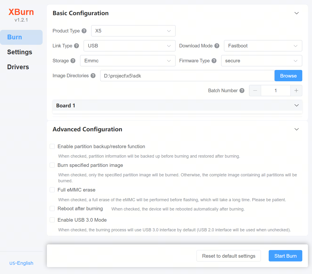
Explanation:
Basic Configuration:
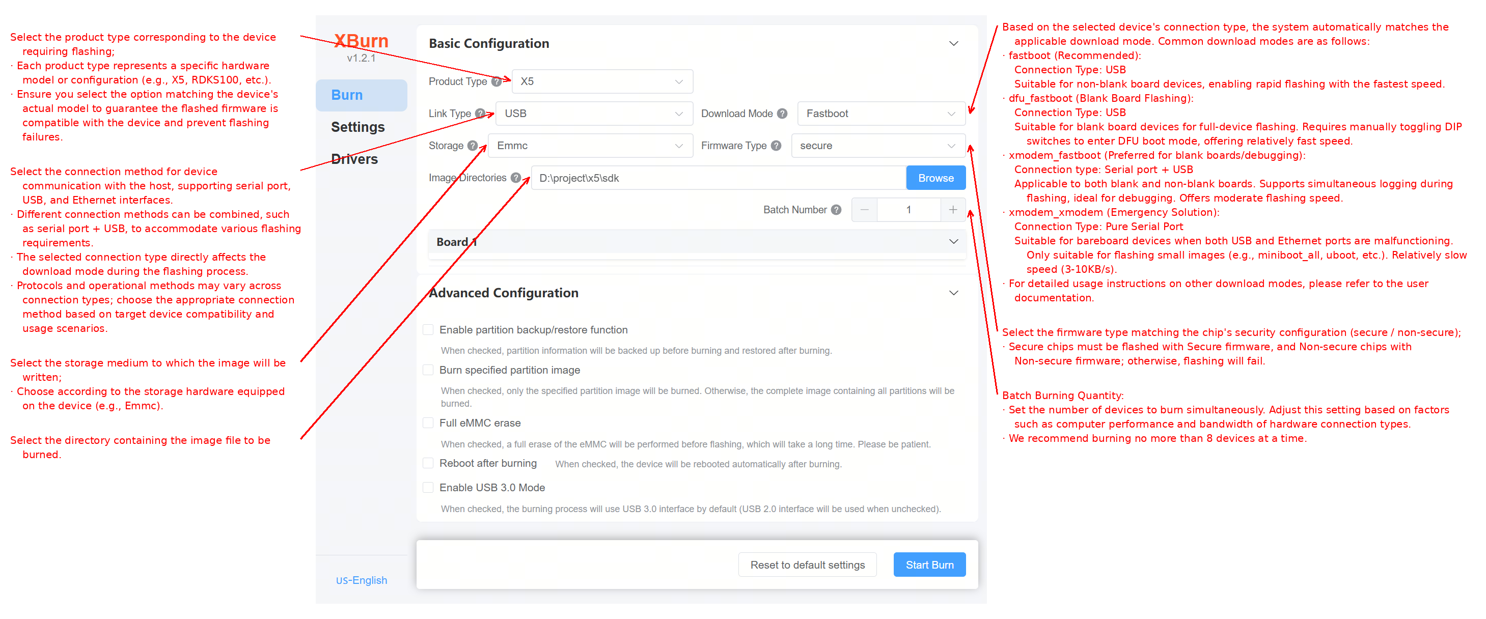
Product Type: Select the corresponding product type for the device you are flashing.
Each product type corresponds to a specific hardware model or configuration (e.g., X5, RDKS100, etc.).
Ensure the selected option matches the actual device model to guarantee firmware compatibility and avoid flashing failure.
Connection Type: Select the communication method between the device and host. Supported options are serial, USB, and Ethernet.
Multiple connection types can be combined (e.g., serial + USB) to meet different flashing needs.
The selected connection type directly affects the download mode used during flashing.
Different connection types may use different protocols and procedures; select the appropriate one based on device compatibility and use case.
Download Mode: Based on the selected connection type, the system automatically matches the applicable download mode. Common modes include:
fastboot (recommended):
Connection Type: USB
Suitable for non-blank devices, enabling fast flashing with the highest speed.
dfu_fastboot (blank board flashing):
Connection Type: USB
Suitable for blank devices, enabling full-system flashing. Requires manual DIP switch configuration to enter DFU boot mode. Fast speed.
xmodem_fastboot (preferred for blank boards/debugging):
Connection Type: Serial + USB
Suitable for both blank and non-blank devices. Supports real-time log viewing during flashing, ideal for debugging. Moderate speed.
xmodem_xmodem (emergency fallback):
Connection Type: Pure serial
Suitable for blank devices when USB and Ethernet are unavailable. Only suitable for small images (e.g., miniboot_all, uboot). Slow speed (3–10 KB/s).
For detailed descriptions of other download modes, refer to the table in the Flashing Methods Overview section.
Image File Directory:
Select the directory containing the image file to be flashed.Batch Flashing Count:
Set the number of devices to flash simultaneously. Adjust based on computer performance and bandwidth of the hardware connection.
It is recommended to flash no more than 8 devices at once.
Advanced Configuration:
Enable Partition Backup/Restore: If checked, partition information will be backed up before flashing and restored afterward.
Flash Specific Partition Image: If checked, only the specified partition image will be flashed; otherwise, a full image containing all partitions will be written.
Erase eMMC Entirely: If checked, the eMMC will be fully erased before flashing, which takes longer—please wait patiently.
Auto-reboot After Flashing: If checked, the device will automatically reboot upon completion.
Enable USB 3.0 Mode: If checked, USB 3.0 will be used; otherwise, USB 2.0 is used by default.
For detailed usage, refer to the Advanced Configuration section.
Operation Buttons:
Restore Default Settings: Reset to default configuration.
Start Upgrade: Begin the flashing process.
Settings Interface
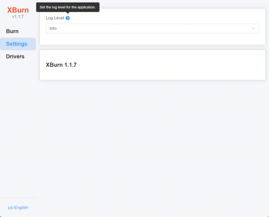
This interface is used to set the log level and control log output verbosity.
Log Level: Choose the log output level (e.g., Info, Debug).
Driver Interface
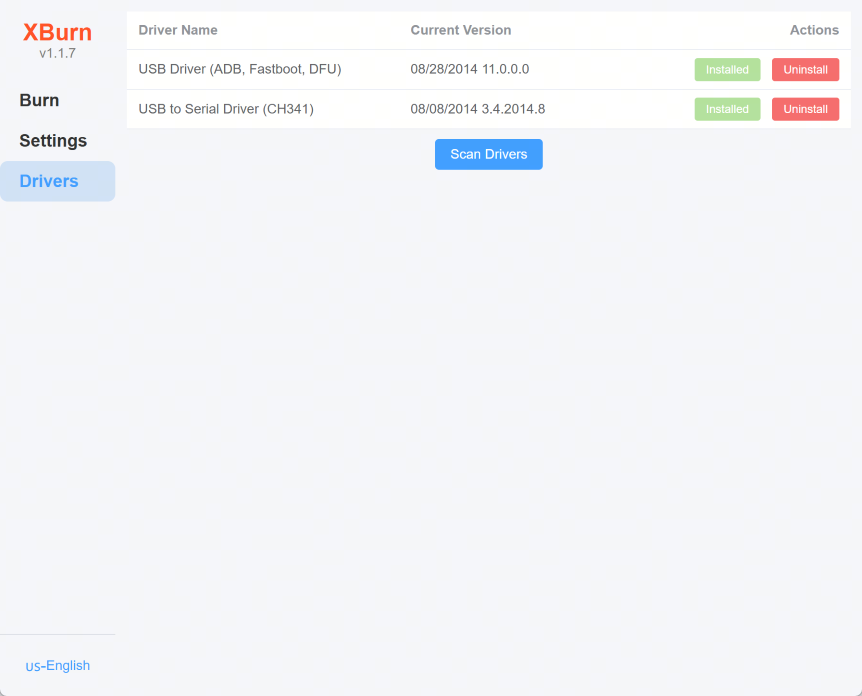
This interface is used to view and manage driver status.
Driver Name: Lists installed drivers (e.g., USB Driver (ADB, Fastboot, DFU), USB to Serial Driver (CH341)).
Current Version: Displays the current driver version.
Actions: Buttons to install or uninstall drivers.
Scan Drivers: Button to detect and install new drivers.
2.5.3.2. Flashing Methods Overview
The XBurn-gui tool supports the following flashing methods:
| Connection Type | Download Mode | Wiring Method | ||
|---|---|---|---|---|
| USB | DFU+Fastboot | Single USB cable | 1. Set the board to DFU boot mode (Set DIP switch D5 to 0, D[2:0] to 010) to download BL2 and BL3x and boot into U-Boot command mode.2. Run fastboot 0 in U-Boot to enter Fastboot mode.3. Use Fastboot over USB to flash the full image. 4. After flashing, restore DIP switches to normal boot mode (e.g., eMMC boot: Set D[5][2:0] to 1001). |
· Supports flashing on blank boards · Must click Start Upgrade within one minute of power-on, otherwise DFU timeout will cause failure |
| USB | Fastboot | Single USB cable | 1. On non-blank boards, ensure the device can enter U-Boot command mode and run fastboot 0:a. If already in Fastboot mode, flash directly. b. Otherwise, if ADB is connected ( adb devices), use adb shell to enter the board terminal, then run reboot -m usb2 -f to enter fastboot mode.2. Use Fastboot over USB to flash the full image. |
· Only supports non-blank boards |
| Serial+USB | Fastboot | Serial + USB cables | 1. On non-blank boards, use serial to enter U-Boot command mode, run fastboot 0 to enter Fastboot mode.2. Use Fastboot over USB to flash the full image. |
· Only supports non-blank boards |
| Serial+USB | Xmodem+fastboot | Serial + USB cables | 1. Use Xmodem over serial to download BL2 and BL3x, boot into U-Boot command mode.2. Run fastboot 0 in U-Boot to enter Fastboot mode.3. Use Fastboot over USB to flash the full image. |
· Supports blank boards · Recommended to set serial baud rate to 921600 (DIP switch D4 set to 1) |
| Serial+USB | Xmodem+DFU | Serial + USB cables | 1. Use Xmodem over serial to download BL2 and BL3x, boot into U-Boot command mode.2. Run dfu 0 in U-Boot to enter DFU mode.3. Use DFU over USB to flash the full image. |
· Supports blank boards · Recommended to set serial baud rate to 921600 (DIP switch D4 set to 1) |
| Serial+USB | DFU | Serial + USB cables | 1. On non-blank boards, use serial to enter U-Boot command mode and run dfu 0 to enter DFU mode.2. Use DFU over USB to flash the full image. |
· Only supports non-blank boards |
| Serial+Ethernet | xmodem_fastboot | Serial + Ethernet cable | 1. Use Xmodem over serial to download BL2 and BL3x, boot into U-Boot command mode.2. Run fastboot udp 0 in U-Boot to start Fastboot UDP service.3. Use host-side fastboot in UDP mode to flash the full image. |
· Supports blank boards · Recommended to set serial baud rate to 921600 (DIP switch D4 set to 1) |
| Serial+Ethernet | fastboot | Serial + Ethernet cable | 1. On non-blank boards, use serial to enter U-Boot command mode and run fastboot udp 0 to start Fastboot UDP service.2. Use host-side fastboot in UDP mode to flash the full image. |
· Only supports non-blank boards |
| Serial | xmodem_xmodem | Single serial cable | 1. Use Xmodem over serial to download BL2 and BL3x, boot into U-Boot command mode.2. Continue using serial protocol (e.g., loady, loadx) in U-Boot to download and flash the image. |
· Supports blank boards · Only recommended for small images · Recommended to set serial baud rate to 921600 (DIP switch D4 set to 1) |
| Serial | xmodem | Single serial cable | 1. On non-blank boards, use serial to enter U-Boot command mode and use serial protocol (e.g., loady, loadx) to download and flash the image.2. All operations are performed over serial. |
· Only supports non-blank boards · Only recommended for small images · Recommended to set serial baud rate to 921600 (DIP switch D4 set to 1) |
Note: For all download modes using the Xmodem protocol, it is recommended to set the serial baud rate to 921600 bps (set DIP switch D4 to 1) to improve flashing speed.
2.5.3.3. Flashing Tool Installation and Startup Guide
Installing and Launching XBurn on Windows
Double-click the installer xburn-gui_X.X.X_x64-setup.exe (the actual version number of the installation package shall prevail) to begin installation. Follow these steps:
Click
Next: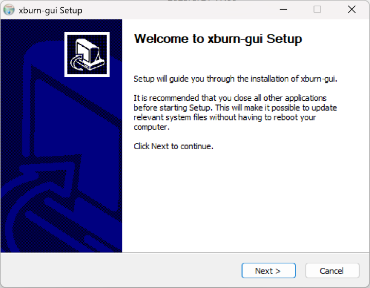
Select
Add/Reinstall components, then clickNext: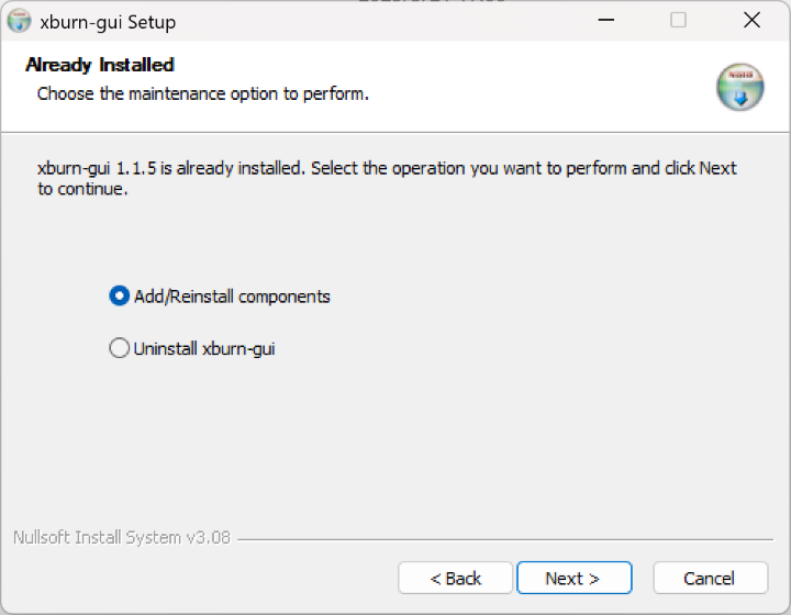
Click
Browseto select the installation path: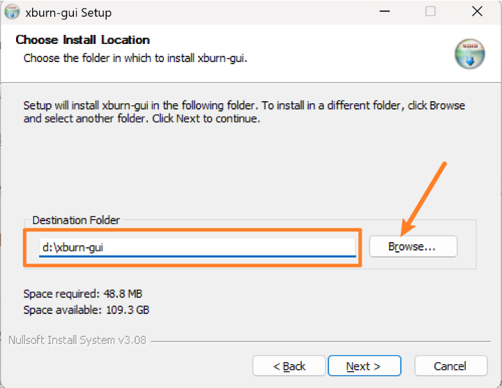
Tip: It is recommended to install the software in the root directory of a hard drive (e.g., D:\xburn-gui) for easier log file access.
Click
Install: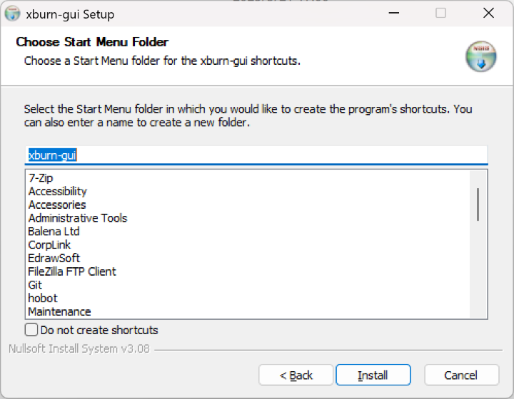
Wait for the progress bar to complete. When
Setup was completed successfully.appears, clickNext: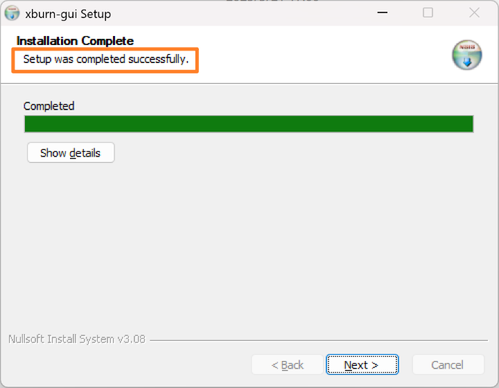
Check
Run xburn-guiandCreate desktop shortcut, then clickFinish: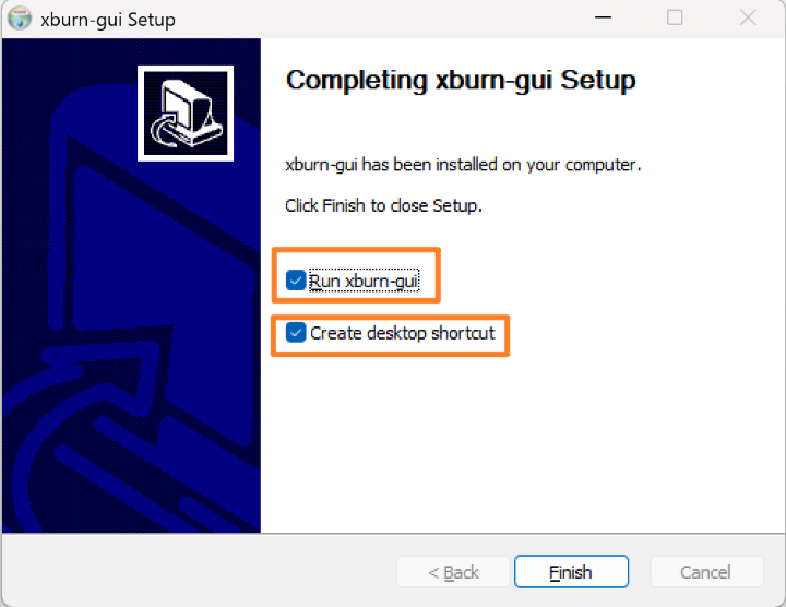
After installation, the XBurn-gui interface will automatically open:
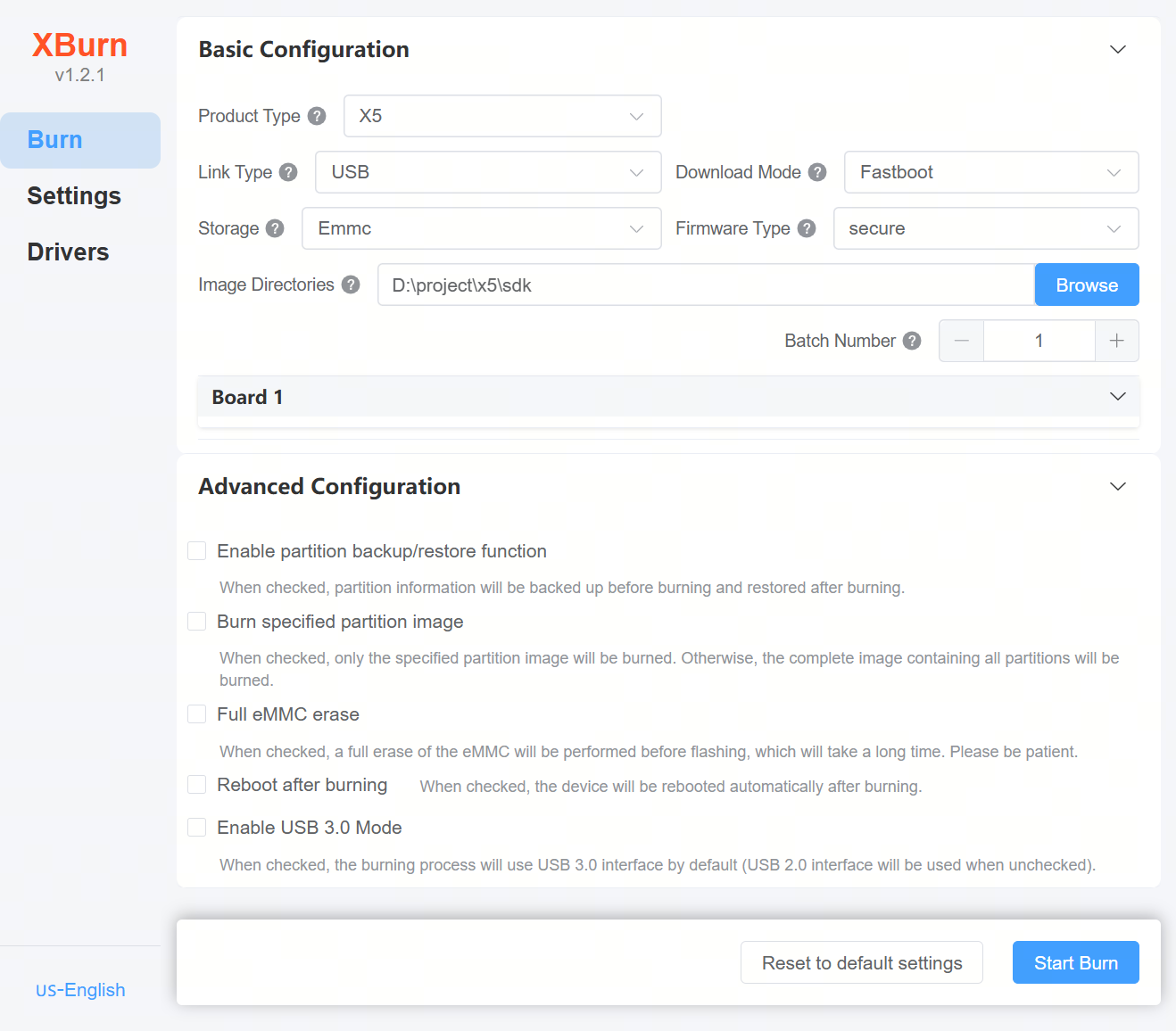
Subsequently, launch the software by double-clicking the
XBurn.exeicon on the desktop.
Installing and Launching XBurn on Ubuntu
Run the command sudo dpkg -i xburn-gui_X.X.X_amd64.deb (the actual version number of the installation package shall prevail) in the package directory to install. Example:
(base) hobot@hobot-ThinkPad-T14-Gen-1:~/tools$  sudo dpkg -i xburn-gui_1.1.7_amd64.deb
[sudo] hobot 的密码:
(Reading database... The system currently has a total of 567832 files and directories installed.)
Prepare to unzip xburn-gui_1.1.7_amd64.deb...
Unpacking xburn-gui (1.1.7) and overwriting (1.1.5)...
Udev rules removed
Setting up xburn-gui (1.1.7)...
Processing triggers for bamfdaemon (0.5.6+22.04.20220217-0ubuntu1) ...
Rebuilding /usr/share/applications/bamf-2.index...
Processing triggers for mailcap (3.70+nmu1ubuntu1) ...
Processing triggers for gnome-menus (3.36.0-1ubuntu3) ...
Processing triggers for desktop-file-utils (0.26-1ubuntu3) ...
Processing triggers for hicolor-icon-theme (0.17-2) ...
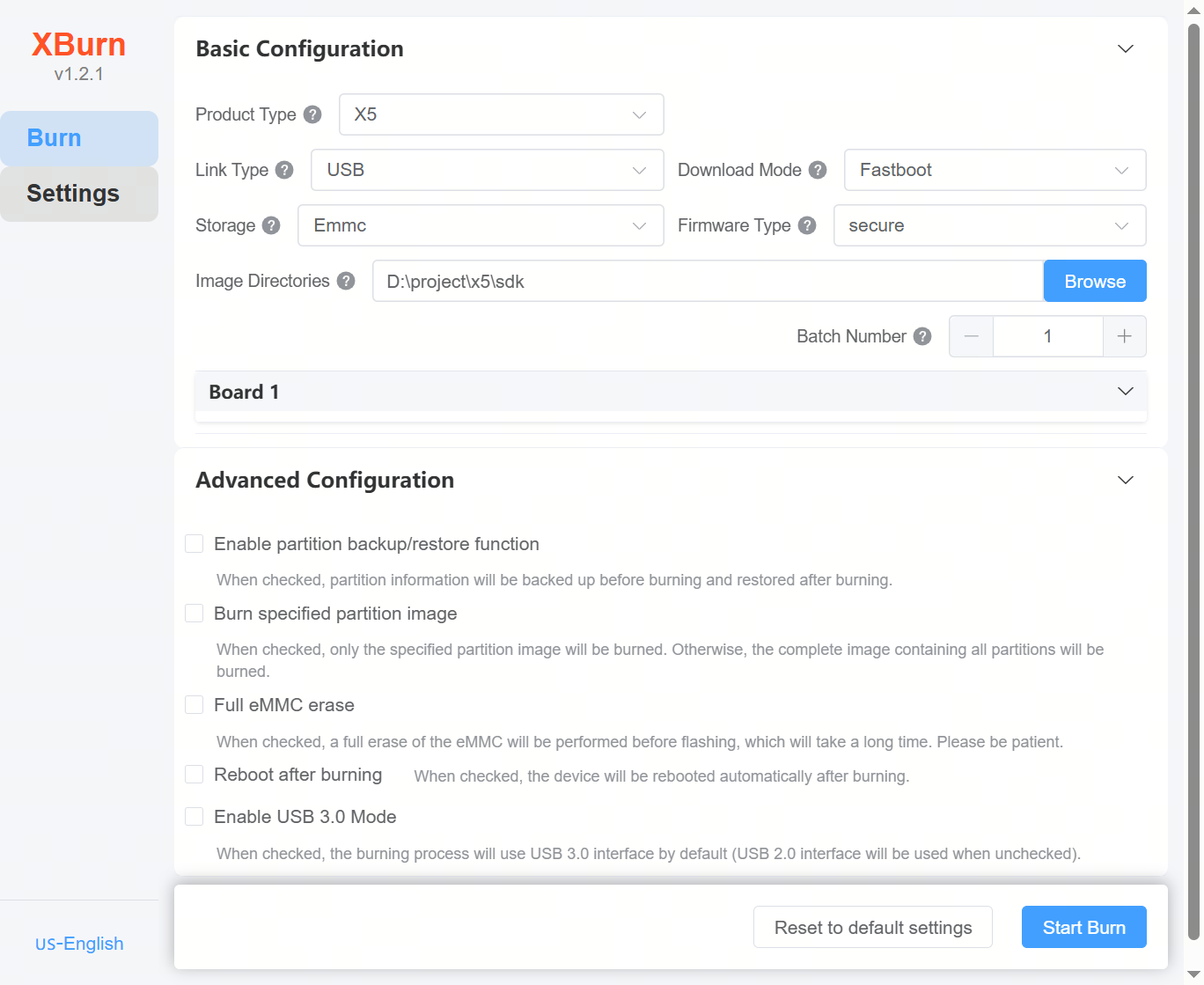
Then run sudo xburn-gui or click the xburn-gui icon in the application menu (password prompt will appear). Enter the password to open the flashing tool interface:
Installing and Launching XBurn on macOS
Double-click the installer xburn-gui_X.X.X_universal.dmg (the actual version number of the installation package shall prevail) to begin installation. Follow these steps:
A pop-up will appear. Click and drag the
xburn-guiicon to theApplicationsfolder: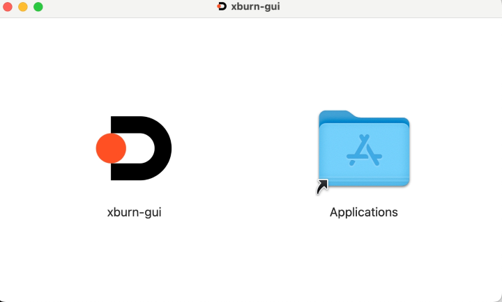
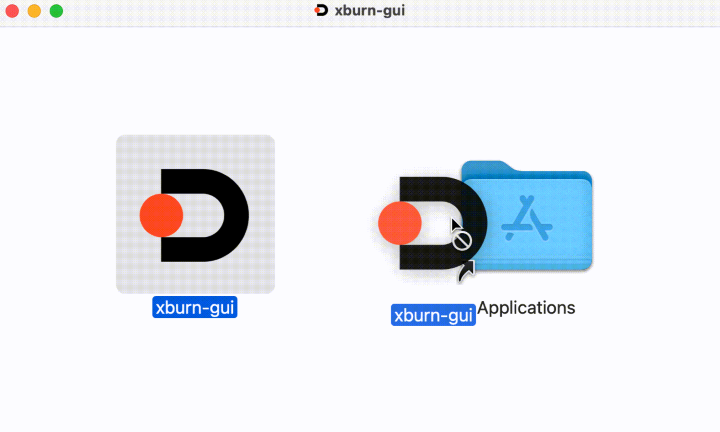
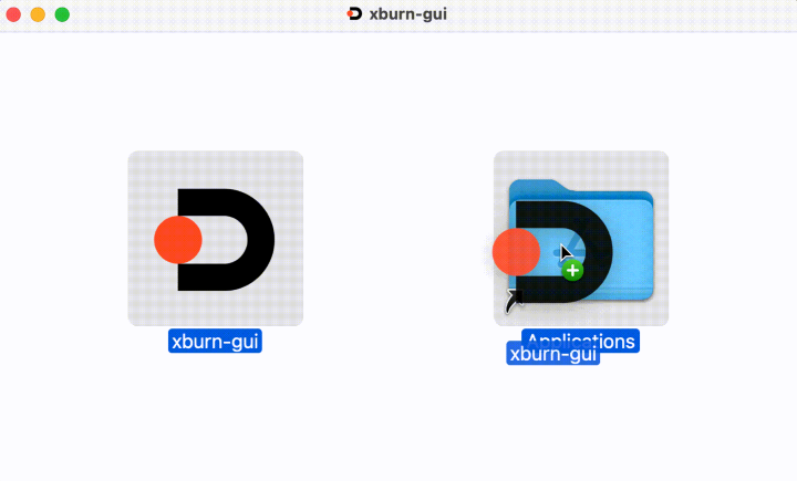
Once installed, double-click the
xburn-guiicon to launch the application: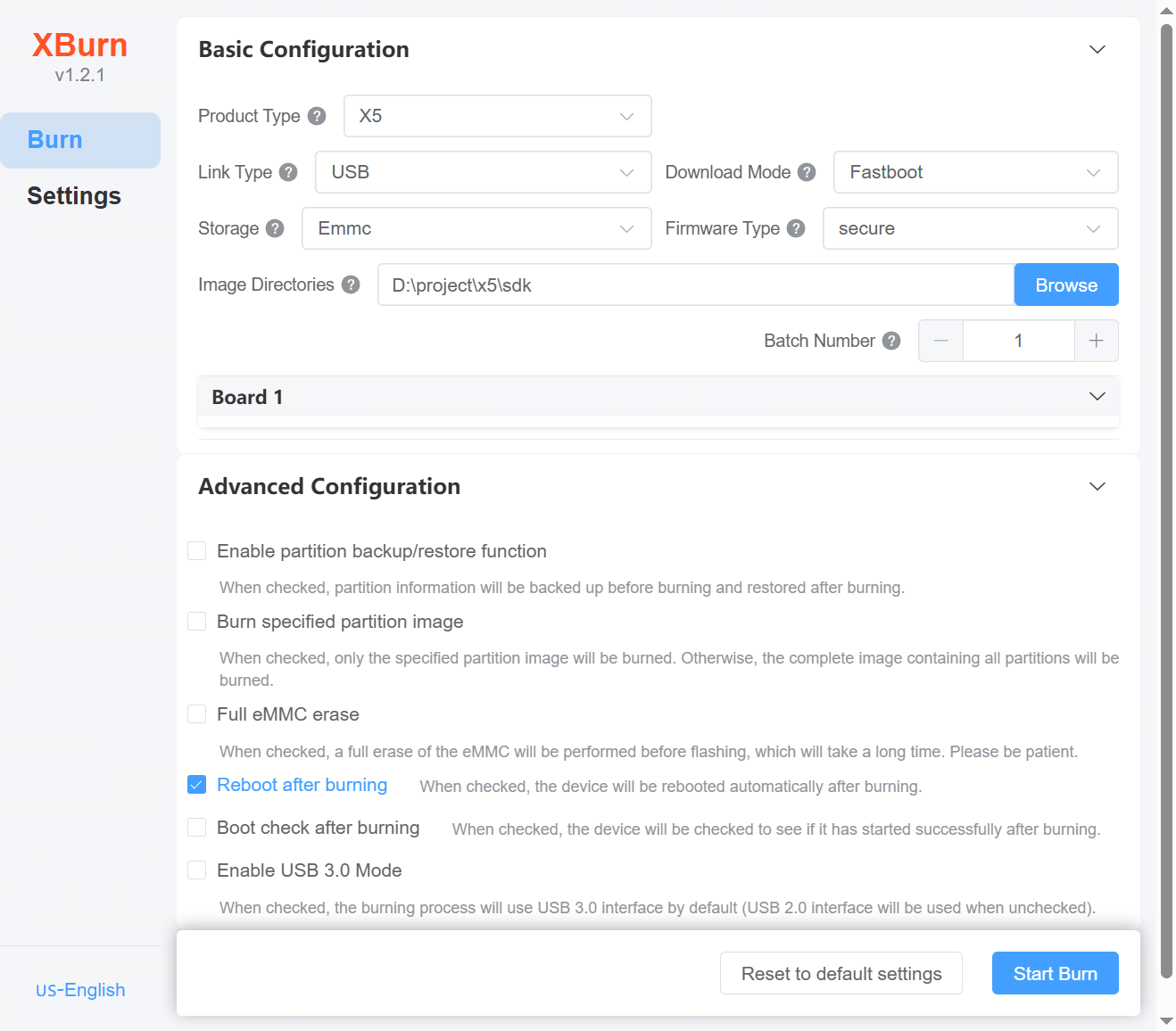
If dependency errors occur during installation, install the required dependencies first.
Common Startup Issues
See FAQ: Common Error Reference Table for common issues and solutions.
2.5.3.4. Flashing Method Selection Guide
For detailed explanations of connection types and download modes, refer to the table in the Flashing Methods Overview section. This section focuses on selecting flashing methods for two scenarios:
The image in the storage medium is empty or corrupted (i.e., the device is bricked);
The image in the storage medium is intact and the device can boot normally.
Selecting Download Mode When Image is Empty or Corrupted
When the image is empty or corrupted, the board cannot enter U-Boot. Only BL1 is available, so BL2 and BL3X images must be flashed using one of the following methods:
Use DFU download mode:
The hardware must have boot DIP switches configured for USB boot;
The DFU bit (usually D5) in BOOT CONFIG must be grounded (set to 0). If the board has a DIP switch for DFU, set it to 0; otherwise, modify the hardware circuit by removing/installing the DFU resistor;
This option can be used when the image is missing or corrupted.
USB boot mode requires the DIP switches to be set as follows: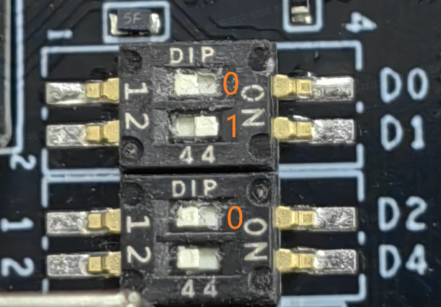
Use Xmodem download mode:
Can be used when the image is missing or corrupted;
In Xmodem mode, for X5 EVB, set DIP switch D4 to 1 (to set serial baud rate to 921600 bps), which significantly increases flashing speed.
Xmodem boot mode requires the DIP switches to be set as follows: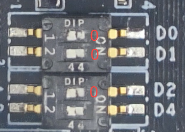
Selecting Download Mode When Image is Normal
When the image is intact, use the Fastboot download mode, which requires the board to enter U-Boot command line:
If the hardware lacks boot DIP switches, ensure a valid bootable image exists in storage—no further action needed;
If DIP switches are present, ensure they are set for normal boot.
The default boot mode is eMMC boot, with DIP switches set as follows:
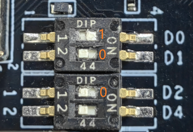
Other boot modes are detailed in the DIP switch truth table in the DIP Switch section.
Note: If the software in storage is missing or corrupted, the X5 chip will automatically switch to USB boot mode.
2.5.3.5. USB Connection Upgrade Procedure
Prerequisites:
Refer to Connecting via USB Port to install USB drivers.
Applicable Scenarios:
USB connection currently supports Fastboot and DFU+Fastboot download modes.
DFU+Fastboot Download Mode
Suitable for boards without a valid image or with a corrupted image, using images from
out/product/uart_usb.Applies to boards with boot DIP switches configured for USB boot mode.
Note: The
Start Upgradebutton must be clicked within one minute of power-on, otherwise DFU timeout will cause upgrade failure.Flashing steps:
Set the board to DFU boot mode (Set DIP switch D5 to 0, D[2:0] to 010) to download BL2 and BL3x and boot into U-Boot command mode.
Run
fastboot 0in U-Boot to enter Fastboot mode.Use Fastboot over USB to flash the full image.
After flashing, restore DIP switches to normal boot mode (e.g., eMMC boot: Set D[5][2:0] to 1001).
Fastboot Download Mode
Only suitable for non-blank boards.
Flashing steps:
On non-blank boards, ensure the device can enter U-Boot command mode and run
fastboot 0:I. If already in Fastboot mode, flash directly.
II. Otherwise, if ADB is connected (
adb devices), useadb shellto enter the board terminal, then runreboot -m usb2 -f:# Windows PowerShell terminal PS C:\Users\xiangqing.shi> adb devices List of devices attached 0x30811a620a494c0f035cefd80000 device PS C:\Users\xiangqing.shi> adb shell sh-5.1# reboot -m usb2 -f
III. Before the operation, if the serial port is connected, the serial log will show:
# board serial terminal
U-Boot 2022.10-g64e3056741 (Jun 18 2025 - 21:44:29 +0800)

Model: Horizon X5
DRAM:  3.9 GiB
console out start addr:0x0000000087ffc000, end addr:0x0000000087ffe000
horizon_lsio_pinctrl lsio_iomuxc@34180000: Initialized D-Robotics pinctrl driver
optee optee: OP-TEE: revision 3.20 (a3b65462)
ADC calibration: -22
ADC trimming: 9
horizon_hsio_pinctrl hsio_iomuxc@35050000: Initialized D-Robotics pinctrl driver
horizon_dsp_pinctrl dsp_iomuxc@31040014: Initialized D-Robotics pinctrl driver
Core:  149 devices, 29 uclasses, devicetree: separate
WDT:   Started watchdog@34250000 with servicing (10s timeout)
stop watchdog
MMC:   sdio-host@35040000: 0, sdio-host@35020000: 1
Loading Environment from MMC... (Tuning Ok!) *** Warning - bad CRC, using default environment

In:    serial@32120000
Out:   serial@32120000
Err:   serial@32120000
Net:
Warning: gmac-tsn@35010000 (eth0) using random MAC address - 92:d9:1f:90:d1:8d
eth0: gmac-tsn@35010000
boot action: FASTBOOT USB2.0
select emmc(0) as flash medium
do fastboot usb
Use Fastboot over USB to flash the full image.
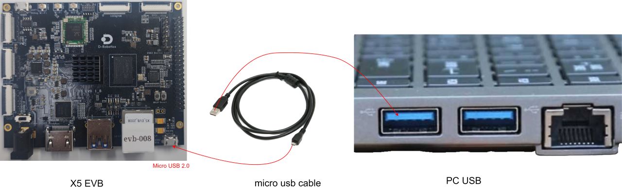
USB Connection Flashing Instructions:
Using DFU+Fastboot mode as an example, the following explains how to use the XBurn-gui tool.
Before flashing, configure the boot mode to USB (set DIP switch D5 to 0, D[2:0] to 010; if no DIP switch, temporarily modify the hardware). If the serial port is connected, the serial terminal will show logs like:
SNOTICE:  Welcome to Horizon X5 ASIC BOOTROM - V4.1
NOTICE:                 OTP config:
NOTICE:                         otp exist: true
NOTICE:                         test region size: 304
NOTICE:                         secure region size: 120
NOTICE:                         none secure region size: 56
NOTICE:   Enable MMU
NOTICE:  Booting Trusted Firmware
NOTICE:  BL1: v2.8(release):
NOTICE:  BL1: Built : 17:42:12, Oct 19 2023
NOTICE:  Enter USB2 Mode......
NOTICE:  Currtenly use dfu-util to download file
NOTICE:  Download file via USB
NOTICE:  DFU Start...
XBurn-gui tool configuration:
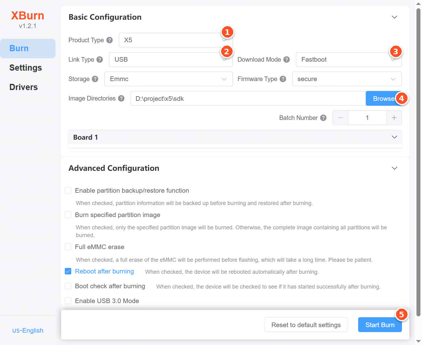
Step 1:
Select product type. In the Product Type dropdown, select X5.
Step 2:
Select connection type. In the Connection Type dropdown, select USB.
Step 3:
Select download mode. In the Download Mode dropdown, select DFU+Fastboot.
Step 4:
Select the image directory. Click Browse and choose the image folder, typically the out/product directory generated after compilation, e.g., S:\home\sxq\projects\sdk_x5_main\out\product.
Step 5:
Power on the board, then click Start Upgrade. The tool will begin flashing. When the progress bar reaches 100%, the upgrade is successful.
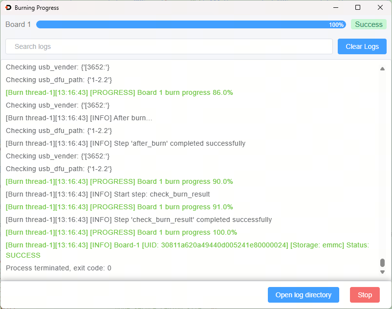
Step 6:
After flashing, restore DIP switches to normal boot mode (e.g., eMMC boot: Set D[5][2:0] to 1001).
Note: The Start Upgrade button must be clicked within one minute of powering on the board. Otherwise, the board will exit DFU mode due to timeout, entering Xmodem file transfer waiting state. The flashing tool will usually report an error like:
[Burn thread-1][20:09:55] [WARNING] Minimum dfu device detect timeout is 30s!
[Burn thread-1][20:09:55] [INFO] Executing 'tools/windows/dfu-util.exe -l', waiting for 60 seconds for execution to finish...
dfu-util 0.11
......
Determining device status...
error get_status: LIBUSB_ERROR_PIPE
[Burn thread-1][20:09:58] [ERROR] DFU download 'S:\home\sxq\projects\sdk_x5_main\out\product\uart_usb/bl2_usb2_ddr.bin' failed
......
[Burn thread-1][20:09:58] [ERROR] Step 'dfu_boot' failed
[Burn thread-1][20:09:58] [ERROR] Board-1, burn failed
[Burn thread-1][20:09:58] [ERROR] Board-1 [UID: 1-2.2] [Storage: emmc] Status: FAILED
Process terminated, exit code: 0
If the serial port is connected during USB upgrade, the serial terminal will show:
NOTICE:  Welcome to Horizon X5 ASIC BOOTROM - V4.1
NOTICE:                 OTP config:
NOTICE:                         otp exist: true
NOTICE:                         test region size: 304
NOTICE:                         secure region size: 120
NOTICE:                         none secure region size: 56
NOTICE:   Enable MMU
NOTICE:  Booting Trusted Firmware
NOTICE:  BL1: v2.8(release):
NOTICE:  BL1: Built : 17:42:12, Oct 19 2023
NOTICE:  Enter USB2 Mode......
NOTICE:  Currtenly use dfu-util to download file
NOTICE:  Download file via USB
NOTICE:  DFU Start...
NOTICE:  USB DFU function timeout and need switch to xmodem download
NOTICE:   dfu-util timeout, forcily switch xmodem download......
## Ready for (xmodem) download to 0x1ff00000
CCCCCCCCCCCCCCCCCCCCCCCCCCCCCCCCCCCCCCCCCCCCCCCCCCCCCCCCCCCC
If DFU timeout causes failure, power off and restart the board, then retry the upgrade.
2.5.3.6. Serial+USB connection mode upgrade process description
Prerequisite:
Please refer to Connect by serial port to complete the installation of the serial port driver.
Please refer to Connect by USB to complete the USB driver installation.
Scope of application:
When using the Serial+USB connection method, four download modes are supported: Fastboot, Xmodem+fastboot, Xmodem+DFU, and DFU. Detailed descriptions of these four download methods can be found in the table within the Flashing Methods Overview section.
Need to explain:
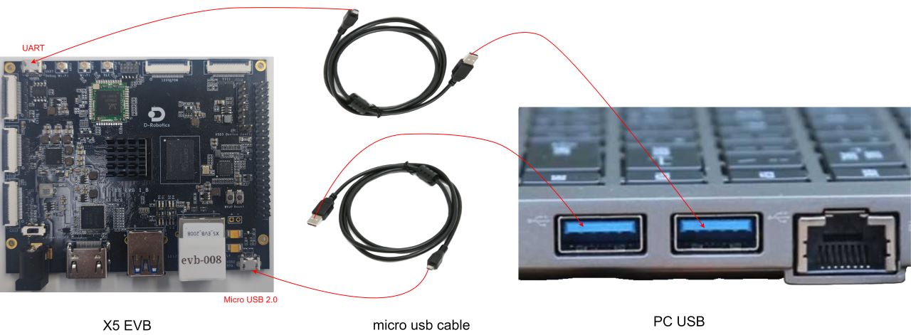
This connection type is suitable for scenarios where the serial port and USB interface can be connected at the same time;
In this connection type, you can choose the Xmodem+fastboot and Xmodem+DFU download modes. The Xmodem protocol is used for burning in scenarios where there is no available image on the development board or the image is damaged. In this case, you need to use the image BL2 and BL3X in
out/product/uart_usb. In this case, it is recommended to set the serial port baud rate to 921600 (Dial switch D4 is set to 1).
The following uses Fastboot download mode as an example for explanation.
The XBurn-gui burning tool interface configuration is as follows:
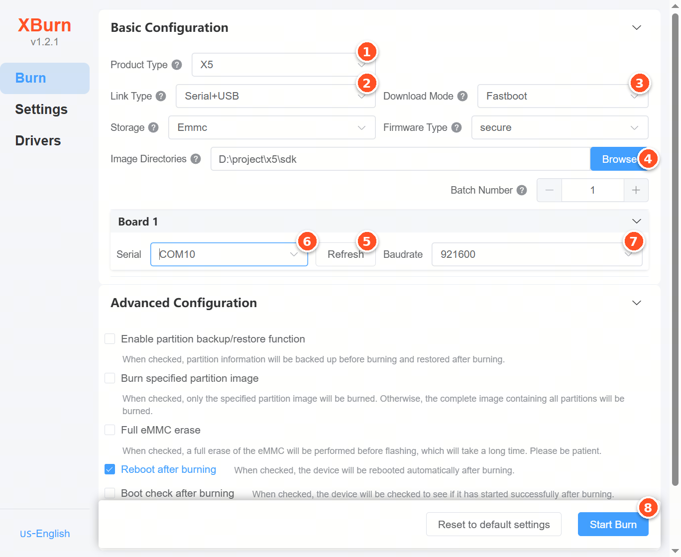
The following is the detailed description of the burning process:
Step 1:
Select the product type. Click the Product Type dropdown list and select model X5.
Step 2:
Select the connection type. Click the Connection Type dropdown list and select Serial+USB.
Step 3:
Select the download mode. Click the Download Mode dropdown list and select Fastboot mode.
Step 4:
Select the directory of the image to be flashed. Click Browse, then select the directory containing the image files, typically the out/product directory generated after system compilation, such as S:\home\sxq\projects\sdk_x5_main\out\product.
Step 5:
Click the Refresh button to ensure the software recognizes the correct serial port.
Step 6:
Select the serial port. From the Serial Port dropdown, choose the correct COM port, such as COM6.
Step 7:
Set the baud rate. In the Baud Rate field, enter or select the correct baud rate, for example 921600 (recommended).
Step 8:
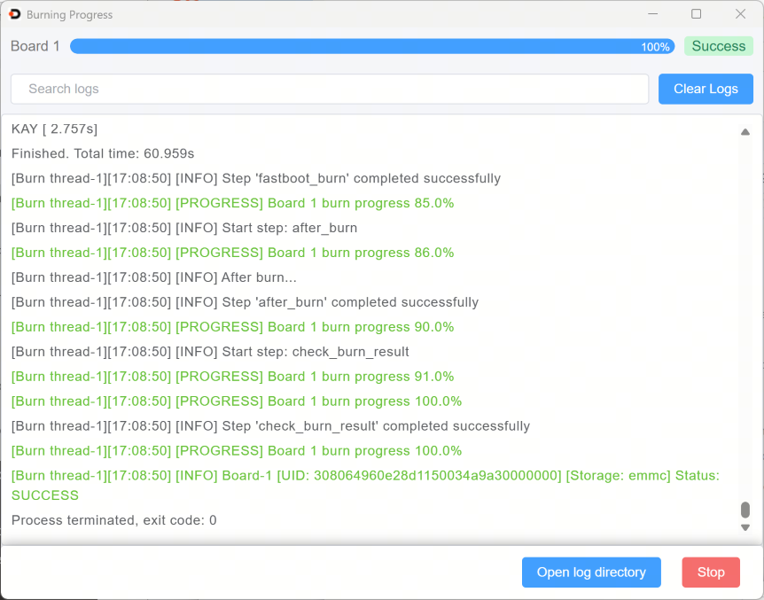
Start flashing. Power on the development board, then click Start Upgrade. The tool will begin flashing. When the progress bar reaches 100%, the upgrade is successful.
2.5.3.7. Serial+Ethernet Connection Upgrade Procedure
Prerequisites:
Please refer to Connect via Serial Port to complete the installation of the serial driver.
Please refer to Connecting via Network Interface to understand how to connect the development board to the PC.
Applicable Scenarios:
The Serial+Ethernet connection supports two download modes: Fastboot over Ethernet and Xmodem+fastboot. For detailed explanations of these download modes, please refer to the table in the Flashing Methods Overview section.
This connection method applies to scenarios where both the serial port and Ethernet port can be connected simultaneously.
This connection method supports the Xmodem+fastboot download mode, which uses the Xmodem protocol for flashing in cases where the development board has no valid image or the image is corrupted. In this case, use the BL2 and BL3X images from
out/product/uart_usb. It is recommended to set the serial baud rate to 921600 (DIP switch D4 set to 1).
The following description uses Fastboot download mode as an example.
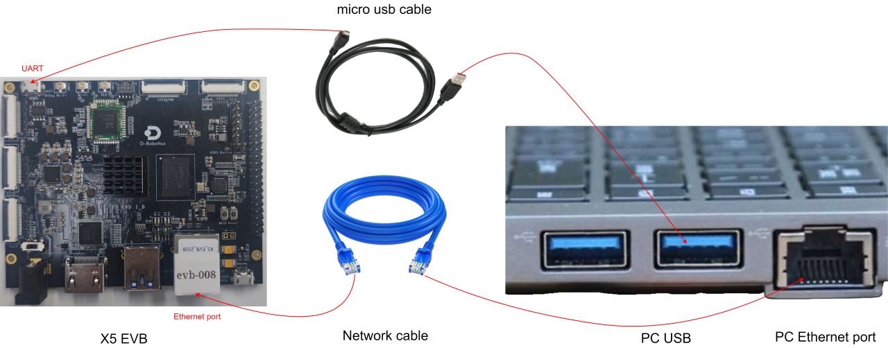
Wiring Diagram:
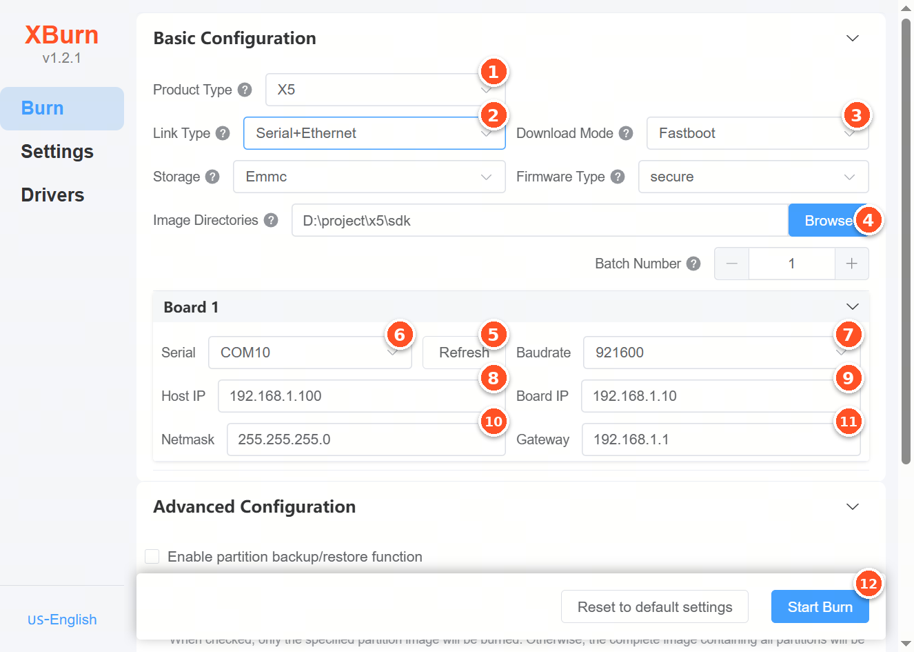
Configuration of the XBurn-gui flashing tool interface:
Below is the detailed description of the flashing process:
Step 1:
Select the product type. From the Product Type dropdown list, select X5.
Step 2:
Select the connection type. From the Connection Type dropdown list, select Serial+Ethernet.
Step 3:
Select the download mode. From the Download Mode dropdown list, select Fastboot.
Step 4:
Select the image directory. Click the Browse button and select the directory containing the image files, for example S:\home\sxq\projects\sdk_x5_main\out\product.
Step 5:
Click the Refresh button to ensure the software recognizes the correct serial port.
Step 6:
Select the serial port. From the Serial Port dropdown list, select the currently used COM port, such as COM6.
Step 7:
Set the baud rate. From the Baud Rate dropdown list, select the current serial port baud rate, such as 921600.
Step 8:
Set the host IP. In the Host IP input field, enter the static IP address of the PC’s network interface, such as 192.168.1.101.
Step 9:
Set the board IP. In the Board IP input field, enter 192.168.1.10 (default IP).
Step 10:
Set the subnet mask. In the Subnet Mask input field, enter 255.255.255.0.
Step 11:
Set the gateway. In the Gateway input field, enter 192.168.1.1.
Step 12:
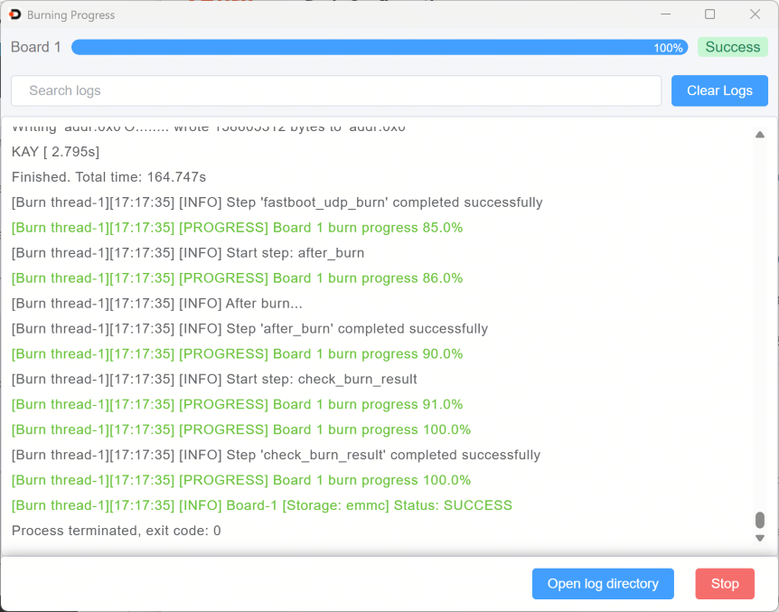
Start flashing. Click the Start Upgrade button to begin the flashing process. When the progress bar reaches 100%, the upgrade is successful.
2.5.3.8. Serial Connection Upgrade Procedure
Prerequisites:
Please refer to Connect via Serial Port to complete the installation of the serial driver.
Applicable Scenarios:
The Serial connection supports two download modes: Xmodem and Xmodem+Xmodem. For detailed explanations of these download modes, please refer to the table in the Flashing Methods Overview section.
This connection method applies to scenarios where only the serial port can be connected.
All supported download modes in this connection use the Xmodem protocol for flashing when the development board has no valid image or the image is corrupted. In this case, use the BL2 and BL3X images from
out/product/uart_usb. It is recommended to set the serial baud rate to 921600 (DIP switch D4 set to 1).This connection method is only recommended for flashing small-sized images, as Xmodem transfer speed is very slow.
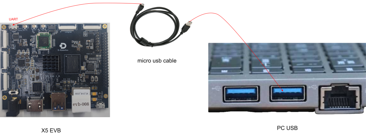
The following description uses Xmodem download mode as an example.
Wiring Diagram:
Configuration of the XBurn-gui flashing tool interface:
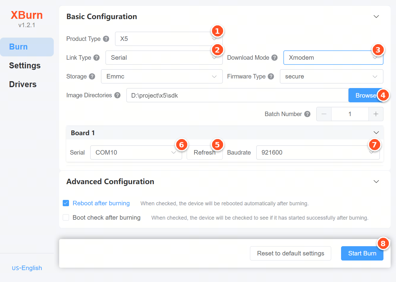
Below is the detailed description of the flashing process:
Step 1:
Select the product type. From the Product Type dropdown list, select X5.
Step 2:
Select the connection type. From the Connection Type dropdown list, select Serial.
Step 3:
Select the download mode. From the Download Mode dropdown list, select Xmodem.
Step 4:
Select the image directory. Click the Browse button and select the directory containing the image files, for example S:\home\sxq\projects\sdk_x5_main\out\product.
Step 5:
Select the serial port. From the Serial Port dropdown list, select COM6.
Step 6:
Click the Refresh button to refresh the serial port list and ensure the correct serial port is selected.
Step 7:
Set the baud rate. In the Baud Rate input field, enter 921600.
Step 8:
Start flashing. Click the Start Upgrade button to begin the flashing process. Xmodem transfer speed is very slow; please be patient.
2.5.3.9. Advanced Configuration
Auto-reboot after flashing
When the option Auto-reboot after flashing is checked, the development board will automatically reboot upon completion of the image flashing.
By default, this option is checked. After flashing, the board will reboot automatically. If unchecked, the board remains in the state it was in at the end of the flashing process. For example, if flashing was done via fastboot and auto-reboot is unchecked, the board will remain in fastboot mode after completion.
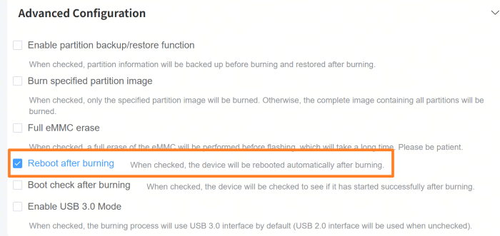
When checked, an additional option Check if device rebooted successfully becomes available for selection.
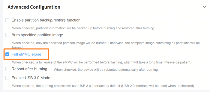
Full eMMC Erase
When Full eMMC Erase is checked, if the main storage medium on the development board is eMMC, the entire eMMC will be erased before flashing the image.
Full eMMC erase takes a long time; please be patient. A full erase of a 16GB eMMC takes 3–5 minutes.
If
Burn specified partition imagemode is selected, checkingFull eMMC Erasewill have no effect.
Enable Partition Backup/Restore Function
Overview
The XBurn-gui flashing tool supports partition backup and restore functionality. You can specify a partition to back up, and after flashing a new image, the backed-up partition will be rewritten to the development board, ensuring that the data in that partition remains unchanged despite the new image flashing.
Applicable Scenarios
The development board’s storage medium must already have partitions.
Usage Method
By default, no partition backup is performed during flashing.
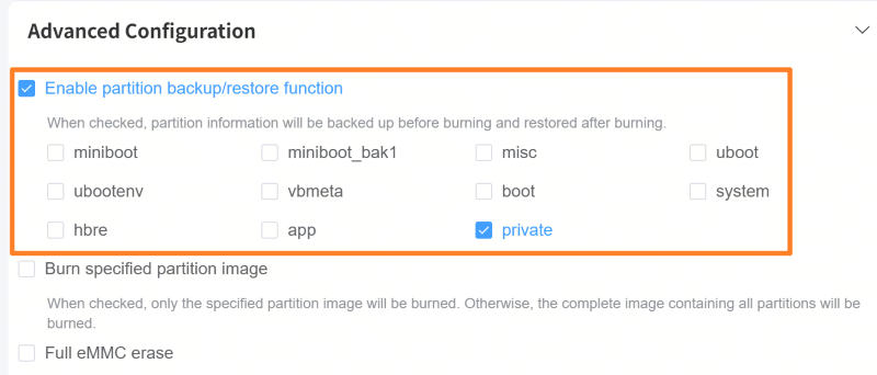
Check the
Enable Partition Backup/Restore Functionoption and select the partition(s) to back up. During flashing, the selected partitions will be backed up.
The flashing steps are otherwise identical to those described for the previous connection methods, except for the additional step of checking the Enable Partition Backup/Restore Function option.
Note: After flashing is complete, reboot the development board and verify that the partition backup was successful.
Burn Specified Partition Image
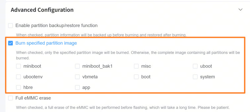
Burn Specified Partition Image: This option supports flashing only one or more specific partitions from the image, leaving other partitions unaffected. It is suitable for the following scenarios:
Only updating a specific component in the system (e.g., miniboot, uboot, system, app partitions)
Performing a system upgrade without affecting user data partitions
After selecting this mode, you must manually choose the target partition(s) to flash.
2.5.4. Command-line Tool Introduction (Factory Version)
2.5.4.1. Overview
The command-line tool is the core execution module of the GUI tool, capable of independent operation with identical functionality. Both tools share the same underlying principles. Users can choose the tool that best suits their needs.
Image preparation, environment configuration, and supported flashing methods are consistent with the GUI tool and will not be elaborated here.
2.5.4.2. Command-line Environment Configuration
On Windows, add the installation directory of the xburn-gui flashing tool to the system environment variables to enable command-line flashing operations. For example:
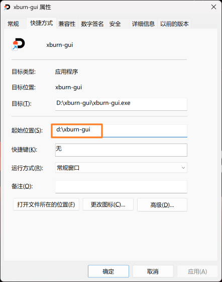
Add the above path D:\xburn-gui to the system environment variables as follows:
Press Win + R to open the Run dialog.
Type
sysdm.cpland press Enter.In the
System Propertieswindow, go to theAdvancedtab and clickEnvironment Variablesat the bottom right.In the
Environment Variableswindow, select thePathvariable and clickEdit.In the
Edit Environment Variablewindow, clickNewand paste the installation path of the xburn-gui flashing tool.Click
OK.
On Ubuntu, the xburn command is automatically integrated into /usr/bin/ after installation and can be used directly.
2.5.4.3. Command-line Usage
On the PC, open the command-line interface of the corresponding system and execute sudo xburn (on Ubuntu and macOS terminals) or xburn (on Windows PowerShell) to start flashing. Run xburn --help to view the complete usage:
$ xburn --help
usage: xburn [-h] [-s {product,serial,dfu,adb}] [-c CONFIG] [-v, --version] [-V {debug,info,warning,error,critical}] [-p PRODUCT_TYPE] [-l {usb,ethernet,serial,serial_usb,serial_ethernet}] [-d {fastboot,dfu,dfu_fastboot,xmodem,xmodem_fastboot,xmodem_dfu,xmodem_xmodem}] [-i IMG_FILES] [--erase_scrub]
             [--security {secure,secure_ohp,nosecure}] [--boot_check] [--batch_num BATCH_NUM] [--host_ip HOST_IP] [--board_ip BOARD_IP] [--netmask NETMASK] [--gateway GATEWAY] [--ipv6] [--usb_port {usb2.0,usb3.0}] [--serial SERIAL] [--baudrate BAUDRATE] [--mcu_serial MCU_SERIAL]
             [--hsm_serial HSM_SERIAL] [--erase_part ERASE_PART] [--select_part SELECT_PART] [--backup_part BACKUP_PART] [--reboot]

Command-line interface for the application.

optional arguments:
  -h, --help            show this help message and exit

Status query and other configurations::
  -s {product,serial,dfu,adb}, --scan {product,serial,dfu,adb}
                        Scan serial, dfu, adb and supported product lists.
  -c CONFIG, --config CONFIG
                        Path to the xburn config file.
  -v, --version         Display compiler version information.
  -V {debug,info,warning,error,critical}, --log_level {debug,info,warning,error,critical}
                        Set the logging level (default: info).

Burn configuration Arguments::
  -p PRODUCT_TYPE, --product_type PRODUCT_TYPE
                        Specify the product type.
  -l {usb,ethernet,serial,serial_usb,serial_ethernet}, --link_type {usb,ethernet,serial,serial_usb,serial_ethernet}
                        Specify the hardware link type.
  -d {fastboot,dfu,dfu_fastboot,xmodem,xmodem_fastboot,xmodem_dfu,xmodem_xmodem}, --dl_mode {fastboot,dfu,dfu_fastboot,xmodem,xmodem_fastboot,xmodem_dfu,xmodem_xmodem}
                        Specify the download mode.
  -i IMG_FILES, --img_files IMG_FILES
                        Specify img_files (comma separated).
  --erase_scrub         Enable or disable storage erase scrub.
  --security {secure,secure_ohp,nosecure}, --security_type {secure,secure_ohp,nosecure}
                        Specify the security type.
  --boot_check          Enable or disable boot check.
  --batch_num BATCH_NUM
                        Specify the number of boards to burn in batch.
  --host_ip HOST_IP     Specify the network host IP (comma separated).
  --board_ip BOARD_IP   Specify the network board IP (comma separated).
  --netmask NETMASK     Specify the network netmask (comma separated).
  --gateway GATEWAY     Specify the network gateway (comma separated).
  --ipv6                Enable or disable IPv6 network configuration.
  --usb_port {usb2.0,usb3.0}
                        Specify the usb port.
  --serial SERIAL       Specify the serial port.
  --baudrate BAUDRATE   Specify the serial port baud rate.
  --mcu_serial MCU_SERIAL
                        Specify the MCU serial port.
  --hsm_serial HSM_SERIAL
                        Specify the Hardware Security Module serial port.
  --erase_part ERASE_PART
                        Specify partitions to erase (comma separated).
  --select_part SELECT_PART
                        Specify partitions to select (comma separated).
  --backup_part BACKUP_PART
                        Specify partitions to backup (comma separated).
  --reboot              Enable or disable board reboot after burn.
Below is a brief explanation of these parameters.
Status Query and Basic Configuration
| Parameter | Abbreviation | Options | Description | Example | Format Requirements |
|---|---|---|---|---|---|
--scan |
-s |
product, serial, dfu, adb |
Scan devices or product lists | -s serial |
Single selection |
--config |
-c |
File path | Specify config file path | -c XXX |
- |
--version |
-v |
None | Display compiler version | -v |
- |
--log_level |
-V |
debug, info, warning, error, critical |
Set log level (default: info) |
-V debug |
- |
Core Flashing Configuration
| Parameter | Abbreviation | Options | Description | Example | Format Requirements |
|---|---|---|---|---|---|
--product_type |
-p |
Product model (currently only X5, RDKS100) |
Required; specify hardware model | -p X5 |
Must match device |
--link_type |
-l |
usb, ethernet, serial, serial_usb, serial_ethernet |
Physical connection type | -l serial_usb |
- |
--dl_mode |
-d |
fastboot,dfu,dfu_fastboot,xmodem,xmodem_fastboot,xmodem_dfu,xmodem_xmodem |
Flashing protocol combination (depends on connection type) | -d xmodem_fastboot |
- |
--img_files |
-i |
Image path | Specify image(s) to flash | -i boot.img,system.img |
Comma-separated paths for multi-board parallel flashing |
--batch_num |
- | Integer (recommended ≤8) | Number of devices to flash in parallel | --batch_num 4 |
- |
--reboot |
- | - | Automatically reboot device after flashing | --reboot |
- |
Protocol Selection Logic:
Empty board state → Prefer
dfuorxmodem_xmodem(serial emergency)Non-empty board → Prefer
fastboot(USB high-speed)Debugging needs →
xmodem_fastboot(serial logs + USB flashing)
Partition Operations and Security Control
| Parameter | Abbreviation | Options | Description | Example | Format Requirements |
|---|---|---|---|---|---|
--erase_part |
- | List of partition names | Erase specified partitions | --erase_part cache,userdata |
Comma-separated partition names |
--select_part |
- | List of partition names | Flash only selected partitions | --select_part boot |
Comma-separated partition names |
--backup_part |
- | List of partition names | Backup partitions before flashing | --backup_part recovery |
Comma-separated partition names |
--erase_scrub |
- | Boolean | Enable deep storage erase (enhanced security) | --erase_scrub |
- |
--security_type |
- | secure, secure_ohp, nosecure |
Device security mode (affects boot verification) | --security secure |
- |
--boot_check |
- | Boolean | Verify boot integrity after flashing | --boot_check |
- |
Network Configuration
| Parameter | Abbreviation | Options | Description | Example | Format Requirements |
|---|---|---|---|---|---|
--host_ip |
- | IPv4/IPv6 address | Host IP address | --host_ip 192.168.1.100 |
Comma-separated IPs (for multiple devices) |
--board_ip |
- | IPv4/IPv6 address | Board IP address | --board_ip 192.168.1.101,192.168.1.102 |
Comma-separated IPs (for multiple devices) |
--netmask |
- | Subnet mask | Network subnet mask | --netmask 255.255.255.0 |
- |
--gateway |
- | IPv4/IPv6 address | Gateway address | --gateway 192.168.1.1 |
- |
--ipv6 |
- | Boolean | Enable IPv6 network config | --ipv6 |
- |
Interface Configuration
| Parameter | Abbreviation | Options | Description | Example | Format Requirements |
|---|---|---|---|---|---|
--usb_port |
- | usb2.0, usb3.0 |
USB interface speed selection | --usb_port usb3.0 |
- |
--serial |
- | Serial device path | Specify serial port path | --serial /dev/ttyUSB0, --serial COM10 |
- |
--baudrate |
- | Currently only 115200 and 921600 |
Set serial baud rate | --baudrate 115200 |
- |
--mcu_serial |
- | Serial device path | MCU debug serial (for special devices) | --mcu_serial /dev/ttyACM1 |
- |
--hsm_serial |
- | Serial device path | HSM security module serial | --hsm_serial /dev/ttyHS0 |
- |
Usage Examples
Single-device flashing (Serial + USB Fastboot)
xburn -V info -p X5 -l serial_usb -d fastboot -i S:\home\sxq\projects\sdk_x5_main\out\product --batch_num 1 --baudrate 921600 --serial COM6 --reboot
Empty board debugging (Serial + USB xmodem_fastboot)
xburn -V info -p X5 -l serial_usb -d xmodem_fastboot -i S:\home\sxq\projects\sdk_x5_main\out\product --batch_num 1 --baudrate 921600 --serial COM6 --reboot
Successful execution log:
Finished. Total time: 31.990s
[Burn thread-1][18:44:37] [INFO] Step 'fastboot_burn' completed successfully

[Burn thread-1][18:44:37] [PROGRESS] Board 1 burn progress 85.0%
[Burn thread-1][18:44:37] [INFO] Start step: after_burn

[Burn thread-1][18:44:37] [PROGRESS] Board 1 burn progress 86.0%
[Burn thread-1][18:44:37] [INFO] After burn...
[Burn thread-1][18:44:37] [INFO] Step 'after_burn' completed successfully

[Burn thread-1][18:44:37] [PROGRESS] Board 1 burn progress 90.0%
[Burn thread-1][18:44:37] [INFO] Start step: check_burn_result

[Burn thread-1][18:44:37] [PROGRESS] Board 1 burn progress 91.0%
[Burn thread-1][18:44:37] [ERROR] Write failed: Write timeout
[Burn thread-1][18:44:37] [INFO] Reconnected successfully

[Burn thread-1][18:44:37] [PROGRESS] Board 1 burn progress 100.0%
[Burn thread-1][18:44:37] [INFO] Step 'check_burn_result' completed successfully

[Burn thread-1][18:44:37] [PROGRESS] Board 1 burn progress 100.0%
[Burn thread-1][18:44:37] [INFO] Board-1 [UID: 308064960e30c82402062d570000024] [Storage: emmc] Status:  SUCCESS
Scan available serial ports
xburn -s serial
Command execution log:
PS C:\Users\xiangqing.shi> xburn -s serial
Scanning for serial information...
Detected serial devices:
Device: COM6, Description: USB-SERIAL CH340 (COM6), HWID: USB VID:PID=1A86:7523 SER= LOCATION=1-2.3
2.5.5. Manual Flashing Tool Introduction
2.5.5.1. Flashing Images Using Fastboot Commands
Prerequisites:
Please refer to Connect via Serial Port to complete the installation of the serial driver. In Device Manager on Windows, you should see the corresponding COM port; in the
/devdirectory on Ubuntu, you can find the corresponding tty serial device.Please refer to Connecting via USB Port to complete the installation of the USB driver. On Windows, it usually appears as
Android Bootloader Interfacein Device Manager.
Applicable Scenarios:
This flashing method applies to development boards that already have a valid image and can boot normally. It does not apply to boards with no image or corrupted images.
Tips:
The graphical
xburn-guipackage includes the Fastboot tool. The Windows version is located in thexburn-gui\tools\windowsdirectory under the installation path.On Windows, you can add the
fastboottool path to the environment variables.
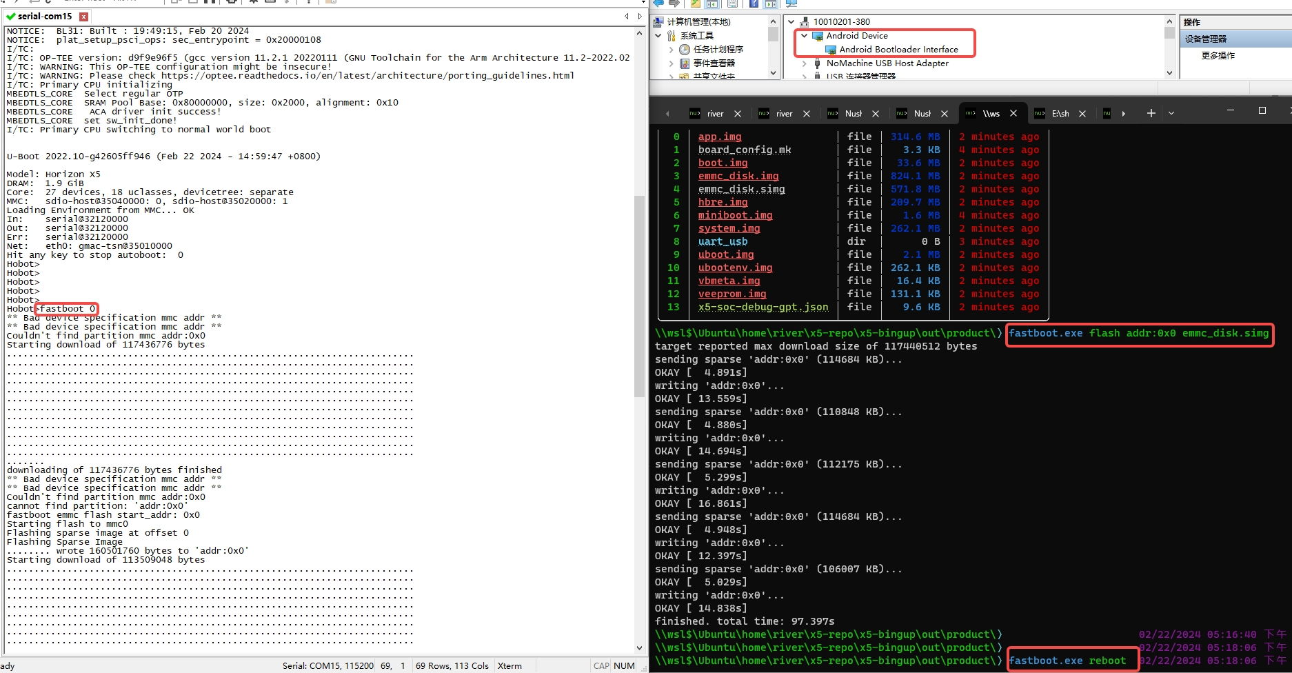
After the development board enters U-Boot command-line mode, execute the fastboot 0 command to enter Fastboot mode.
U-Boot 2022.10-gca2c6582a0 (Mar 13 2024 - 19:04:15 +0800)

Model: Horizon X5
... (omitted) ...
Hobot>fastboot 0
Next, open a Windows PowerShell terminal in the directory where the emmc_disk.simg image is located. In Windows, right-click while holding Shift in the image directory to see:
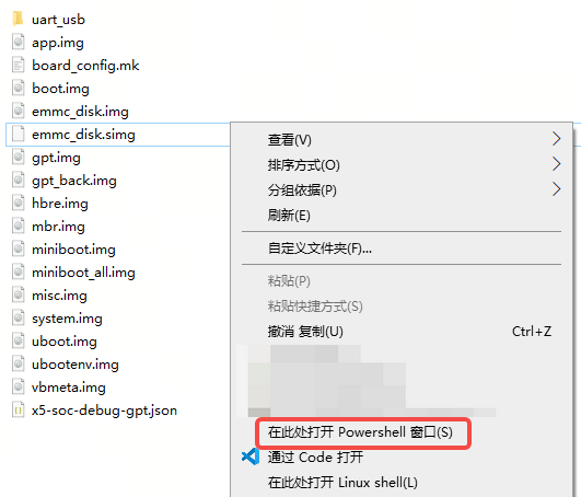
Then, execute the following command in the PowerShell terminal to flash the full system image:
fastboot flash addr:0x0 emmc_disk.simg
After flashing, execute fastboot reboot in the PowerShell terminal to reboot the device, or power cycle the board to apply the update.
The full system image flashing process is illustrated below:
Alternatively, you can flash by individual partitions.
Flash uboot partition
fastboot flash uboot uboot.img
Flash boot partition
fastboot flash boot boot.img
Flash system partition
fastboot flash system system.img
Flash miniboot partition
fastboot flash miniboot miniboot.img
Note:
An alternative method to flash the miniboot partition requires using flash addr:0x0. Use the following command:
fastboot flash addr:0x0 miniboot_all.img
miniboot_all.img refers to a file that includes the miniboot partition and all preceding images, specifically miniboot.img, the partition table, and the misc partition. If you need to update both miniboot and the partition table, you must write from addr:0x0; you cannot flash the miniboot partition alone. This operation is similar to updating emmc_disk.simg, so ensure the correct write format is used.
2.5.5.2. Flashing Images Using dfu Commands
Prerequisites:
Please refer to Connect via USB to complete the installation of the USB driver. On Windows, it usually appears as
Android Bootloader Interfacein Device Manager.Connect the hardware according to the wiring diagram for the GUI tool’s USB download mode wiring method.
Applicable Scenarios:
This flashing method is primarily used for development boards with no image or corrupted images.
It can also be used on boards that already have a valid image and can boot normally.
dfu Command Flashing on Windows
For detailed usage of the dfu command on Windows, please refer to the Using dfu section.
dfu Command Flashing on Ubuntu
Prerequisites (udev rules, plugdev group)
Configure udev rules: Copy the 51-drobotics-usb.rules file to the
/etc/udev/rules.d/directory.Activate the new rules:
udevadm control --reload-rules
udevadm trigger
If the above commands fail to activate, try restarting the computer.
Add the current user to the plugdev group:
sudo usermod -aG plugdev $(whoami)
Log out and back in, then use the
groupscommand to confirm that the user has successfully joined the plugdev group.
Common Commands
The commonly used commands are similar to those on the Windows platform, using thedfu-utiltool for flashing.
2.5.5.3. Manually Flashing Images via Serial Port
Prerequisites:
Refer to Connecting via Serial Port to complete the installation of the serial port driver. In Device Manager on a Windows PC, you should see the corresponding COM port; on Ubuntu, you can find the corresponding tty serial device under the
/devdirectory.Wire the board according to the wiring method for UART download mode in the graphical tool.
For boards with DIP switches, ensure the switches are set to the default boot mode, such as EMMC boot mode.
When flashing images via serial port, it is recommended to set the serial baud rate to 921600 bps (for the X5 EVB, set DIP switch D4 to 1) to improve flashing speed.
Applicable Scenarios:
This flashing method is primarily suitable for development boards without an image or with a corrupted image.
It can also be used on boards that already have an image and can boot normally.
If firmware upgrade via the graphical flashing tool fails and the lack of log information makes it difficult to pinpoint the issue, refer to the manual flashing method described in this section. By booting the system to the U-Boot stage, more detailed boot logs can be obtained to help identify the root cause.
Below are the detailed steps for firmware flashing:
Step 1:
Prepare a serial terminal tool.
The UART download mode requires image transmission via the Xmodem protocol, so a serial tool that supports Xmodem is required. We recommend the open-source tool WindTerm, which runs on both Windows and Linux systems—simply download the appropriate package.
For Windows, download WindTerm_X.X.X_Windows_Portable_x86_64.zip, extract it, and run WindTerm.exe directly.
For Linux, download WindTerm_X.X.X_Linux_Portable_x86_64.zip, extract it, and execute the following command to run:
chmod +x ./WindTerm && ./WindTerm
Step 2:
Connect the device’s serial port to the computer, ensuring the device is powered off.
Step 3:
Use WindTerm to connect to the device’s serial port. In the WindTerm interface, click Session -> New Session from the menu bar to create a serial session, and configure the serial port settings accordingly:
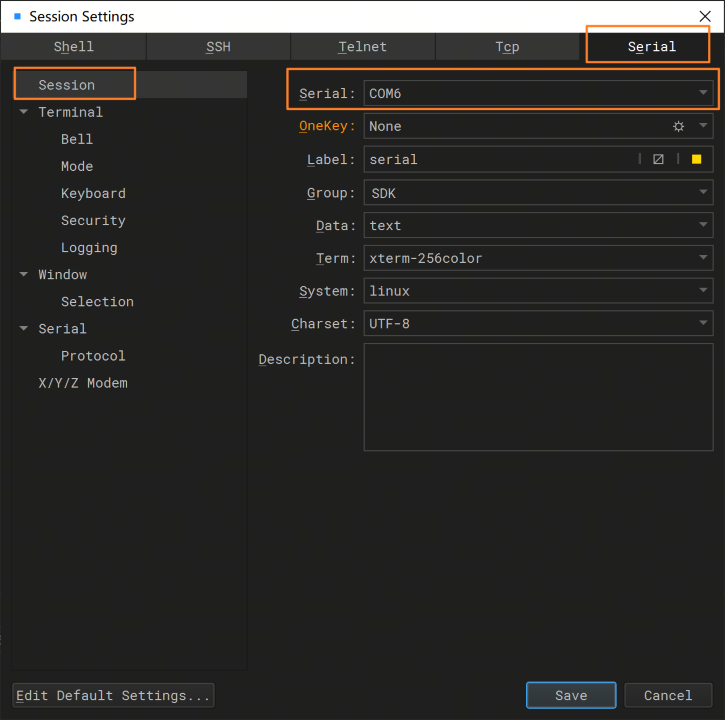
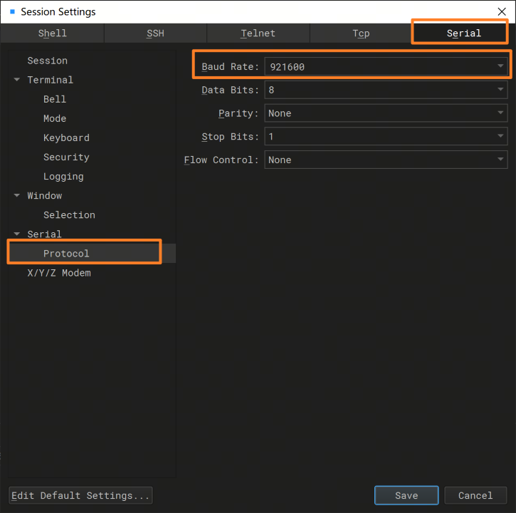
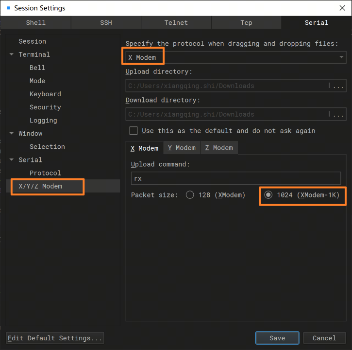
Set the file drag-and-drop protocol to Xmodem, and it is recommended to select a packet size of 1024 to improve file transfer speed.
Step 4:
In the WindTerm interface, click View -> Panes -> Sender from the menu bar to open the Sender window:
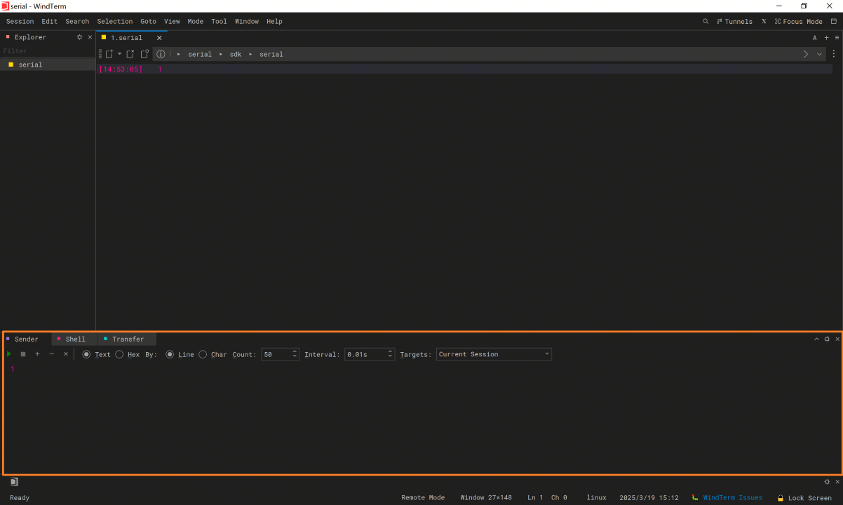
Step 5:
In the Sender window, enter the command x2dbg, and set the execution count to 50 times with an interval of 0.01 seconds:
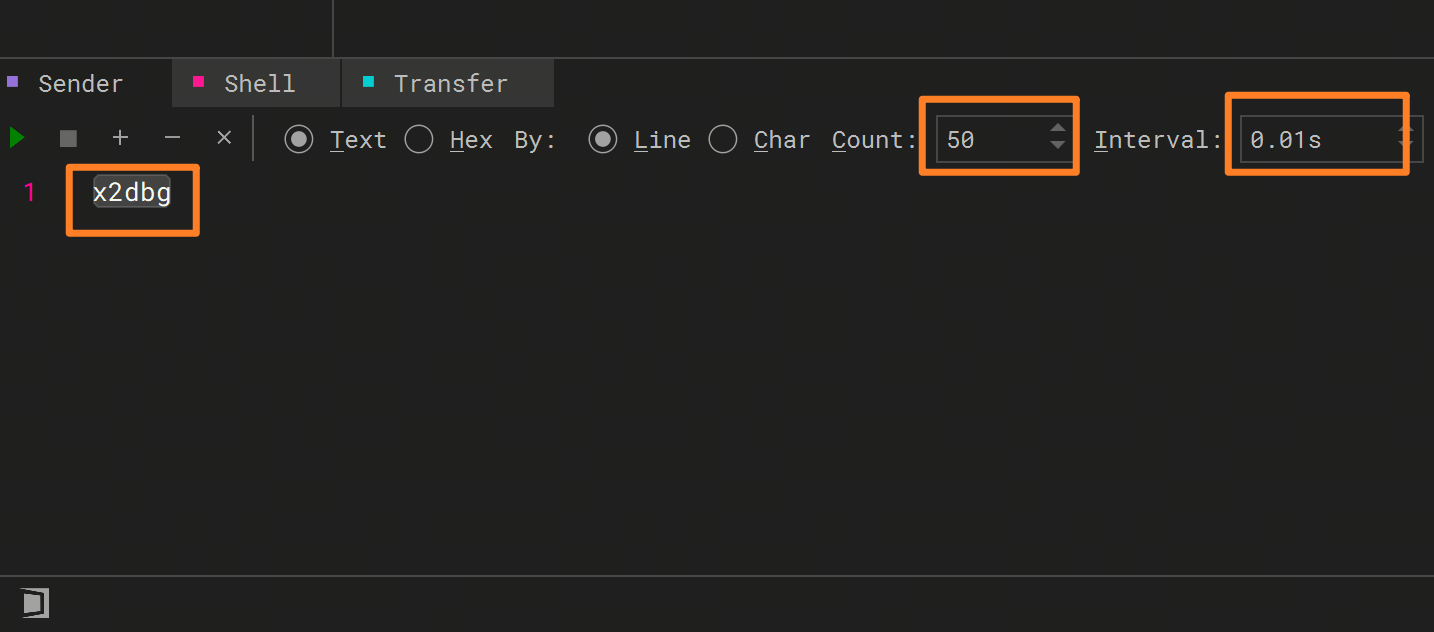
Step 6:
Click run (the green triangle button) to start executing the command in a loop.
Step 7:
Immediately after starting the script, power on the development board. Once powered, the device will enter serial download mode, and the serial terminal will continuously print C, with a prompt indicating Currently use xmodem to download file.
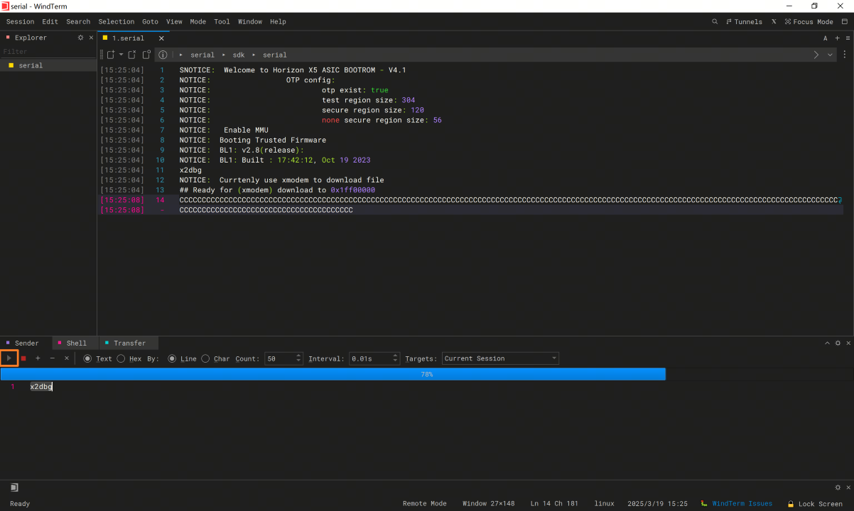
Drag the bl2_uart_ddr.bin firmware file from the out\product\uart_usb directory (after BSP compilation) into the current serial window. Xmodem file transfer will begin automatically:
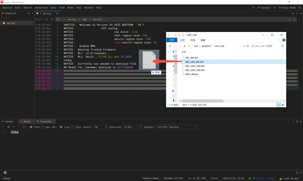
Step 9:
After bl2_uart_ddr.bin is successfully downloaded and executed, the serial log will appear as shown below. At the end of the log, the message Download bl3x fip(bl3x_all.bin) will appear, indicating that the xmodem protocol must be used again to transfer the next firmware. The serial terminal will once again continuously print the character C, waiting for the next action.
 100% [====================] 00:00:10 704360 bytes
00 = 704512 Bytes
NOTICE:  Get S1PK
NOTICE:  [verify_signature] pass.
NOTICE:  [verify_hash] pass.
NOTICE:  [verify_hash] pass.
NOTICE:  [auth_decrypt] pass.
NOTICE:  BL1: BL2 memory layout address = 0x1fe9f000
NOTICE:  BL1: Booting BL2
NOTICE:                 OTP config:
NOTICE:                         otp exist: true
NOTICE:                         test region size: 304
NOTICE:                         secure region size: 120
NOTICE:                         none secure region size: 56
NOTICE:  BL2: v2.8(release):v1.0.8-72-g68feecd07
NOTICE:  BL2: Built : 15:17:38, Jan 16 2025
NOTICE:  Enter UART Mode.....
NOTICE:  Enter media_source_select process(0).
NOTICE:  BL2 config file
NOTICE:  start to load bl2 cfg image
NOTICE:  BL2 CFG ADDR:0x1ff00000, MAGIC:0x474643324c424248
NOTICE:  bypass update efuse
NOTICE:  calibration_offset -22
NOTICE:  trimming_value 9
NOTICE:  ADC read channel[2]: 313mv
NOTICE:  ddr info:[LPDDR4]-[DUAL_RANK]-[ECC OFF]-[DVFS ON]-[4266M]
NOTICE:  JTAG ENABLE
NOTICE:  disable wdt
NOTICE:  Get S1PK
NOTICE:  [verify_signature] pass.
NOTICE:  [verify_hash] pass.
NOTICE:  [verify_signature] pass.
NOTICE:  start to load ddr image
NOTICE:  [verify_hash] pass.
NOTICE:  run ddr Fw
NOTICE:  matching profile: profile_2 from aon config
NOTICE:  type: LP4, freq: 4266, ecc: 0(0x7f), rank: 2, dvfs: 1, version: 9.03
NOTICE:  ddr cost: 146803 us, ddr size: 4 GB, manuid: 0x13
NOTICE:  ddr ready
NOTICE:  Download bl3x fip(bl3x_all.bin) to ddr: 0x84000000
NOTICE:  Currtenly use xmodem to download file
## Ready for (xmodem) download to 0x84000000
CCCCCCCCCCCCCCCCCCCC
Step 10:
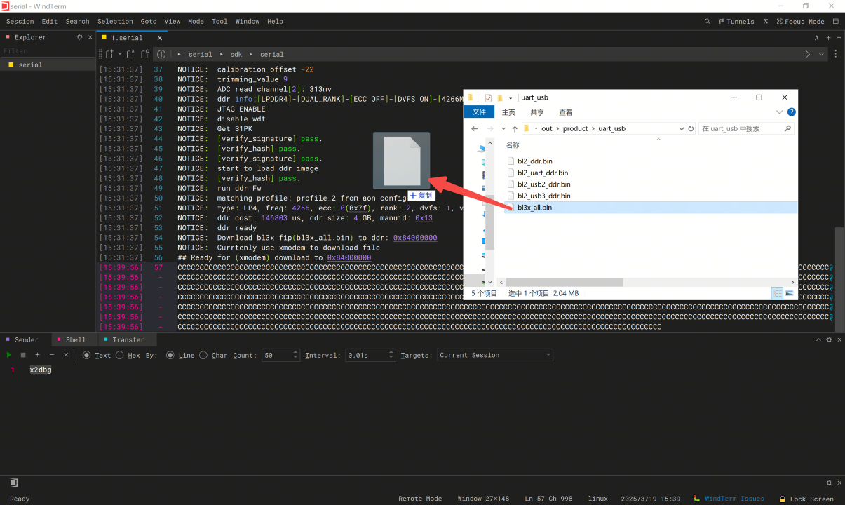
Similar to Step 8, drag the bl3x_all.bin firmware file from the out\product\uart_usb directory (after BSP compilation) into the current serial window. Xmodem file transfer will begin automatically. This firmware is relatively large; if the baud rate is set to 115200 bps, the transfer will be slow—please be patient until the transfer completes.
Step 11:
After bl3x_all.bin is successfully transferred and executed, the device will enter U-Boot command-line mode. In this mode, you can choose to flash firmware using the fastboot command, or manually download images via tftp.
The serial log will appear as follows:
100% [====================] 00:00:32 2144940 bytes
00 = 2145280 Bytes
NOTICE:  Get S1PK
NOTICE:  [verify_signature] pass.
NOTICE:  [verify_hash] pass.
NOTICE:  [verify_signature] pass.
NOTICE:  start to load bl31 image
NOTICE:  [verify_hash] pass.
NOTICE:  Get S1PK
NOTICE:  [verify_signature] pass.
NOTICE:  [verify_hash] pass.
NOTICE:  [verify_signature] pass.
NOTICE:  start to load optee image
NOTICE:  [verify_hash] pass.
NOTICE:  [verify_hash] pass.
NOTICE:  start to load uboot image
NOTICE:  BL1: Booting BL31
NOTICE:  multicore_init: sec_entrypoint = 0x2000010c
NOTICE:  BL31: v2.8(release):v1.0.8-67-g40e41bd29
NOTICE:  BL31: Built : 10:40:46, Dec 31 2024
NOTICE:  plat_setup_psci_ops: sec_entrypoint = 0x2000010c
I/TC:
I/TC: OP-TEE version: 6b9fbbe87 (gcc version 11.3.1 20220712 (Arm GNU Toolchain 11.3.Rel1)) #1 Thu Jan 16 06:59:55 UTC 2025 aarch64
I/TC: WARNING: This OP-TEE configuration might be insecure!
I/TC: WARNING: Please check https://optee.readthedocs.io/en/latest/architecture/porting_guidelines.html
I/TC: Primary CPU initializing
MBEDTLS_CORE  Select regular OTP
MBEDTLS_CORE  SRAM Pool Base: 0x80000000, size: 0x2000, alignment: 0x10
MBEDTLS_CORE   ACA driver init success!
MBEDTLS_CORE  set sw_init_done!
I/TC: Primary CPU switching to normal world boot


U-Boot 2022.10-gd5c668dae2 (Mar 14 2025 - 17:56:43 +0800)

Model: Horizon X5
DRAM:  3.9 GiB
console out start addr:0x0000000087ffc000, end addr:0x0000000087ffe000
horizon_lsio_pinctrl lsio_iomuxc@34180000: Initialized D-Robotics pinctrl driver
optee optee: OP-TEE: revision 3.20 (6b9fbbe8)
ADC calibration: -22
ADC trimming: 9
horizon_hsio_pinctrl hsio_iomuxc@35050000: Initialized D-Robotics pinctrl driver
horizon_dsp_pinctrl dsp_iomuxc@31040014: Initialized D-Robotics pinctrl driver
Core:  149 devices, 29 uclasses, devicetree: separate
WDT:   Started watchdog@34250000 with servicing (10s timeout)
stop watchdog
MMC:   sdio-host@35040000: 0, sdio-host@35020000: 1
Loading Environment from MMC... (Tuning Ok!) *** Warning - bad CRC, using default environment

In:    serial@32120000
Out:   serial@32120000
Err:   serial@32120000
Net:
Warning: gmac-tsn@35010000 (eth0) using random MAC address - 36:64:fc:52:5e:1e
eth0: gmac-tsn@35010000
boot action: UART
Hobot>
Ensure all steps are followed correctly to successfully complete the firmware flashing and upgrade.
2.5.6. FAQ: Common Error Reference Table
2.5.6.1. Environment Preparation Issues
Issue: Detect burn state error
Error Message
[Burn thread-1][11:46:37] [INFO] burn_flow.py:271 Please try enter UART download mode
[Burn thread-1][11:46:37] [INFO] serial_transport.py:746 Try entry UART download mode...
[Burn thread-1][11:46:37] [WARNING] serial_transport.py:748 [IMPORTANT] Please power on or reboot the Board! Wait 30 seconds...
[Burn thread-1][11:47:07] [WARNING] serial_transport.py:763 Entry UART download mode timed out after 30 seconds.
[Burn thread-1][11:47:07] [ERROR] burn_flow.py:273 Failed to enter UART download mode, Board state: UNKNOWN
[Burn thread-1][11:47:07] [ERROR] burn_executor.py:57 Step 'prepare_boot' failed
[Burn thread-1][11:47:07] [ERROR] xburn.py:91 Board-1, burn failed
[Burn thread-1][11:47:07] [ERROR] xburn.py:75 Board-1 [Storage: nand] Status: FAILED
Process terminated, exit code: 0
Solution
When the tool prompts “Please power on or reboot the Board! Wait 30 seconds…”, reboot the development board
Recommended operation order: first click the tool’s
Start Upgrade, then power on the development board
Issue: Serial port not connected
Error Message
[MainThread][10:54:37] [ERROR] cli_utils.py:573 Serial port COM8 is NOT available
[MainThread][10:54:37] [ERROR] cli_utils.py:575 Reason:
Port COM8 not found.
Please check:
1. Is the device properly connected?
2. Is the correct port name used?
3. Available ports: python -m serial.tools.list_ports
[MainThread][10:54:37] [ERROR] xburn.py:368 Invalid configuration.
Process terminated, exit code: 1
Solution
Check if the serial USB cable is connected
Check if the USB driver is installed
Check if the serial port is occupied by another terminal
Return to the main interface to refresh the serial port and select the correct COM port
Issue: Image path abnormal or image does not exist
Error Message
[MainThread][10:58:00] [ERROR] cli_utils.py:427 Set storage type failed.
[MainThread][10:58:00] [ERROR] cli_utils.py:584 The img_files parameter validation failed. Exiting...
[MainThread][10:58:00] [ERROR] xburn.py:368 Invalid configuration.
Solution
Check if the image path is correct. The default flashable image path in the SDK is
out/productCheck if the required image files exist under the specified image path
Issue: Cannot find dfu device
Error Message
dfu-util 0.11
Copyright 2005-2009 Weston Schmidt, Harald Welte and OpenMoko Inc.
Copyright 2010-2021 Tormod Volden and Stefan Schmidt
This program is Free Software and has ABSOLUTELY NO WARRANTY
Please report bugs to http://sourceforge.net/p/dfu-util/tickets/
dfu-util: Warning: Invalid DFU suffix signature
dfu-util: A valid DFU suffix will be required in a future dfu-util release
dfu-util: No DFU capable USB device available
Solution
Check if it is in USB 2.0 DFU boot mode
Check the USB cable connection status
Check if the USB driver is installed
2.5.6.2. Firmware Type Errors
Issue: Flashing Non-Secure firmware on a Secure chip
Error Message
[Burn thread-1][18:05:09] [INFO] uart_boot.py:66 load success
NOTICE: Get S1PK
NOTICE: [verify_signature] pass.
ERROR: Hash value not match.
ERROR: Failed to load extension FW ID 1
ERROR: horizon_dfu_dnl_fip failed
ERROR: Uart Preemption Download fip failed, ReDownLoad!!
Solution
Flashing Non-Secure firmware on a Secure chip will report a hash verification failure. For Secure and Non-Secure firmware compilation, refer to Non-secure Firmware
Issue: Flashing Secure firmware on a Non-Secure chip
Error Message
[Burn thread-1][17:54:58] [PROGRESS] burn_progress.py:21 Board 1 burn progress 15.5%
[Burn thread-1][17:54:58] [INFO] uart_boot.py:66 load success
00 = 708608 Bytes
NOTICE: BL1: BL2 memory layout address = 0x1fe9f000
NOTICE: BL1: Booting BL2
E[Burn thread-1][17:56:38] [ERROR] uart_boot.py:81 Uart xmodem download uart_usb/bl3x_all.bin failed
[Burn thread-1][17:56:38] [ERROR] burn_executor.py:57 Step 'xmodem_boot' failed
[Burn thread-1][17:56:38] [ERROR] xburn.py:91 Board-1, burn failed
[Burn thread-1][17:56:38] [ERROR] xburn.py:75 Board-1 [Storage: emmc] Status: FAILED
Process terminated, exit code: 0
Solution
Flashing Secure firmware on a Non-Secure chip will get stuck at the Booting BL2 stage until the flashing times out. For Secure and Non-Secure firmware compilation, refer to Non-secure Firmware
2.5.6.3. Flashing Process Issues
Issue: Xmodem error “send error: expected ACK; got b’C’ for block 1”
Error Message
[Burn thread-1][2026-07-02 11:42:04,689] [PROGRESS] burn_progress.py:21 Board 1 burn progress 18.2%
[Burn thread-1][2026-07-02 11:42:04,689] [INFO] serial_transport.py:83 Transfer: 59.4% | Blocks: 940/1582
[Burn thread-1][2026-07-02 11:42:06,094] [ERROR] __init__.py:338 send error: expected ACK; got b'\x15' for block 1
[Burn thread-1][2026-07-02 11:42:06,107] [ERROR] __init__.py:338 send error: expected ACK; got b'\x15' for block 1
[Burn thread-1][2026-07-02 11:42:06,117] [ERROR] __init__.py:338 send error: expected ACK; got b'\x15' for block 1
Solution
Check the serial connection stability
Lower the serial baud rate and retry. For the X5 EVB board, you can set the DIP switch D4 to 0 and adjust the baud rate to 115200
If using a customized motherboard with an external serial module, check the cable connection status, whether the ground wire is connected, etc.
Issue: Cannot find fastboot device
Error Message
[DeviceScannerThread][14:33:53] [INFO] usb_device_manager.py:246 Scan fastboot [21]round: timeout 3s
[DeviceScannerThread][14:33:53] [INFO] run_host_cmd.py:240 Executing 'tools/windows/fastboot.exe devices', waiting for 3 seconds for execution to finish...
[DeviceScannerThread][14:33:54] [INFO] usb_device_manager.py:246 Scan fastboot [22]round: timeout 3s
[DeviceScannerThread][14:33:54] [INFO] run_host_cmd.py:240 Executing 'tools/windows/fastboot.exe devices', waiting for 3 seconds for execution to finish...
[Burn thread-1][14:33:56] [WARNING] usb_transport.py:196 Wait for state Fastboot Mode timed out
[Burn thread-1][14:33:56] [ERROR] fastboot_burn.py:159 Not found usb2.0
Solution
Check if the USB driver is installed
Check the USB cable connection status
Fastboot device startup depends on the development board’s U-Boot; check if U-Boot starts normally
Issue: Fastboot error “Too many links”
Error Message
FAILED (Status read failed (Too many links))
fastboot: error: Command failed
Analysis
This is a common fastboot error. The error typically appears as Status read failed (Too many links) or data transfer failure (Too many links), meaning the data transfer between the computer and the device is unstable or interrupted.
Solution
Check the USB cable connection status; check the quality of the USB data cable or USB interface
Computer compatibility issues: some computers’ USB 3.0 interfaces may have compatibility issues, causing transfer failures