2.4. Connect the Development Board
This chapter aims to provide users with detailed instructions for connecting the development board. It introduces three connection methods—serial port, USB, and network interface—along with corresponding driver installation, operation guidelines, and precautions.
Note:
The default username for the development board is
root, and the password isroot.All drivers and software packages involved in this chapter can be downloaded online from the software_tools page, or directly obtained from the
software_toolsdirectory in the SDK delivery package.
2.4.1. Connecting via Serial Port
The serial port serves as the most fundamental debugging interface for the development board and is frequently used in scenarios such as functional debugging and image upgrades.
2.4.1.1. Hardware Connection
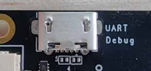
The X5 EVB development board already includes a USB-to-serial chip (CH340N). Users can connect the board to a personal computer (PC) using a Micro USB 2.0 data cable. After installing the CH340N driver on the PC, the serial interface becomes usable. The physical interface is labeled as interface 19 in the Functional Module Layout, as shown in the figure below:
2.4.1.2. Using Serial Port on Windows
Install Driver
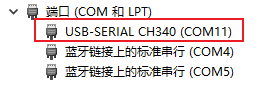
To use the serial port on Windows, you must first install the CH340 driver. The corresponding driver can be found in the SDK delivery package under software_tools/serial_to_usb_drivers. After completing the driver installation, a COM device should appear in Device Manager as shown below:
Connecting and Usage
Commonly used terminal tools on PC include Putty, MobaXterm, SecureCRT, etc. Users may choose based on preference. The configuration process across different tools is similar. This document uses SecureCRT as an example to illustrate how to create a new serial connection.
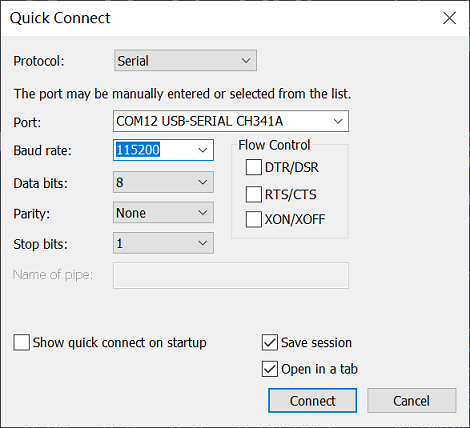
The serial port configuration parameters on the PC are as follows:
Baud rate: 115200
Data bits: 8
Parity: None
Stop bits: 1
Flow control: None
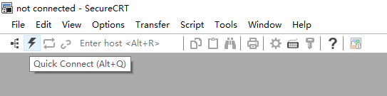
Click the Quick Connect button to open the creation window.
In the Quick Connect dialog, set Protocol to Serial, select the detected COM port (e.g., COM12) as Port, and configure according to the above parameters.
Click the Connect button in the Quick Connect dialog to complete the connection.
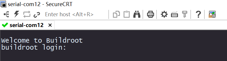
Enter username
rootand passwordrootto log in to the device.
2.4.1.3. Using Serial Port on Ubuntu
Ubuntu systems typically come with built-in USB-to-Serial converter drivers. Once the development board’s serial port is connected to the PC, a device node /dev/ttyUSB* (* represents a number) will be created.
On Ubuntu, you can use software such as minicom or picocom to connect to the serial port. The following example uses minicom.
Using minicom
sudo apt-get install minicom
After connecting the serial cable, run ls /dev/ttyUSB* to confirm the serial device node. In the example below, it is /dev/ttyUSB0:
$ ls /dev/ttyUSB*
/dev/ttyUSB0
Run minicom with sudo privileges:
$ sudo minicom -D /dev/ttyUSB0
Welcome to minicom 2.7.1

OPTIONS: I18n
Compiled on Dec 23 2019, 02:06:26.
Port /dev/ttyUSB0, 11:55:56

Press CTRL-A Z for help on special keys
The message indicates that CTRL-A Z is the escape key combination. Press Ctrl-A, release, then press Z to bring up the help menu.
   +-------------------------------------------------------------------+
                          Minicom Command Summary                      |
  |                                                                    |
  |              Commands can be called by CTRL-A <key>                |
  |                                                                    |
  |               Main Functions                  Other Functions      |
  |                                                                    |
  | Dialing directory..D  run script (Go)....G | Clear Screen.......C  |
  | Send files.........S  Receive files......R | cOnfigure Minicom..O  |
  | comm Parameters....P  Add linefeed.......A | Suspend minicom....J  |
  | Capture on/off.....L  Hangup.............H | eXit and reset.....X  |
  | send break.........F  initialize Modem...M | Quit with no reset.Q  |
  | Terminal settings..T  run Kermit.........K | Cursor key mode....I  |
  | lineWrap on/off....W  local Echo on/off..E | Help screen........Z  |
  | Paste file.........Y  Timestamp toggle...N | scroll Back........B  |
  | Add Carriage Ret...U                                               |
  |                                                                    |
  |             Select function or press Enter for none.               |
  +--------------------------------------------------------------------+
As prompted, press O to enter the setup interface:
           +-----[configuration]------+
           | Filenames and paths      |
           | File transfer protocols  |
           | Serial port setup        |
           | Modem and dialing        |
           | Screen and keyboard      |
           | Save setup as dfl        |
           | Save setup as..          |
           | Exit                     |
           +--------------------------+
Move the cursor to Serial port setup and press Enter to enter the serial port configuration interface. Then input the corresponding letters to select options and set them according to the parameters listed above:
   +-----------------------------------------------------------------------+
   | A -    Serial Device      : /dev/ttyUSB0                              |
   | B - Lockfile Location     : /var/lock                                 |
   | C -   Callin Program      :                                           |
   | D -  Callout Program      :                                           |
   | E -    Bps/Par/Bits       : 115200 8N1                               |
   | F - Hardware Flow Control : No                                        |
   | G - Software Flow Control : No                                        |
   |                                                                       |
   |    Change which setting?                                              |
   +-----------------------------------------------------------------------+
Note: Both Hardware Flow Control and Software Flow Control must be set to No, otherwise input may not work.
After configuration, press Enter to return to the previous menu, select Save setup as dfl, and press Enter to save as the default configuration, which will be used automatically in future sessions.
2.4.2. Connecting via Network Interface
The development board supports one Gigabit Ethernet interface. The module interface is marked as interface 4 in the Functional Module Layout. Users can remotely log in to the development board via network (SSH, etc.). The board defaults to supporting the SSH2 communication protocol.
Users can choose one of the following two network connection methods:
Direct connection between the development board and PC. To avoid additional interference from network environments, this document recommends using direct PC connection as the preferred method.
Both the development board and PC are connected to the same local area network (LAN). Since the development board does not use DHCP by default, when connecting to a LAN, ensure that static IP assignment is supported.
To ensure normal network communication, users must verify that both the development board and PC network configurations meet the following requirements:
Both IP addresses are within the same subnet (i.e., the first few segments of the IP address are identical). For example, development board IP:
192.168.1.10, PC IP:192.168.1.100Both have the same subnet mask (255.255.255.0) and gateway (192.168.1.1)
Disable the PC’s firewall
To check the current network configuration of the development board, execute the ifconfig command. The default network configuration of the development board is currently:
IP address: 192.168.1.10
Netmask: 255.255.255.0
Gateway: 192.168.1.1
To configure the development board’s network, use the command:ifconfig <target eth dev> <target ip> netmask <target netmask>
For example, to configure the eth0 interface with IP 192.168.1.110 and netmask 255.255.254.0, run:ifconfig eth0 192.168.1.110 netmask 255.255.254.0
For more command details, refer to the ifconfig Manual Page.
To configure the development board’s gateway, refer to the route Manual Page.
After confirming the development board’s network settings, configure the PC’s network parameters accordingly.
2.4.2.1. Windows Network Configuration
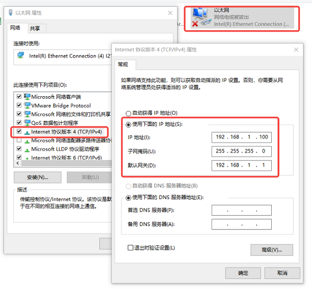
Example: Configure PC IP as follows:
IP address: 192.168.1.100
Netmask: 255.255.255.0
Gateway: 192.168.1.1
Steps:
In Network Connections, locate the corresponding Ethernet device and double-click to open it.
Find Internet Protocol Version 4 (TCP/IPv4) and double-click to open.
Enter the network parameters in the red box area as shown in the image below, then click OK.
2.4.2.2. Ubuntu Network Configuration
Example: Configure PC IP as follows:
IP address: 192.168.1.100
Netmask: 255.255.255.0
Gateway: 192.168.1.1
Steps:
On the Ubuntu desktop, open
System Settings→ clickNetwork→ locate the wired connection interface connected to the board (if not directly connected, identify the interface communicating with the board), and click the gear icon next to it.In the pop-up window, switch to the
IPv4tab for configuration.Select
Manual, enter theAddress,Netmask, andGateway, clickApply, and restart the network.
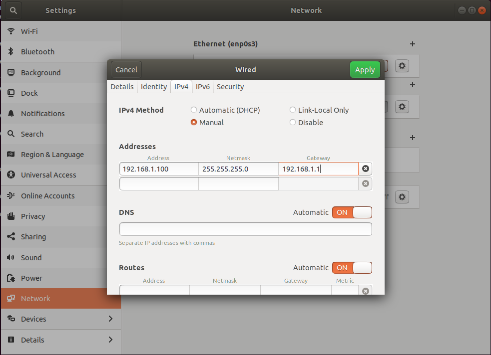
After completing the network configuration, verify bidirectional ping connectivity between the development board and PC. If ping fails, recheck the configuration against the network requirements.
2.4.2.3. Terminal Software Configuration
Commonly used PC debugging tools include Putty, MobaXterm, SecureCRT, etc. Users can choose based on preference. The process of connecting to the development board via network is generally similar across tools. This document uses SecureCRT as an example to demonstrate creating a new network connection.
Click the Quick Connect button and set Protocol to SSH2.
Set Hostname to the development board IP address (192.168.1.10). For SSH2, also enter Username as root.
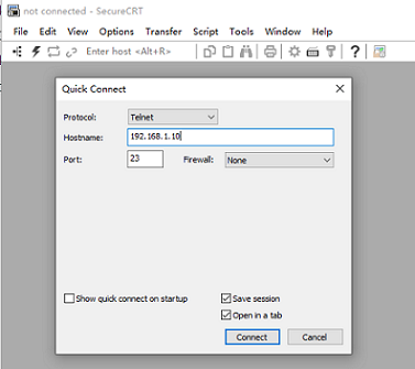
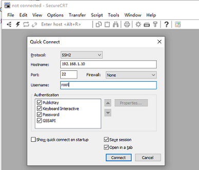
Keep other settings default and click Connect to complete setup.
For Telnet login, enter username (
root) and password (root).For SSH2 login, only password (
root) is required.
2.4.3. Connecting via USB Port
The development board features a Micro USB 2.0 interface (interface 5 in the Functional Module Layout), configured by default in Device mode. This interface supports multiple functions, including ADB (enabled by default), as well as protocols such as Fastboot, DFU, RNDIS, and ECM.
2.4.3.1. Installing Software on Windows
Installing USB Drivers
For Windows operating systems, ensure the appropriate drivers are installed before using adb and fastboot functions.
Enter fastboot 0 at the development board’s U-Boot command line to enter fastboot mode:
U-Boot 2022.10-gc52e405209 (Nov 26 2024 - 14:20:51 +0800)

Model: Horizon X5
... (omitted) ...
Hit any key to stop autoboot:  0
Hobot>
Hobot>fastboot 0
select emmc(0) as flash medium
do fastboot usb
If the driver is not installed, Device Manager will show an unknown device labeled USB download gadget, as shown below:
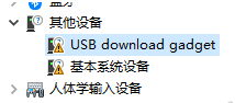
In this case, use the software_tools\winusb_drivers\sunrise5_winusb.zip package from the SDK delivery package to install the driver:
Extract sunrise5_winusb.zip.
Navigate into the
sunrise5_winusbfolder, right-clickinstall_driver.bat, and select Run as administrator.
After successful installation, Device Manager will display an Android Device, as shown below:
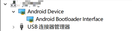
Installing USB Tools
Locate the file software_tools\adb_and_fastboot\platform-tools_r34.0.5-windows.zip in the SDK delivery package. Follow these steps to install the software and set environment variables:
Extract
platform-tools_r34.0.5-windows.zipto a folder without spaces, Chinese characters, or special characters, e.g.,D:\platform-tools.
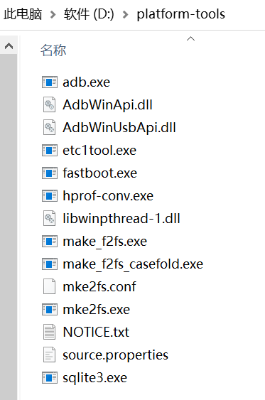
Open the Windows system advanced environment settings and add the extracted tool path to the system PATH variable.
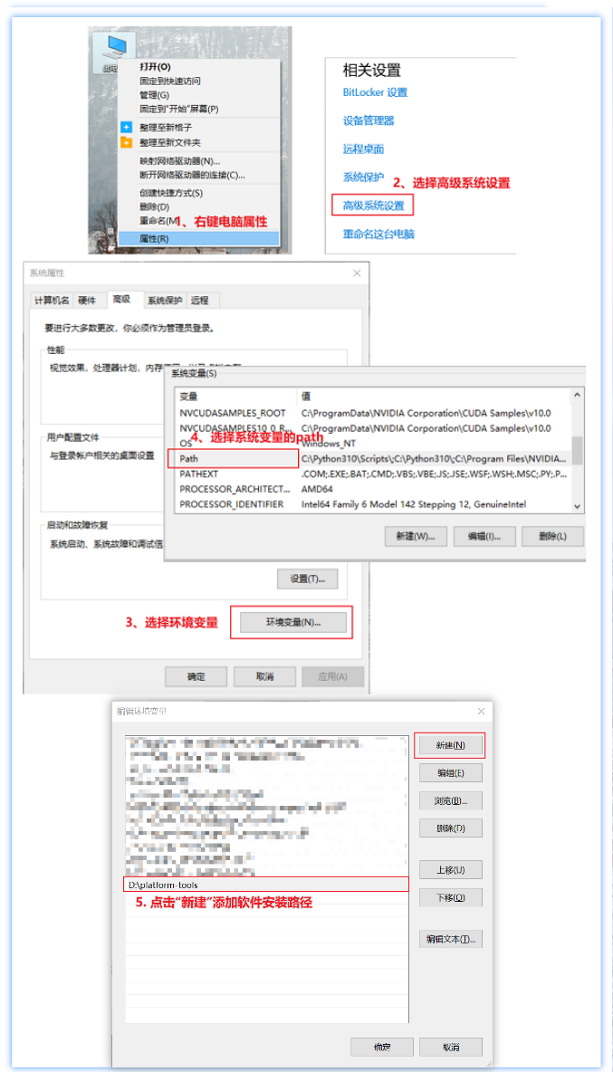
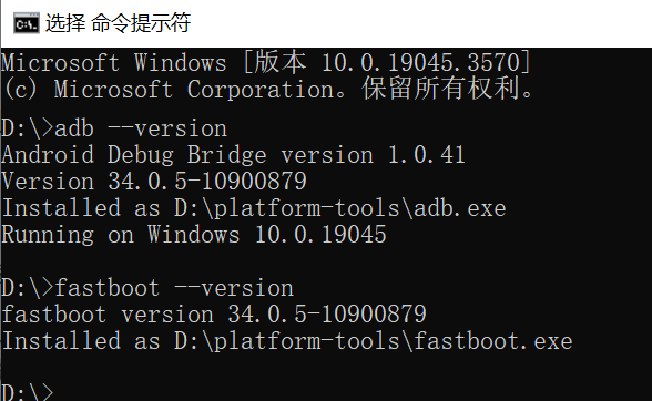
After correctly configuring the environment variables, open Command Prompt and run adb --version and fastboot --version to verify the tool versions.
Note:
To use the ramdump debugging feature, install the fastboot tool from software_tools\adb_and_fastboot\fastboot.tar.gz, which supports the oem ramdump command.
2.4.3.2. Installing Software on Ubuntu
Installing USB Drivers
Linux hosts such as Ubuntu do not require additional drivers for the above interfaces.
Most Linux systems on Apple computers are also driver-free.
However, Ubuntu requires udev rule configuration; otherwise, sudo privileges are needed to operate dfu, fastboot, and similar devices.
Configure udev rules: copy
software_tools/adb_and_fastboot/51-drobotics-usb.rulesto/etc/udev/rules.d:sudo cp software_tools/adb_and_fastboot/51-drobotics-usb.rules /etc/udev/rules.d
Reload the new rules:
sudo udevadm control --reload-rules
sudo udevadm trigger
Add the current user to the plugdev group:
sudo usermod -aG plugdev $(whoami)
Re-login to the shell and use the
groupscommand to verify group membership.
Installing USB Tools
Run the following commands to install adb, fastboot, and dfu on Ubuntu:
sudo apt install android-tools-adb
sudo apt install android-tools-fastboot
sudo apt-get install dfu-util
Check the adb version:
$ adb --version
Android Debug Bridge version 1.0.39
Version 1:8.1.0+r23-5ubuntu2
Installed as /usr/lib/android-sdk/platform-tools/adb
Check the fastboot version:
$ fastboot --version
fastboot version 1:8.1.0+r23-5ubuntu2
Installed as /usr/lib/android-sdk/platform-tools/fastboot
Check the dfu-util version:
$ dfu-util --version
dfu-util 0.9

Copyright 2005-2009 Weston Schmidt, Harald Welte and OpenMoko Inc.
Copyright 2010-2016 Tormod Volden and Stefan Schmidt
This program is Free Software and has ABSOLUTELY NO WARRANTY
Please report bugs to http://sourceforge.net/p/dfu-util/tickets/
Note: To use the ramdump debugging feature, install the fastboot tool from software_tools\adb_and_fastboot\fastboot.tar.gz, which supports the oem ramdump command.
2.4.3.3. Using adb
After the development board boots, the adbd service starts automatically. Once the board is connected to the PC via USB, you can use adb shell for debugging.
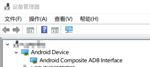
When the development board’s Micro USB is connected to the PC, Device Manager will recognize the adb device as Android Composite ADB Interface, as shown below:
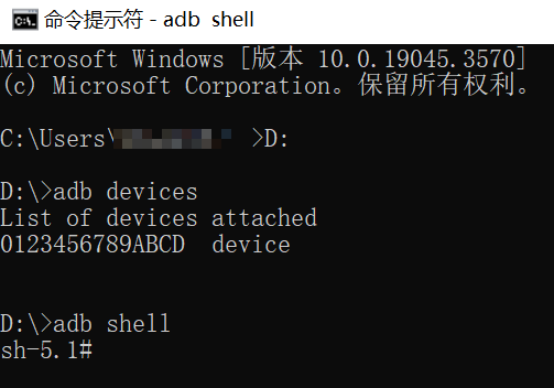
Alternatively, users can run the adb devices command to confirm whether the PC has recognized the adb device. Normal recognition status is shown below:
Failure to recognize the adb device usually has two possible causes:
The Micro USB data cable used does not support data communication, preventing the PC from recognizing the device;
The development board has not started the
adbdservice.
Users can troubleshoot as follows:
Log in to the development board via serial or network, and run
ps | grep adbdto check if theadbdprocess is running;If the
adbdprocess is not running, start it with the command/etc/init.d/usb-gadget.sh restart adb. Example output:Detecting platform: board : Horizon Robotics X5 SOM board udc : 35300000.dwc3 ... (omitted) ... OK Creating Config Init functions... funciton_init, but do nothing, please init on[ 378.910299] file system registered demand OK Bind functions... Bind functions according to .usb-config file bind adb... ... (omitted) ... Binding USB Device Controller OK Run some userspace daemons(eg. usb_camera)... usb-gadget start succeed. usb-gadget restart succeed.
If the
adbdprocess is running but the PC still cannot detect the adb port, verify theMicro USBdata cable for faults.
Common Commands
adb shell
adb pull
adb push

# adb shell does not currently export related environment variables. Manual configuration is required; otherwise, some programs may fail to run due to missing variables. Either of the following methods resolves this:
# Method 1: Manually source /etc/profile after connecting
adb shell
source /etc/profile

# Method 2: Use the command below. Note: Tab completion may not work with this method
adb shell "ENV=/etc/profile sh -i"
2.4.3.4. Using fastboot
Fastboot is primarily used to upgrade software on the development board via USB. Below are two methods to enter fastboot mode:
Method 1: After booting into the shell, run
reboot -m usb2 -f. Upon reboot, the board will automatically enter fastboot mode:# reboot -m usb2 -f 155.850561] reboot: Restarting system with command 'usb2' ... (omitted) ... boot action: FASTBOOT USB2.0 select emmc(0) as flash medium do fastboot usb
Method 2: Enter U-Boot command line mode and run
fastboot 0:U-Boot 2022.10-gc52e405209 (Nov 26 2024 - 14:20:51 +0800) Model: Horizon X5 ... (omitted) ... Hit any key to stop autoboot: 0 Hobot> Hobot>fastboot 0 select emmc(0) as flash medium do fastboot usb
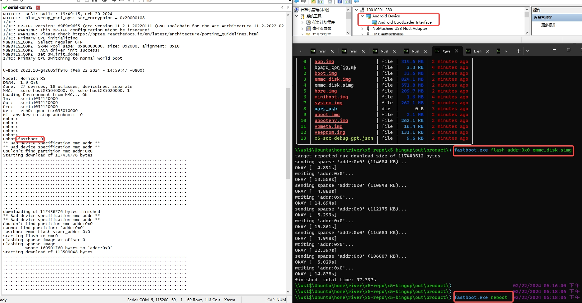
The easiest way to flash the full system image is:
fastboot flash addr:0x0 emmc_disk.simg
After flashing, run fastboot reboot on the host PC or power-cycle the board to apply the update.
The full system image flashing process is illustrated below:
Traditional partition-by-partition flashing is also supported:
fastboot flash uboot uboot.img          # Flash uboot partition
fastboot flash miniboot miniboot.img    # Flash miniboot partition
fastboot flash boot boot.img            # Flash boot partition
fastboot flash system system.img        # Flash system partition
Note:
When flashing
miniboot_all, do not use the partition nameminiboot. Instead, useflash addr:0x0, e.g.:
fastboot flash addr:0x0 miniboot_all.img
Reason: miniboot_all.img includes all images before the U-Boot partition (i.e., miniboot.img, partition table, and misc partition). To update both miniboot and the partition table together, it must be written from addr:0x0, just like emmc_disk.simg, and cannot be flashed to the miniboot partition alone.
It is recommended to connect the PC and development board directly via USB cable. Avoid using a USB hub, as it may affect transmission stability and cause flashing failure.
2.4.3.5. Using dfu
DFU is primarily used to upgrade software on the development board via USB.
After entering the U-Boot command line mode, run dfu 0 to enter DFU mode. If no image has been flashed to the storage medium (eMMC or NAND flash), and there is no valid partition table, run run dfu_emmc.
U-Boot 2022.10-gca2c6582a0 (Mar 13 2024 - 19:04:15 +0800)

Model: Horizon X5
... (omitted) ...
Hobot>dfu 0
DFU alt info setting: done
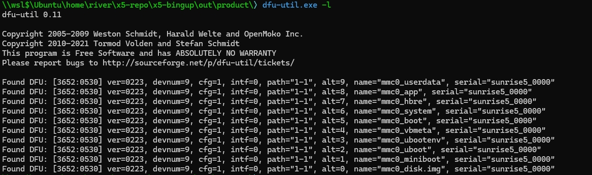
View partitions on the PC side, and select the corresponding type through -a to burn the entire or partitioned burn:
dfu-util -l
For example, the reference image partition table is shown in the figure below:
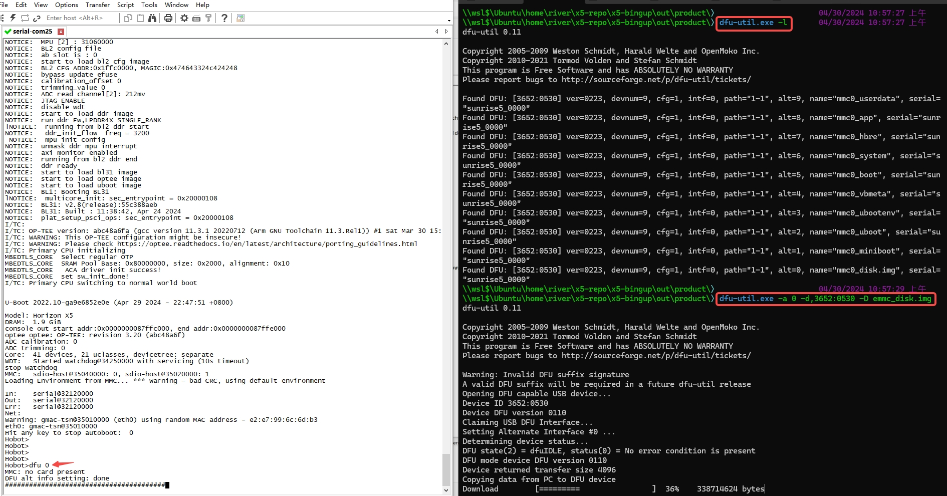
Flashing the full system image:
dfu-util -a 0 -D emmc_disk.img

# If there are multiple DFU devices on the host (e.g., some laptop cameras are also DFU devices), use the -d parameter to specify the device ID:
# The comma is required. DFU devices have both run-time and DFU modes; the ID after the comma matches the DFU mode device.
dfu-util -d,3652:0530 -a 0 -D emmc_disk.img
The process of flashing the full system image is illustrated below:
Flashing by partition:
# Refer to the partition information listed by `dfu-util -l` for the actual partition number (i.e., the number after -a)
dfu-util -a 2 -D uboot.img                      # Flash uboot partition
dfu-util -a 5 -D boot.img                       # Flash boot partition
dfu-util -a 6 -D system.img                     # Flash system partition
2.4.3.6. Virtual Network Interface Introduction
When dealing with USB virtual network interfaces, two common protocols are typically encountered: RNDIS (Remote NDIS) and CDC-ECM (Ethernet Control Model). Each has distinct purposes and application scenarios:
RNDIS (Remote NDIS):
Brief Introduction: RNDIS (Remote Network Driver Interface Specification) is a Microsoft variant implementation of CDC-ECM, primarily designed to simplify USB network device driver development on Windows platforms.
Usage: RNDIS is commonly used to connect embedded systems or mobile devices to a computer to provide network connectivity.
The RNDIS data transfer model is complex; each USB message contains multiple Ethernet packets. RNDIS expects to be the sole function in the USB configuration by default. Therefore, for composite USB devices, note that RNDIS expects to be the first USB configuration.
CDC-ECM (Ethernet Control Model):
Brief Introduction: Ethernet Control Model is another protocol used for network communication between USB devices and hosts. It allows a USB device to be emulated as an Ethernet adapter, enabling transparent access to the network layer (Layer 3 in the OSI model).
Usage: ECM is typically used in embedded systems or other devices, especially in scenarios requiring direct execution of a network protocol stack over USB. Compared to RNDIS, ECM generally has lower complexity and less overhead, as it does not require simulating a TCP/IP protocol stack.
2.4.3.7. Virtual Network Interface (RNDIS)
After the development board boots into the system, execute the following command to start RNDIS:
/etc/init.d/usb-gadget.sh restart rndis
Windows 10 has built-in driver support. After connecting the PC and development board via USB cable, a network interface node will be created.
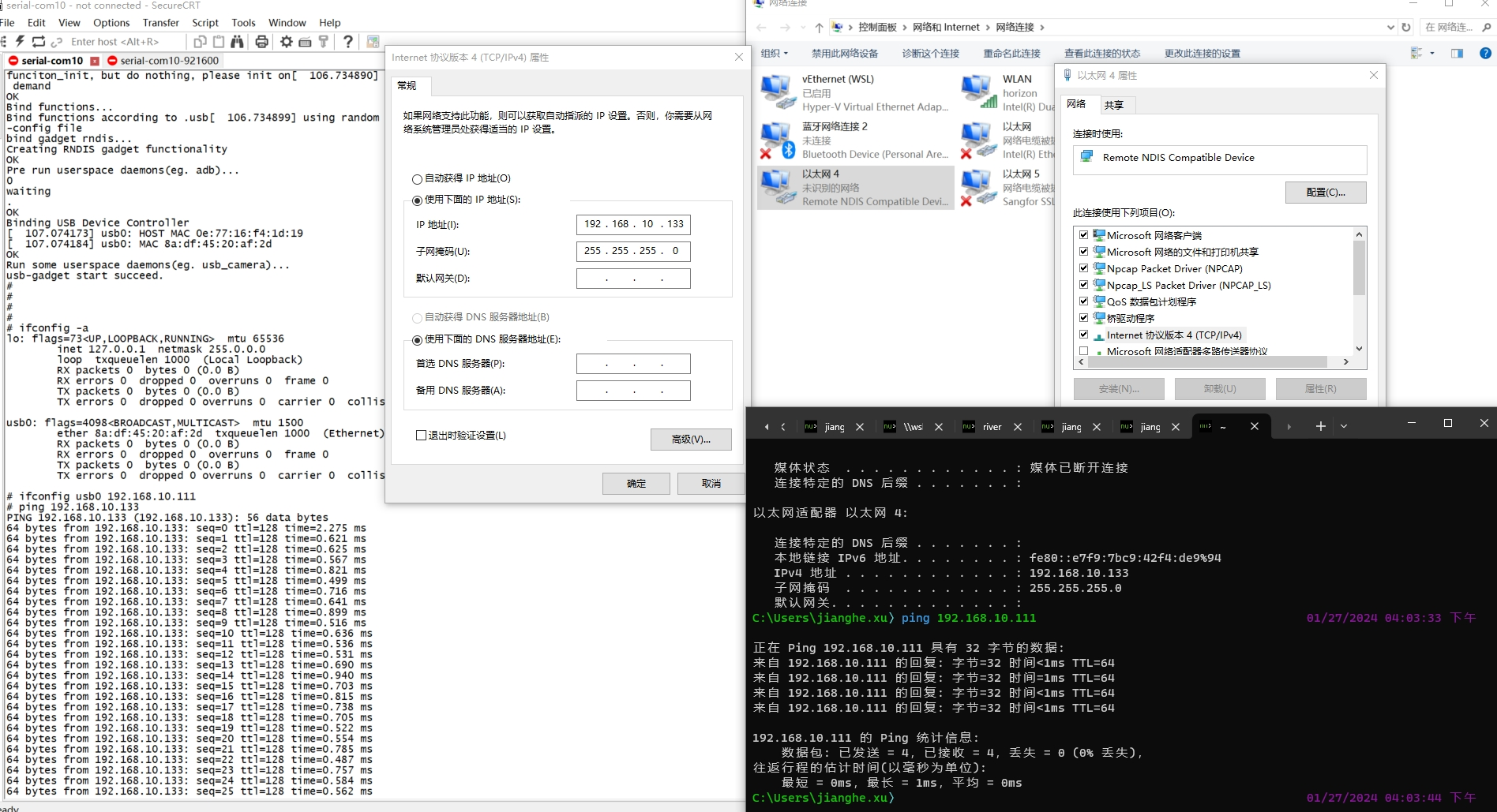
Configure the IP address of the Remote NDIS network interface on Windows, and configure the IP address of the usb0 interface on the development board, then perform a ping test. The specific steps are as follows:
Configure IP Address for Remote NDIS Interface (on PC):
Open Network Connection Settings: In Windows, right-click the network icon in the taskbar (usually Wi-Fi or Ethernet), then select
Open Network & Internet settings.Access Network Settings: In the
Network & Internetsettings window, clickChange adapter options.Locate Remote NDIS Connection: In the
Network Connectionswindow, find and right-click the Remote NDIS connection, then selectProperties.Configure IP Address: In the
Local Area Connection Propertieswindow, double-clickInternet Protocol Version 4 (TCP/IPv4)or select it and clickProperties.Manually Set IP Address: In the
Internet Protocol Version 4 (TCP/IPv4) Propertieswindow, selectUse the following IP address, then enter the IP address, subnet mask, and default gateway. Typically, you can assign an unused local network address, for example: IP address 192.168.10.133, subnet mask 255.255.255.0, and leave the gateway blank or set it to your router’s IP address.Save Configuration: After entering the details, click
OKto save and close all windows.
Configure IP Address for usb0 Interface (on Development Board):
Log in to the Development Board: Access the command line interface of the development board via serial, SSH, or other methods.
Set IP Address: Run the command
ifconfig usb0 192.168.10.111to configure the IP address of theusb0interface.
Perform Ping Test:
Verify Connection: Ensure the PC and development board are connected via USB, and both the Remote NDIS and
usb0interfaces have been correctly configured with IP addresses.Run Ping Command on PC: Open Command Prompt and enter
ping 192.168.10.111(assuming the development board’s IP is 192.168.10.111), then press Enter.Check Ping Results: If the ping command succeeds and displays responses like
Reply from 192.168.10.111, the network connection between PC and development board is functioning properly.
The configuration and test results are shown in the figure below:
2.4.3.8. Virtual Network Interface (CDC-ECM)
After the development board boots into the system, execute the following command to start ECM:
/etc/init.d/usb-gadget.sh restart ecm
Network configuration and usage can refer to Virtual Network Interface - RNDIS.
2.4.3.9. Additional Features
Run /etc/init.d/usb-gadget.sh --help to learn more features:
root@buildroot:~# /etc/init.d/usb-gadget.sh --help
USB2.0 Gadget
Detecting platform:
 board : D-Robotics X5 EVB LP4 1_B board
 udc   : 35300000.usb
Usage: /etc/init.d/usb-gadget.sh {start|stop|restart} [options]
 options:
 detail gadget-composite config, using .usb/.default-config in default
      adb                         launch adbd
      msd                         run as gadget mass storage device
      msd-ram                     run as gadget mass storage device (with DDR storage)
      hid                         run as HID gadget
      rndis                       run as RNDIS gadget
      ecm                         run as CDC Ethernet gadget
      uvc                         run as UVC gadget
      uac1                        USB Audio Class Specification 1
      uac2                        USB Audio Class Specification 2
      uvc-hid                     UVC + HID composite gadget
      uvc-uac1                    UVC + UAC1 composite gadget
      uvc-uac2                    UVC + UAC2 composite gadget
      uvc-hid-uac1                UVC + HID + UAC1 composite gadget
      uvc-hid-uac2                UVC + HID + UAC2 composite gadget
      uvc-rndis                   UVC + RNDIS composite gadget
      uvc-ecm                     UVC + CDC Ethernet composite gadget
      uvc-acm                     UVC + ACM (serial) composite gadget
      uvc-rndis-uac1              UVC + RNDIS + UAC1 composite gadget
      uvc-rndis-uac2              UVC + RNDIS + UAC2 composite gadget
      uvc-ecm-uac1                UVC + ECM + UAC1 composite gadget
      uvc-ecm-uac2                UVC + ECM + UAC2 composite gadget
      rndis-hid                   RNDIS + HID composite gadget
      rndis-uac1                  RNDIS + UAC1 composite gadget
      msd-uac1                    MSD + UAC1 composite gadget
      hid-uac1                    HID + UAC1 composite gadget
      uvc-adb                     UVC + ADB composite gadget
      rndis-adb                   RNDIS + ADB composite gadget
      hid-adb                     HID + ADB composite gadget