4.3.15. Ethernet Driver Debug Guide
4.3.15.1. Overview
In computer networking and communication, MAC (Medium Access Control) and PHY (Physical Layer) are two important concepts, involving different functions at the data link layer and physical layer respectively.
MAC (Medium Access Control) is part of the data link layer and is primarily responsible for managing data transmission over a shared communication medium. It ensures that multiple devices can effectively and coordinately share the communication channel on the same network, avoiding conflicts and interference.
Main Functions of MAC
Address Management: At the data link layer, MAC assigns a unique MAC address to each network device to identify different devices on the network.
Frame Encapsulation and Decapsulation: The MAC layer encapsulates data from upper-layer protocols into frames. At the receiving end, it decapsulates the data.
Traffic Control: By controlling the data transmission rate, it prevents network congestion and ensures stable network operation.
Collision Avoidance: In shared channels, MAC protocols must also resolve data transmission conflicts. For example, CSMA/CD protocol is used in Ethernet to detect and avoid data collisions.
Transmission Order Management: Ensures data is transmitted in the correct order, preventing packet loss and duplication.
PHY (Physical Layer) is the lowest layer in the network protocol stack, responsible for transmitting raw bitstreams over the physical medium. It handles signal transmission, reception, and conversion, and defines the electrical and mechanical characteristics of network hardware.
Main Functions of PHY
Signal Encoding and Decoding: The PHY layer converts digital data into signal formats suitable for transmission over the physical medium. The receiver decodes the signals to recover the original bitstream.
Bit Transmission: The PHY layer is responsible for sending data in bit form.
Modulation and Demodulation: In wireless communication, the PHY layer includes modulation and demodulation processes—converting digital signals into forms suitable for radio wave transmission and performing reverse operations at the receiving end.
Channel Management: The PHY layer is also responsible for physical channel selection, management, and monitoring, including parameters such as signal strength and signal-to-noise ratio (SNR), to optimize communication quality.
Terminology Explanation
| Term | Description |
|---|---|
| MAC | Medium Access Control |
| PHY | Port Physical Layer |
| MII | Media Independent Interface, a data link layer interface used to connect MAC and PHY |
| RMII | Reduced Media Independent Interface, a simplified version of the MII interface standard |
| GMII | Gigabit Media Independent Interface, a standard interface used for Gigabit Ethernet devices |
| RGMII | Reduced Gigabit Media Independent Interface, a simplified version of the traditional GMII interface |
| MDIO | Management Data Input/Output, used for management and control between MAC and PHY |
4.3.15.2. Features
X5 supports a 10/100/1000M Ethernet controller with the following features:
Supports full-duplex and half-duplex operation modes
Supports 10/100/1000 Mbps data transmission rates via RGMII interface
Supports 10/100 Mbps data transmission rates via RMII interface
Complies with IEEE 802.3-2015 Ethernet MAC standard, supports Time-Sensitive Networking (TSN) traffic
Complies with IEEE 1588-2008 standard for precise network clock synchronization
Supports TCP/UDP offload functions to reduce CPU load
4.3.15.3. Functional Description
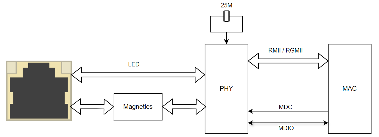
Typical Application
Typical connection diagram as shown below:
Functional Principles
MII (Media Independent Interface) is a common standard interface in Ethernet devices, used to connect the MAC layer and PHY layer. MII defines a set of signals and protocols that allow data exchange between MAC and PHY independent of the physical medium (such as cables or radio waves). This enables interaction between MAC and PHY across different physical layer technologies (e.g., 10 Mbps, 100 Mbps, 1000 Mbps Ethernet).
RMII
MII interface is commonly used in traditional Ethernet devices to connect the MAC (Medium Access Control layer) and PHY (Physical Layer). In standard MII, 20 pins are required to transmit data, clock, and control signals, which may lead to higher hardware costs in many applications. RMII was introduced to address this issue by reducing the number of signal lines, simplifying the MII interface, making hardware design more compact and cost-effective.
Main Features of RMII
Reduced Pin Count: Compared to standard MII, RMII requires only 2-bit data lines, significantly reducing connection complexity and the number of required pins, thus lowering chip and PCB costs.
Data Transfer Rate: RMII supports Ethernet transmission rates of 10 Mbps and 100 Mbps.
Clock Frequency: RMII uses a higher-frequency clock to drive data transmission. Compared to MII, RMII typically uses a 50 MHz clock, meaning two bits of data are transmitted per clock cycle.
RMII Pin Definitions
| Pin | Description | Direction |
|---|---|---|
| REF_CLK | Transmit reference clock, 50 MHz rate | Reference clock can be from an external source, MAC → PHY, or PHY → MAC |
| TXD[0:1] | Transmit data lines | MAC → PHY |
| RXD[0:1] | Receive data lines | PHY → MAC |
| TXEN | Transmit enable | MAC → PHY |
| RXER | Receive error | PHY → MAC |
| CRS/CRS_DV | Carrier sense / Receive data valid. CRS_DV must be asserted by PHY when the receive medium is not idle | PHY → MAC |
RGMII
RGMII (Reduced Gigabit Media Independent Interface) is an interface standard used in Ethernet devices to connect the MAC (Medium Access Control layer) and PHY (Physical Layer), specifically designed for Gigabit Ethernet (1 Gbps) devices. It is a simplified version of the traditional GMII (Gigabit Media Independent Interface), aiming to reduce hardware cost and complexity while maintaining support for Gigabit speeds.
Main Features of RGMII
Reduced Pin Count: Compared to traditional GMII, RGMII reduces the number of pins through simplified design
Supports Gigabit Ethernet: RGMII supports Ethernet speeds up to 1 Gbps
Clock Frequency: RGMII uses a 125 MHz clock frequency for data transmission
RGMII Pin Definitions
| Pin | Description | Direction |
|---|---|---|
| TXC | Transmit reference clock, selected as 125M / 25M / 2.5M based on PHY operating mode | MAC → PHY |
| TXD[0:3] | Transmit data lines | MAC → PHY |
| TXCTL | Transmit control | MAC → PHY |
| RXC | Receive reference clock, selected as 125M / 25M / 2.5M based on PHY operating mode | PHY → MAC |
| RXD[0:3] | Receive data lines | PHY → MAC |
| RXCTL | Receive control | PHY → MAC |
MDIO
MDIO (Management Data Input/Output) is an interface standard used for management functions in Ethernet devices. It is part of the IEEE 802.3 (Ethernet standard) and is primarily used for communication of management data between MAC (Medium Access Control layer) and PHY (Physical Layer). The MDIO interface is typically used to read and configure PHY status, speed settings, link status, etc.
Main Functions of MDIO
Link Status Monitoring: Can be used to read PHY link status, determining whether the physical link is normal or has been established.
Speed and Duplex Mode Configuration: Through the MDIO interface, MAC can set PHY operating speed (e.g., 10/100/1000 Mbps) and duplex mode (full-duplex or half-duplex).
Auto-negotiation Function: MDIO can be used to initiate or read the PHY auto-negotiation process, allowing devices to automatically select the best operating speed and mode based on network conditions.
Fault Diagnosis: MDIO can be used to diagnose PHY operational status, such as reading error counts and diagnostic information.
4.3.15.4. Driver Code
U-Boot Driver Description
Note: U-Boot currently only supports PHY operating in RGMII mode
U-Boot Device Tree
The X5 U-Boot device tree is located in the directory uboot/arch/arm/dts. Users should modify the corresponding device tree file for their project. Here we use the X5 EVB motherboard configuration file x5-soc.dtsi as an example. MAC and PHY related configurations are located in the node x5_soc_ethernet_tsn. As shown below:
x5_soc_ethernet_tsn: gmac-tsn@35010000 {
    compatible = "horizon,sunrise5-dwmac";
    status = "okay";
    reg = <0x35010000 0x10000>;
    reg-names = "stmmaceth";
    clock-names = "stmmaceth",
            "mac-clk-tx",
            "mac-clk-rx",
            "ethstp",
            "syscfg-clk";
    clocks = <&refclk>,
        <&refclk>,
        <&refclk>,
        <&refclk>,
        <&refclk>;
    phy-mode = "rgmii-id";
    phy-handle = <&x5_soc_ethphy0>;
    max-speed = <1000>;
    pinctrl-names = "default";
    pinctrl-0 = <&pinctrl_enet &pinctrl_lsio_gpio0_31_output_normal>;

    mdio {
        compatible = "snps,dwmac-mdio";
        #address-cells = <1>;
        #size-cells = <0>;

        x5_soc_ethphy0: ethernet-phy@1 {
            compatible = "ethernet-phy-ieee802.3-c22";
            reg = <1>;
            max-frequency = <125000000>;
        };
    };
};
Explanation of x5_soc_ethernet_tsn Node Properties
status: GMAC driver enable status; ensure the value isokayphy-mode: PHY operating mode; U-Boot currently only supports RGMIImax-speed: PHY operating speed; RGMII corresponds to 1000 Mbpspinctrl-0: Pin multiplexing; example usage shown:&pinctrl_enet: Multiplexed as RGMII function pins&pinctrl_lsio_gpio0_31_output_normal: PHY reset pin; here usinglsio_gpio0_31, users should adjust according to actual usage
Explanation of x5_soc_ethphy0 Node Properties
reg: PHY address; 0 means broadcast, non-zero means specific PHY addressmax-frequency: PHY clock; RGMII uses 125 MHz clock
U-Boot Driver Source Code
U-Boot GMAC driver source code is located in uboot/drivers/net/dwc_eth_qos.c
Typical Method to Add a New PHY Vendor Driver
In this example, the new vendor is named new phy; users should replace it with the actual PHY vendor name used.
Add vendor driver source code in U-Boot
U-Boot PHY vendor driver source code is located in the uboot/drivers/net/phy directory. For example, place new_phy.c into this directory.
Modify Makefile
Modifyuboot/drivers/net/phy/Makefileto add compilation entry fornew physource code:
obj-$(CONFIG_NEW_PHY) += new_phy.o
Note: Ensure CONFIG_NEW_PHY=y is set in the board-level U-Boot configuration file
Add initialization call for the new vendor
new phydriver during PHY framework initialization
Modify U-Boot source codeuboot/drivers/net/phy/phy.cto add initialization function fornew phy:
int phy_init(void)
{
...(code omitted)...
#ifdef CONFIG_NEW_PHY
	phy_new_phy_init();   // Add initialization function for vendor new phy, implemented in new_phy.c
#endif
...(code omitted)...
}
new_phy.c will implement its initialization function, example as follows:
/* Support for NEW PHY */
static struct phy_driver new_phy_driver = {
	.name = "new phy",
	.uid = 0x12ABCD,               // PHY ID corresponding to new phy network card, note: driver function is called only after matching PHY ID
	.mask = 0xffffff,              // PHY ID mask, note: PHY ID = uid & mask
	.features = PHY_GBIT_FEATURES,
	.probe = &new_phy_probe,
	.config = &new_phy_config,
	.startup = &new_phy_startup,
	.shutdown = &new_phy_shutdown,
};

int new_phy_init(void)
{
	phy_register(&new_phy_driver);

	return 0;
}
Kernel Driver Description
Note: Kernel currently supports PHY operating modes RMII and RGMII, with RGMII as default
Kernel Device Tree
The X5 kernel device tree is located in the directory kernel/arch/arm64/boot/dts/hobot. Users should modify the corresponding device tree file for their project. Here we use the X5 EVB motherboard configuration file x5-evb.dtsi as an example.
MAC and PHY related configurations are located in three nodes: gmac_tsn, hobot_tsn, and horizon_tsn, corresponding to three different drivers.
Note: Use horizon_tsn for RGMII, and gmac_tsn for RMII. When using RMII mode, the ref-clock-direction property must be specified in the device tree. This property is used to distinguish the RMII reference clock direction.
Below is an explanation using horizon_tsn as an example:
horizon_tsn: horizon_tsn@35010000 {
    compatible = "snps,dwc-qos-ethernet-5.10a";
    status = "disabled";
    reg = <0x35010000 0x10000>,
        <0x35050000 0x4>;
    interrupt-parent = <&gic>;
    interrupts = <GIC_SPI 24 IRQ_TYPE_LEVEL_HIGH>;
    interrupt-names = "mac-irq";
    clocks = <&hpsclks X5_HSIO_ENET_AXI_CLK>,
            <&hpsclks X5_HSIO_ENET_RGMII_CLK>,
            <&hpsclks X5_HSIO_ENET_PCLK>,
            <&hpsclks X5_HSIO_ENET_REF_CLK>,
            <&hpsclks X5_HSIO_ENET_PTP_REFCLK>;
    clock-names = "axi_clk", "rgmii_clk", "apb_clk",
                "ref_clk", "ptp_ref";
    resets = <&socrst HSIO_ENET_RESET>;
    reset-names = "enet_rst";

    snps,write-requests = <8>;
    snps,read-requests = <8>;
    snps,txpbl = <4>;
    snps,rxpbl = <4>;
    snps,clk_csr = <2>;
    snps,tso;
    snps,aal;
    //snps,fp;
    snps,force_sf_dma_mode = <1>;

    phy-mode = "rgmii-id";
    phy-handle = <&horizon_ethphy0>;

    mdio {
        compatible = "snps,dwmac-mdio";
        #address-cells = <1>;
        #size-cells = <0>;
        horizon_ethphy0: horizon_ethernet-phy@1 {
            compatible =
                "ethernet-phy-ieee802.3-c22";
            reg = <0>;
        };
    };
}
&horizon_tsn {
	status = "disabled";

	phy-mode = "rgmii-id";                                 // PHY operating mode is RGMII
	pinctrl-names = "default";
	pinctrl-0 = <&pinctrl_enet &hsio_gpio0_16>;            // Configure multiplexing: RGMII and reset pin
	phyreset-gpio = <&hs_gpio0_porta 16 GPIO_ACTIVE_HIGH>; // Configure reset pin; here using hsio_gpio0_16
};
Explanation of horizon_tsn Node Properties
status: GMAC driver enable status; ensure the node being used hasstatusset tookayphy-mode: PHY operating mode; currently supportsrmiiandrgmii-idpinctrl-0: Pin multiplexing; example usage shown:&pinctrl_enet: Multiplexed as RGMII function pins; usepinctrl_enet_rmiiif RMII is used&hsio_gpio0_16: PHY reset pin; here usinghsio_gpio0_16, users should adjust according to actual usage
phyreset-gpio: Reset pin; here usinghsio_gpio0_16
Explanation of x5_soc_ethphy0 Node Properties
reg: PHY address; 0 means broadcast, non-zero means specific PHY address
Note: Confirm that the PHY reset pin is configured as GPIO function. For details on GPIO multiplexing configuration, refer to GPIO Debug Guide
In RMII mode, the reference clock for MAC-PHY communication can be provided either by the MAC (MAC->PHY) or by the external PHY (PHY->MAC). Therefore, the ref-clock-direction property needs to be configured according to the hardware design.
ref-clock-direction = "tx";Reference clock is provided by MAC, clock direction is MAC->PHY.ref-clock-direction = "rx";Reference clock is provided by PHY, clock direction is PHY->MAC.
Below is an explanation using gmac_tsn as an example:
&gmac_tsn {
	status = "disabled";

	phy-mode = "rmii";              //RMII mode
    ref-clock-direction = "tx";     //Reference clock direction: MAC->PHY
	pinctrl-names = "default";
	pinctrl-0 = <&pinctrl_enet_rmii &lsio_gpio0_31>;    //RMII pin multiplexing
	phyreset-gpio = <&ls_gpio0_porta 31 GPIO_ACTIVE_HIGH>;
};
Explanation of gmac_tsn Node Properties
status: GMAC driver enable status; ensure the node being used hasstatusset tookayphy-mode: PHY operating mode isrmiiref-clock-direction: Reference clock direction configuration; needs to be set totxorrxaccording to hardware designpinctrl-0: Pin multiplexing; example usage shown:&pinctrl_enet_rmii: In RMII mode, needs to be multiplexed aspinctrl_enet_rmii&lsio_gpio0_31: PHY reset pin; here usinglsio_gpio0_31, users should adjust according to actual usage
phyreset-gpio: Reset pin; here usinglsio_gpio0_31
Kernel Driver Source Code
Kernel GMAC driver source code is located in kernel/drivers/net/ethernet/stmicro/stmmac
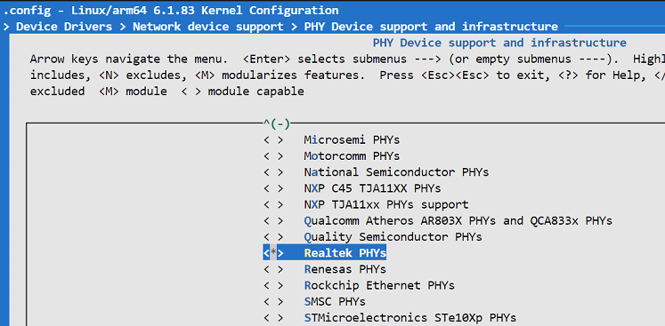
Enable PHY Driver
PHY drivers are located in the kernel/drivers/net/phy directory, containing source code for various PHY vendors. For example, enable Realtek PHY driver via menuconfig.
Match PHY ID
Taking Realtek as an example, the struct phy_driver array is a key data structure used by the kernel to register and manage multiple PHY device drivers. It is typically used to describe multiple supported PHY drivers via phy_driver and register/handle them in array form.
Take RTL8211F as an example:
static struct phy_driver realtek_drvs[] = {
{
    // ...(code omitted)...
    {
		PHY_ID_MATCH_EXACT(0x001cc916),              // PHY ID, obtainable from datasheet; driver reads registers 2 and 3
		.name		= "RTL8211F Gigabit Ethernet",   // Driver name
		.probe		= rtl821x_probe,
		.config_init	= &rtl8211f_config_init,
		.read_status	= rtlgen_read_status,
		.config_intr	= &rtl8211f_config_intr,
		.handle_interrupt = rtl8211f_handle_interrupt,
		.suspend	= genphy_suspend,
		.resume		= rtl821x_resume,
		.read_page	= rtl821x_read_page,
		.write_page	= rtl821x_write_page,
	},
    // ...(code omitted)...
}
When the driver matches the PHY ID, the following log will appear:
[    5.684946] hobot_gmac 35010000.horizon_tsn eth0: PHY [hobot-mac-mdio-35010000:00] driver [RTL8211F Gigabit Ethernet] (irq=POLL)
[    5.705015] hobot_gmac 35010000.horizon_tsn eth0: mac_config_rx_queues_routing, not support packet mode :
[    5.714742] hobot_gmac 35010000.horizon_tsn eth0: configuring for phy/rgmii-id link mode
PHY Driver Matching Check
The kernel can check the matched PHY driver via sysfs. Procedure as follows:
View System-Supported PHY Drivers
Currently supported PHY drivers are located under /sys/bus/mdio_bus/drivers, existing as subdirectories.
root@buildroot:/sys/bus/mdio_bus/drivers# ls -al
total 0
drwxr-xr-x 24 root root 0 Jan  1 00:00  .
drwxr-xr-x  4 root root 0 Jan  1 00:00  ..
drwxr-xr-x  2 root root 0 Jan  1 00:00 'Generic Clause 45 PHY'
drwxr-xr-x  2 root root 0 Jan  1 00:00 'Generic FE-GE Realtek PHY'
drwxr-xr-x  2 root root 0 Jan  1 00:00 'Generic PHY'
drwxr-xr-x  2 root root 0 Jan  1 00:00 'RTL8201CP Ethernet'
drwxr-xr-x  2 root root 0 Jan  1 00:00 'RTL8201F Fast Ethernet'
drwxr-xr-x  2 root root 0 Jan  1 00:00 'RTL8208 Fast Ethernet'
drwxr-xr-x  2 root root 0 Jan  1 00:00 'RTL8211 Gigabit Ethernet'
drwxr-xr-x  2 root root 0 Jan  1 00:00 'RTL8211B Gigabit Ethernet'
drwxr-xr-x  2 root root 0 Jan  1 00:00 'RTL8211C Gigabit Ethernet'
drwxr-xr-x  2 root root 0 Jan  1 00:00 'RTL8211DN Gigabit Ethernet'
drwxr-xr-x  2 root root 0 Jan  1 00:00 'RTL8211E Gigabit Ethernet'
drwxr-xr-x  2 root root 0 Jan  1 00:00 'RTL8211F Gigabit Ethernet'
drwxr-xr-x  2 root root 0 Jan  1 00:00 'RTL8211F-VD Gigabit Ethernet'
drwxr-xr-x  2 root root 0 Jan  1 00:00 'RTL8221B-VB-CG 2.5Gbps PHY'
drwxr-xr-x  2 root root 0 Jan  1 00:00 'RTL8221B-VM-CG 2.5Gbps PHY'
drwxr-xr-x  2 root root 0 Jan  1 00:00 'RTL8226 2.5Gbps PHY'
drwxr-xr-x  2 root root 0 Jan  1 00:00 'RTL8226-CG 2.5Gbps PHY'
drwxr-xr-x  2 root root 0 Jan  1 00:00 'RTL8226B-CG_RTL8221B-CG 2.5Gbps PHY'
drwxr-xr-x  2 root root 0 Jan  1 00:00 'RTL8226B_RTL8221B 2.5Gbps PHY'
drwxr-xr-x  2 root root 0 Jan  1 00:00 'RTL8365MB-VC Gigabit Ethernet'
drwxr-xr-x  2 root root 0 Jan  1 00:00 'RTL8366RB Gigabit Ethernet'
drwxr-xr-x  2 root root 0 Jan  1 00:00 'RTL9000AA_RTL9000AN Ethernet'
View System-Matched PHY Driver
The X5 system GMAC driver is located at /sys/bus/mdio_bus/devices/hobot-mac-mdio-35010000:00, also existing as a directory. The driver directory is a symbolic link pointing to the currently matched PHY driver, as shown below:
root@buildroot:/sys/bus/mdio_bus/devices/hobot-mac-mdio-35010000:00# ls
attached_dev  driver  of_node  phy_dev_flags  phy_has_fixups  phy_id  phy_interface  power  statistics  subsystem  uevent
root@buildroot:/sys/bus/mdio_bus/devices/hobot-mac-mdio-35010000:00# ls -al driver/hobot-mac-mdio-35010000\:00/driver
lrwxrwxrwx 1 root root 0 Jan  1 00:04 driver/hobot-mac-mdio-35010000:00/driver -> '../../../../../../../../bus/mdio_bus/drivers/RTL8211F Gigabit Ethernet'
It can be seen that the driver points to /sys/bus/mdio_bus/drivers/RTL8211F Gigabit Ethernet, indicating that the currently matched PHY driver is RTL8211F.
4.3.15.5. Usage
U-Boot Usage
U-Boot Set Static IP
Set X5 U-Boot to static IP:
Hobot>setenv ipaddr 192.168.1.10
U-Boot Dynamic IP Acquisition
Connect the X5 Ethernet port to a router or DHCP server. After entering U-Boot, set the DHCP server IP and use the dhcp command to obtain an IP dynamically, as shown below:
Hobot>setenv serverip 192.168.1.1
Hobot>setenv autoload no
Hobot>dhcp
U-Boot Verify PHY Connectivity
In U-Boot, use the ping command to verify connectivity. First set the local IP address:
Hobot>setenv ipaddr 192.168.1.10
Hobot>ping 192.168.1.11
gmac-tsn@35010000 Waiting for PHY auto negotiation to complete..... done
Using gmac-tsn@35010000 device
host 192.168.1.11 is alive
If host 192.168.1.11 is alive appears, the network is functioning properly.
U-Boot Read/Write PHY Registers
In U-Boot, use the mii command set to read/write PHY registers.
View Current MII Device List
Hobot>mii device
MII devices: 'gmac-tsn@35010000'
Current device: 'gmac-tsn@35010000'
Shows the currently available and selected MII device in U-Boot is gmac-tsn@35010000.
Read PHY Register Value and Display Bit-Level Status
Format: mii dump <addr> <reg>, parameter descriptions:
addr: PHY addressreg: Register address, only supports [0:5]
Note: Recommended for reading PHY standard registers, as it clearly displays each bit status
Example: Read register 0 status
Hobot>mii dump 1 0
0.     (1040)                 -- PHY control register --
  (8000:0000) 0.15    =     0     reset
  (4000:0000) 0.14    =     0     loopback
  (2040:0040) 0. 6,13 =   b10    speed selection = 1000 Mbps
  (1000:1000) 0.12    =     1     A/N enable
  (0800:0000) 0.11    =     0     power-down
  (0400:0000) 0.10    =     0     isolate
  (0200:0000) 0. 9    =     0     restart A/N
  (0100:0000) 0. 8    =     0     duplex = half
  (0080:0000) 0. 7    =     0     collision test enable
  (003f:0000) 0. 5- 0 =     0     (reserved)
Read PHY Register Value
Format: mii read <addr> <reg>
Note: Can be used to read all PHY register values, including standard and custom registers
Example: Read register 0 value
Hobot>mii read 1 0
1040
Kernel Usage
Set IP Parameters
Linux network interface IP parameters are configured via the file /etc/network/interfaces.
Set Static IP
Configuration example for setting eth0 to static IP:
auto eth0
iface eth0 inet static          # Set eth0 to static IP
    address 192.168.1.10        # Set static IP address
    netmask 255.255.255.0       # Set subnet mask
    gateway 192.168.1.1         # Set gateway address
    broadcast 192.168.1.255     # Set broadcast address
    metric 700                  # Set metric value
Set Dynamic IP
Configuration example for eth0 to obtain IP dynamically via DHCP:
auto eth0
iface eth0 inet dhcp
Common System Commands
View Network Interface Status
ls /sys/class/net
Each network interface exists as a subdirectory under /sys/class/net. Each directory contains configurable parameter files. Users can configure or view network interface status via nodes in this directory.
Common configuration files:
| Parameter File | Description |
|---|---|
| address | MAC address |
| broadcast | Broadcast address |
| carrier | Physical connection status, 1 means connected, 0 means disconnected |
| carrier_changes | Number of times network interface connection status changes are recorded |
| dev_id | Unique identifier for the network interface device in the system |
| duplex | Displays the network interface working mode; full indicates full-duplex, half indicates half-duplex |
| mtu | Maximum Transmission Unit, in bytes |
| speed | Network interface speed, in Mbps |
| tx_queue_len | Transmission queue length of the network interface; adjusting this value can affect transmission performance under high network load |
| statistics | Detailed statistics of the network interface, used for diagnosing network issues |
Enable/Disable eth0
ifconfig eth0 up         # Enable eth0
ifconfig eth0 down       # Disable eth0
Configure eth0 Parameters
ifconfig eth0 192.168.1.10                  # Set static IP
ifconfig eth0 hw ether 00:11:22:aa:bb:cc    # Set MAC address
ifconfig eth0 netmask 255.255.255.0         # Set subnet mask
route add default gw 192.168.1.1            # Add gateway
ethtool
ethtool is a command-line tool used to query and configure network interface parameters. It allows users to view the configuration, operational status, and supported features of a network interface, and to modify certain settings such as network speed, duplex mode, and enabling/disabling specific features. ethtool is a powerful tool widely used by network administrators and developers for managing and debugging network devices.
View Network Interface Status
Below is an example using eth0, with explanations of the output fields:
# ethtool eth0
Settings for eth0:
        Supported ports: [ TP MII ]
        Supported link modes:   10baseT/Full                  # Link modes supported by the NIC
                                100baseT/Full
                                1000baseT/Full
        Supported pause frame use: Symmetric Receive-only
        Supports auto-negotiation: Yes                        # Auto-negotiation supported
        Supported FEC modes: Not reported
        Advertised link modes:  10baseT/Full                  # Advertised link modes
                                100baseT/Full
                                1000baseT/Full
        Advertised pause frame use: Symmetric Receive-only
        Advertised auto-negotiation: Yes                      # Auto-negotiation enabled
        Advertised FEC modes: Not reported
        Link partner advertised link modes:  10baseT/Half 10baseT/Full
                                             100baseT/Half 100baseT/Full
                                             1000baseT/Full
        Link partner advertised pause frame use: Symmetric Receive-only
        Link partner advertised auto-negotiation: Yes
        Link partner advertised FEC modes: Not reported
        Speed: 1000Mb/s                # Current NIC speed
        Duplex: Full                   # NIC working mode
        Port: Twisted Pair
        PHYAD: 0                       # PHY address
        Transceiver: external
        Auto-negotiation: on
        MDI-X: Unknown
        Supports Wake-on: ug
        Wake-on: d
        Link detected: yes
Network Interface Statistics
ethtool -S eth0 displays detailed network interface statistics, such as received bytes, transmitted bytes, packet drops, and error counts. This helps network administrators diagnose network performance, errors, and traffic issues. Commonly used statistics include:
Receive Statistics
rx_packets: Total number of received packets.
rx_bytes: Total number of received bytes.
rx_errors: Number of errors occurred during reception, such as CRC errors or frame errors.
rx_dropped: Number of received packets dropped, possibly due to buffer overflow or other reasons.
rx_fifo_errors: Number of FIFO queue overflow errors on the receiver side, indicating the receive FIFO is full and packets cannot be processed.
rx_length_errors: Number of received packets with length errors (e.g., exceeding maximum length).
rx_crc_errors: Number of CRC errors during reception, indicating data corruption during transmission.
Transmit Statistics
tx_packets: Total number of transmitted packets.
tx_bytes: Total number of transmitted bytes.
tx_errors: Number of errors occurred during transmission, such as checksum errors or device errors.
tx_dropped: Number of transmitted packets dropped, typically under network congestion or insufficient device resources.
tx_fifo_errors: Number of FIFO queue overflow errors on the transmitter side, indicating the transmit FIFO is full and packets cannot be sent.
tx_collisions: Number of collisions (only possible in half-duplex Ethernet mode).
tx_carrier_errors: Number of carrier errors, usually related to physical layer link issues.
Set Network Interface Speed and Duplex Mode
Set the network interface speed to 1000Mbps and enable full-duplex mode:
ethtool -s eth0 speed 1000 duplex full autoneg off
Network Interface Speed Testing
U-Boot does not have a complete protocol stack, so speed/mode testing is recommended under the kernel.
Note: Speed testing requires switching the network interface to different modes. You can adjust the peer device’s speed and reach the target speed/mode via negotiation, or force a specific speed/mode using ethtool, then perform speed testing with iperf.
Below is a speed test using 1000M full-duplex mode.
Set the network interface speed to 1000Mbps and enable full-duplex:
ethtool -s eth0 speed 1000 duplex full autoneg off
On the PC, start iperf3 as a server waiting for the board to connect:
> .\iperf3.exe -s
-----------------------------------------------------------
Server listening on 5201 (test #1)
-----------------------------------------------------------
On the board, act as a client to perform the speed test:
# iperf3 -p 5201 -c 192.168.1.11
Connecting to host 192.168.1.11, port 5201
[  5] local 192.168.1.10 port 52942 connected to 192.168.1.11 port 5201
[ ID] Interval           Transfer     Bitrate         Retr  Cwnd
[  5]   0.00-1.00   sec   114 MBytes   956 Mbits/sec    0    345 KBytes
[  5]   1.00-2.00   sec   113 MBytes   950 Mbits/sec    0    345 KBytes
[  5]   2.00-3.00   sec   113 MBytes   947 Mbits/sec    0    345 KBytes
[  5]   3.00-4.00   sec   113 MBytes   949 Mbits/sec    0    345 KBytes
[  5]   4.00-5.00   sec   113 MBytes   950 Mbits/sec    0    345 KBytes
[  5]   5.00-6.00   sec   113 MBytes   949 Mbits/sec    0    345 KBytes
[  5]   6.00-7.00   sec   113 MBytes   950 Mbits/sec    0    345 KBytes
[  5]   7.00-8.00   sec   113 MBytes   951 Mbits/sec    0    345 KBytes
[  5]   8.00-9.00   sec   113 MBytes   947 Mbits/sec    0    345 KBytes
The speed meets the requirement.
Note: For other modes/speeds, please refer to the above method; details are omitted here.
4.3.15.6. Common Issues
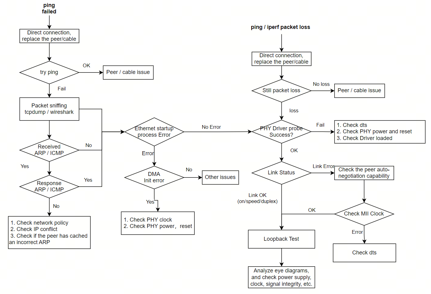
Quick Network Interface Troubleshooting
PHY-related network issues are mainly categorized as no network connectivity or severe packet loss. Refer to the following methods for quick checks:
“Cannot attach to PHY” When Loading Network Interface
Error message:
root@ubuntu:~# ifconfig eth0 up
[  222.582785] dwc-eth-dwmac 35010000.gmac-tsn eth0: __stmmac_open: Cannot attach to PHY (error: -19)
SIOCSIFFLAGS: No such device
MDIO communication failure on the network interface. Troubleshoot using the following steps:
Check if the network interface power supply is normal
Verify whether the reset pin is multiplexed as GPIO and whether the reset timing meets the datasheet requirements; typically, the PHY requires the reset pin to be held low for a certain duration to ensure valid reset
Check if MDIO communication is abnormal, e.g., check for signal waveforms and whether the MDC clock rate is within specification (usually no more than 2.5MHz)
“MAC Reset Failed”
U-Boot logs show:
EQOS_DMA_MODE_SWR stuck
Kernel reports “DMA engine initialization failed” when link comes up:
Error message: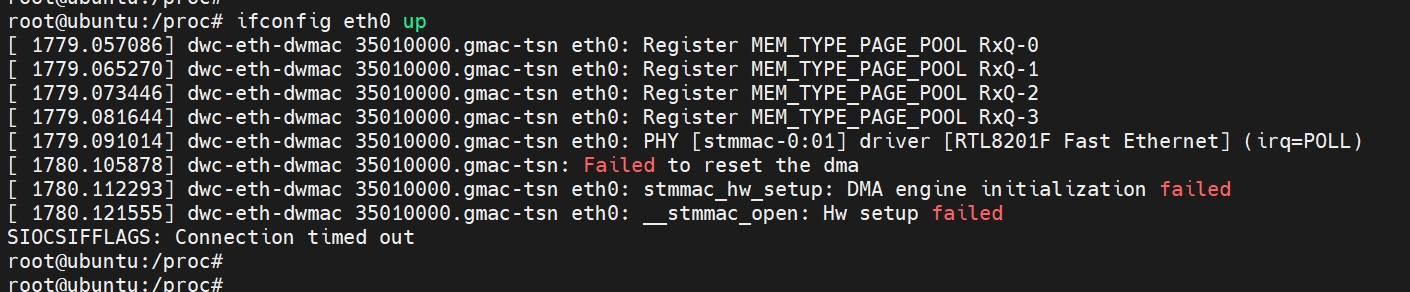
Root cause analysis: Usually due to MAC reset failure, commonly caused by missing RGMII-RX clock. Analyze using the following steps:
Check if a reference clock is present and whether its frequency and amplitude meet requirements
Verify PHY power supply and reset pin status
Review PHY datasheet for any special register configuration required before RGMII-RX clock is provided
Auto-negotiation Failure
Troubleshooting methods:
Use cross-comparison to determine whether the issue is on the local or peer side
If negotiation fails in U-Boot, try increasing the timeout to see if it improves
Use
ethtool eth0to check whether the PHY negotiation capabilities of both local and peer devices match expectations, and whether either side restricts auto-negotiation
Unable to Ping in U-Boot / Kernel
Use third-party devices and cables for cross-validation to rule out peer device or cable issues; direct connection testing (without routers or switches) is preferred
In U-Boot, verify correct
ipaddrsetting, ensure it is in the same subnet as the peer, and avoid IP address conflictsIn kernel, verify correct IP address and subnet mask configuration, ensure same subnet as peer, and avoid IP conflicts
Perform packet capture on the peer device:
If ARP packets from the board are received but no ARP reply is sent, check for IP conflicts
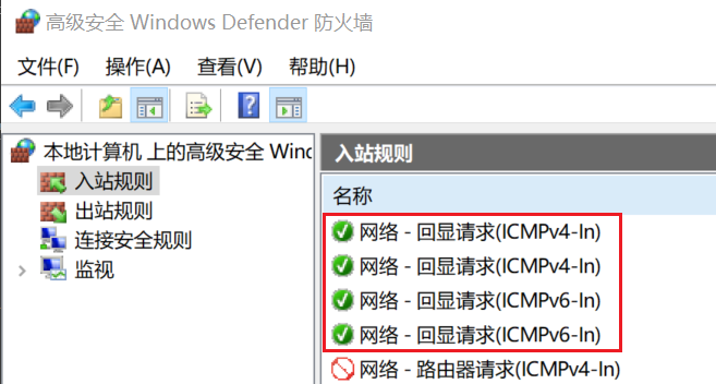
If ARP exchange is normal and ICMP packets are received but no ICMP reply is sent, investigate peer network policies. For example, ensure Windows firewall is disabled and ICMP inbound rules are enabled.
Severe Packet Loss or High Number of Transmit/Receive Errors
Troubleshooting methods:
Perform eye diagram testing to verify signal quality meets requirements.
Confirm whether clock delay is enabled on the PHY.
Measure clock stability.
Use
ethtool -S eth0 | grep crcto count packets dropped due to CRC errors. If this value increases significantly over time, it is likely a signal integrity issue.