4.3.21. Wi-Fi Driver Debug Guide
4.3.21.1. Overview
This chapter mainly describes the adaptation and usage methods of Wi-Fi, using the RealTek (RTL) series SDIO WiFi RTL8852BS and Quectel’s FCS960K as examples.
Main content includes: schematic confirmation, source code addition, kernel configuration, DTS configuration, driver loading and debugging, Wi-Fi usage, and common issues.
4.3.21.2. RealTek RTL8852BS Porting
The X5 EVB V1 development board uses the RTL8852BS module, supporting Wi-Fi and Bluetooth functions.
Wi-Fi uses the SDIO interface, supports 2.4G and 5G frequency bands, and complies with IEEE802.11a/b/g/n/ac/axWLAN standards.
The X5 system automatically loads the Wi-Fi driver during boot.
For debugging the Bluetooth function of the RTL8852BS module, refer to the Bluetooth Driver Debug Guide.
Schematic Confirmation
Partial schematics of X5 RTL8852BS are shown below:
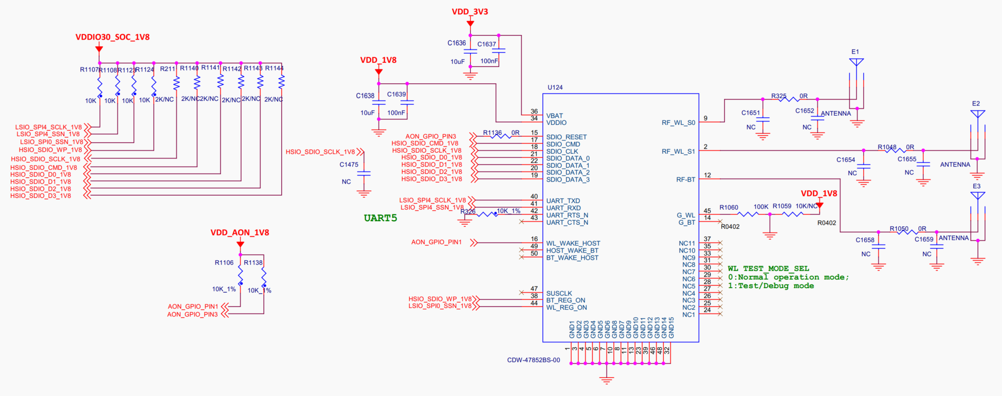
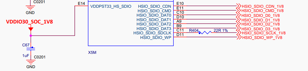
For the RTL8852BS Wi-Fi module to operate properly, the hardware must meet the following conditions:
Power supply: The module has two power supplies:
VDD_3V3as the main power andVDD_1V8as the IO pull-up power.Enable: To work normally, both
WL_REG_ONandSDIO_RESETmust be set to high level. Currently, these signals are pulled up at power-on in hardware, so no configuration is needed in the device tree.Clock: The 40MHz clock can be internally generated by the module; no external input is required.
Communication: Communication between the module and SOC is via SDIO, where
SDIO_DATA_0,SDIO_DATA_1,SDIO_DATA_2, andSDIO_DATA_3are the four data lines of SDIO.SDIO_CMDandSDIO_CLKare the command and clock lines, respectively.
Adding Source Code
Step 1: Obtain Driver Source Code
The X5 Kernel version is 6.1.83; it is recommended to use the vendor-provided driver adapted for this kernel version.
Step 2: Create Driver Directory
Create a
rtl8852bsdirectory underkernel/drivers/stagingand copy the driver source code.Step 3: Configure Kconfig and Makefile
Add the following content to
kernel/drivers/staging/Kconfig:source "drivers/staging/rtl8852bs/Kconfig"
Add compilation support in
kernel/drivers/staging/Makefile:obj-$(CONFIG_RTL8852BS) += rtl8852bs/
Step 4: Adjust Kconfig Configuration
In
kernel/drivers/staging/rtl8852bs/Kconfig, correct the help message syntax parsing:config RTL8852BS tristate "Realtek 8852B SDIO WiFi" - ---help--- + help Help message of RTL8852BS
In
kernel/drivers/staging/rtl8852bs/Makefile, modify platform-related configurations:###################### Platform Related ####################### -CONFIG_PLATFORM_I386_PC = y +CONFIG_PLATFORM_I386_PC = n +CONFIG_PLATFORM_ARM_HOBOT = y ########### CUSTOMER ################################ CONFIG_DRVEXT_MODULE = n @@ -240,6 +240,8 @@ endif ifeq ($(CONFIG_PLATFORM_RTL8198D), y) DRV_PATH = $(src) +else ifeq ($(CONFIG_PLATFORM_ARM_HOBOT), y) +DRV_PATH = $(srctree)/$(src) else DRV_PATH = $(TopDIR) endif
Step 5: Create New Platform Compilation Options
According to the RealTek porting document, create a new file
kernel/drivers/staging/rtl8852bs/platform/arm_hb.mkand add HOBOT platform configuration compilation options:ifeq ($(CONFIG_PLATFORM_ARM_HOBOT), y) EXTRA_CFLAGS += -DCONFIG_PLATFORM_ARM_HOBOT EXTRA_CFLAGS += -DCONFIG_LITTLE_ENDIAN EXTRA_CFLAGS += -DCONFIG_IOCTL_CFG80211 -DRTW_USE_CFG80211_STA_EVENT EXTRA_CFLAGS += -DCONFIG_RADIO_WORK EXTRA_CFLAGS += -DCONFIG_CONCURRENT_MODE ifeq ($(CONFIG_PCI_HCI), y) EXTRA_CFLAGS += -DCONFIG_PLATFORM_OPS _PLATFORM_FILES := platform/platform_linux_HB_pci.o \ platform/platform_ARM_HB_pci.o OBJS += $(_PLATFORM_FILES) # Core Config # CONFIG_RTKM - n/m/y for not support / standalone / built-in CONFIG_RTKM = m EXTRA_CFLAGS += -DCONFIG_TX_SKB_ORPHAN # PHL Config EXTRA_CFLAGS += -DRTW_WKARD_98D_RXTAG endif ifeq ($(CONFIG_SDIO_HCI), y) _PLATFORM_FILES = platform/platform_ARM_HB_sdio.o endif endif # CONFIG_PLATFORM_ARM_HOBOT
Then execute
./bd.sh boot menuconfigto check if the rtl8852bs module appears, select it, and resolve any compilation errors.
Function Testing and Debugging
WIFI module driver log configuration method is as follows, in Makefile:
During debugging, it is recommended to set
CONFIG_RTW_DEBUG = y. After debugging, setCONFIG_RTW_DEBUG = n.CONFIG_RTW_LOG_LEVELcan be set to 2 or 4.When set to 2, only error messages are output.
When set to 4, warning, debug, and error messages are all output.
CONFIG_RTW_DEBUG = n     #debug switch
CONFIG_RTW_LOG_LEVEL = 4 #debug level
Kernel Configuration
Enter the build directory of the BSP and run ./xbuild.sh boot menuconfig to configure kernel features.
Configuration Command
Running ./xbuild.sh boot menuconfig launches a text-based menu interface. Use keyboard arrow keys to navigate the menu. Press Enter to enter submenus or modify configuration options. After completing the configuration, choose the “Save” menu item to save your settings.
Configuration Options
Option 1: Configure kernel option CONFIG_RTL8852BS=m

Option 2: Configure kernel option CONFIG_CFG80211=m
WiFi usage requires enabling cfg80211 and mac80211 support in the kernel.

Option 3: Configure kernel option CONFIG_RFKILL=m

DTS Configuration
Controller Confirmation
There are three MMC controllers on the X5. First, confirm which controller the RTL8852BS uses, as follows:
Based on the schematic connection and device tree
pinmux-func.dtsi, the pinHSIO_SDIO_CMDcorresponds to the multiplexing configurationpinctrl_sdio.pinctrl_sdio: sdiogrp { horizon,pins = < HSIO_SDIO_WP HSIO_PINMUX_2 BIT_OFFSET8 MUX_ALT0 &pconf_sd_sdio_pu_ds3_ipctrl HSIO_SDIO_CLK HSIO_PINMUX_0 BIT_OFFSET30 MUX_ALT0 &pconf_sd_sdio_pu_ds5_ipctrl HSIO_SDIO_CMD HSIO_PINMUX_0 BIT_OFFSET28 MUX_ALT0 &pconf_sd_sdio_pu_ds3_ipctrl HSIO_SDIO_DATA0 HSIO_PINMUX_1 BIT_OFFSET0 MUX_ALT0 &pconf_sd_sdio_pu_ds3_ipctrl HSIO_SDIO_DATA1 HSIO_PINMUX_2 BIT_OFFSET30 MUX_ALT0 &pconf_sd_sdio_pu_ds3_ipctrl HSIO_SDIO_DATA2 HSIO_PINMUX_2 BIT_OFFSET28 MUX_ALT0 &pconf_sd_sdio_pu_ds3_ipctrl HSIO_SDIO_DATA3 HSIO_PINMUX_2 BIT_OFFSET26 MUX_ALT0 &pconf_sd_sdio_pu_ds3_ipctrl >; };
The
pinctrl_sdioconfiguration is referenced by thesdio_1node in the board-level device tree./* SDIO */ &sdio_1 { status = "okay"; pinctrl-names = "default"; pinctrl-0 = <&pinctrl_sdio>; };
Further checking the
sdio_1node configuration in thex5.dtsifile confirms that the controller used issdhci@35030000.sdio_1: sdhci@35030000 { compatible = "horizon,x5-dwcmshc-sd"; status = "disabled"; reg = <0x35030000 0x10000>, <0x3505008c 0x10>; /* ctrler, dll_ctrl */ interrupt-parent = <&gic>; interrupts = <GIC_SPI 15 IRQ_TYPE_LEVEL_HIGH>; max-frequency = <200000000>; clocks = <&hpsclks X5_HSIO_SDIO1_BCLK>, <&hpsclks X5_HSIO_SDIO1_HCLK>, <&hpsclks X5_HSIO_SDIO1_ACLK>, <&hpsclks X5_HSIO_SDIO1_CCLK>, <&hpsclks X5_HSIO_SDIO1_TCLK>; clock-names = "core", "bus", "axi", "card", "timer"; bus-width = <4>; non-removable; no-sd; no-mmc; cap-sdio-irq; cap-sd-highspeed; sd-uhs-sdr50; sd-uhs-sdr104; mmc-fixed-voltage = <1800>; disable-wp; resets = <&socrst HSIO_SDIO_RESET>; reset-names = "sd_rst"; };
Confirm DTS Configuration
For explanation of DTS configuration parsing, see Peripheral Adaptation Notes.
Confirm that the
sdio_1node hasstatus = "okay".On the X5 EVB, the WIFI RTL8852BS powers on with the system. By default, the device tree uses the
non-removableconfiguration. According to the hardware design, if manual control of the power-up sequence is required, thenon-removablesetting can be removed.
The actual sdio node configuration used in x5-evb.dtsi:
```dts
/* SDIO */
&sdio_1 {
	status = "okay";
	pinctrl-names = "default";
	pinctrl-0 = <&pinctrl_sdio>;
};
```
Build and Flash
After saving the configuration, recompile the kernel image using
./mk_boot.sh, then flashboot.imgusingfastboot.exe flash boot boot.img.Then use adb to upload
rfkill.ko,cfg80211.ko, and8852bs.koto the file system. For adb usage, refer to Using adb.
Driver Loading and Debugging
Use an oscilloscope to measure whether power, enable, and clock meet requirements; coordinate with hardware for verification.
After entering the system, use the following command to confirm that the device tree sdio node configuration takes effect; output should be
okay.#cat /sys/firmware/devicetree/base/soc/hsio_apb/sdhci@35030000/status okayAfter SDIO controller initialization, use the following command to view the correspondence between the SDIO controller and the mmc index.
#ls /sys/devices/platform/soc/35000000.hsio_apb/35030000.sdhci/mmc_host
mmc2
Use the following command to check if the SDIO controller’s configuration and runtime parameters are correct.
#cat /sys/kernel/debug/mmc2/ios
clock:          200000000 Hz
actual clock:   200000000 Hz
vdd:            21 (3.3 ~ 3.4 V)
bus mode:       2 (push-pull)
chip select:    0 (don't care)
power mode:     2 (on)
bus width:      2 (4 bits)
timing spec:    6 (sd uhs SDR104)
signal voltage: 1 (1.80 V)
driver type:    0 (driver type B)
Use
insmodto load the required Wi-Fi drivers separately.Use
insmod rfkill.koto load the wireless device management module.Use
insmod cfg80211.koto load the wireless device configuration interface module.Use
insmod 8852bs.koto load the RTL8852bs driver module.
When loading the driver, the SDIO controller attempts to communicate with the attached device. If communication fails, check the device tree configuration and debug using Ftrace. For details, refer to the Ftrace Usage Guide.
After successful driver loading and communication, use
ifconfig wlan0to check if the wlan0 network interface is created.wlan0: flags=4098<BROADCAST,MULTICAST> mtu 1500 ether 5c:8a:ae:34:db:ec txqueuelen 1000 (Ethernet) RX packets 0 bytes 0 (0.0 B) RX errors 0 dropped 0 overruns 0 frame 0 TX packets 0 bytes 0 (0.0 B) TX errors 0 dropped 0 overruns 0 carrier 0 collisions 0
RTL8852BS WOW Feature Verification
WOW (Wake on WLAN) is a technology that allows a device in sleep mode to be awakened by receiving specific packets via Wi-Fi. WOW technology uses a “hardware monitoring + signal assertion” mechanism to achieve remote network wake-up while maintaining extremely low standby power consumption. The core principle is that the Wi-Fi chip retains packet parsing capability in sleep mode; once a preset pattern is matched, it immediately triggers a host interrupt via a physical signal. The Out-band wake-up method uses a dedicated GPIO pin for waking up, connecting the Wi-Fi chip’s GPIO directly to the host’s wake-up input pin. When the chip detects a wake-up packet, it sends a pulse signal through the GPIO to wake the host.
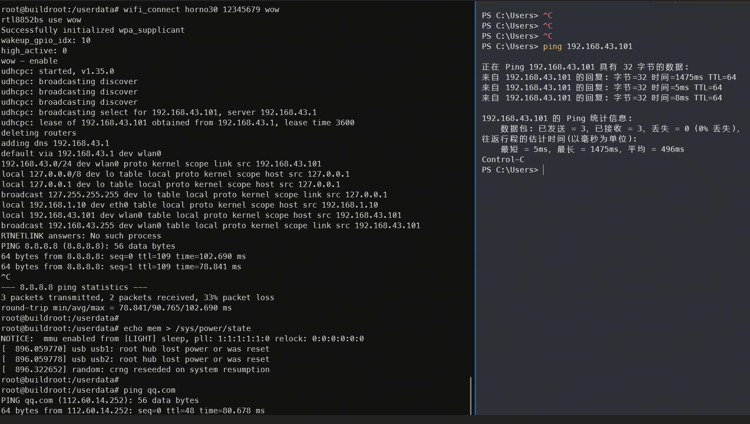
Use the script
wifi_connect "ssid" "password" wowto start the script.Run
echo mem > /sys/power/stateto put X5 into deep sleep mode.Ping the board’s IP address; a magic packet will be sent to the module to wake up the host.
Run
ping qq.comon the board to verify successful wake-up; the board should still be on the network.
4.3.21.3. FCS960K Porting
The X5 EVB V2 development board uses the FCS960K module, supporting Wi-Fi and Bluetooth functions.
Wi-Fi uses the SDIO interface, supports 2.4G and 5G frequency bands, and complies with IEEE802.11a/b/g/n/ac/axWLAN standards.
The X5 system automatically loads the Wi-Fi driver during boot.
For debugging the Bluetooth function of the FCS960K module, refer to the Bluetooth Driver Debug Guide.
Schematic Confirmation
Partial schematics of X5 FCS960K are shown below:
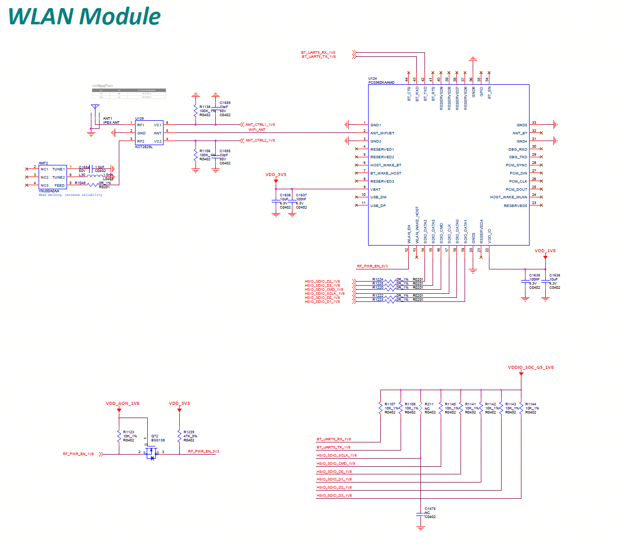
For FCS960K to operate properly, the following hardware conditions must be met:
Power supply: The module has two power supplies:
VDD_3V3as the main power andVDD_1V8as the IO pull-up power.Enable: To work normally,
RF_PWR_ENmust be set to high level.Antenna: WIFI/Bluetooth antenna interface
ANT_WIFI/BT. The EVB provides both onboard and external antenna switching, supporting free switching.Communication Interface Configuration
Wi-Fi Subsystem (SDIO Interface)
SDIO_DATA_0,SDIO_DATA_1,SDIO_DATA_2,SDIO_DATA_3are the four data lines of SDIO.SDIO_CMDandSDIO_CLKare the command and clock lines, respectively.
Bluetooth Subsystem (Multi-mode Expandable Interface)
Basic Communication Mode (UART Only)
Interface pins:
BT_RX,BT_TXFeatures: Asynchronous serial data communication based on UART (e.g., AT command interaction, low-speed data transmission), without flow control. Risk of packet loss and buffer overflow under baud rate overload or sustained large data transmission.
Enhanced Transmission Mode (with Hardware Flow Control)
Interface pins:
BT_RX,BT_TX,BT_CTS,BT_RTSFeatures: Effectively avoids packet loss and buffer overflow, supports high-fidelity unidirectional audio streaming such as A2DP.
Voice Communication Mode (PCM Synchronous Interface)
Interface pins:
PCM_SYNC,PCM_DIN,PCM_CLK,PCM_DOUTFeatures: Supports real-time bidirectional audio transmission over SCO links, such as HFP/HSP.
Note
To fully utilize the EVB’s expansion capabilities, the current hardware design integrates various interfaces and peripherals. Due to interface layout and hardware resource constraints, the EVB does not fully replicate all communication interfaces of the Bluetooth module.
If your project requires full Bluetooth protocol stack functionality (e.g., PCM audio transmission, hardware flow control), it is recommended to contact the Bluetooth module supplier directly for customized selection advice, interface expansion solutions, and deep firmware support.
Driver Porting
The X5 EVB V2 has completed the FCS960K Wi-Fi module porting. You can directly use Wi-Fi and Bluetooth starting from version V1.0.20 and later.
If you have customization or development needs, you can read the following sections to understand the detailed porting process.
Adding Source Code
Step 1: Obtain Driver Source Code
The X5 Kernel version is 6.1.83; it is recommended to use the vendor-provided driver adapted for this kernel version.
Step 2: Create Driver Directory
Create a
aic8800directory underkernel/drivers/net/wireless/and copy the driver source code.Step 3: Configure Kconfig and Makefile
Add the following content to
kernel/net/wireless/Kconfig:source "drivers/net/wireless/aic8800/Kconfig"
Add compilation support in
kernel/net/wireless/Makefile:obj-$(CONFIG_AIC_WLAN_SUPPORT) += aic8800/
Kernel Configuration
Enter the SDK root directory and run ./bd.sh boot menuconfig to configure kernel features. After configuration, save and exit.
```kconfig
CONFIG_AIC_WLAN_SUPPORT=y
CONFIG_AIC8800_WLAN_SUPPORT=m
CONFIG_BT_HCIUART_H4=y
```
DTS Configuration
The DTS configuration for the FC960K module can be found in the V2P0 DTS file: kernel/arch/arm64/boot/dts/hobot/x5-evb-lp4-v2p0.dts. The specific content is as follows:
```dts
/* ANT_CTRL1 */
&hsio_iomuxc {
hsio_gpio0_23: hsio_gpio0_23 {
	horizon,pins = <
	HSIO_SDIO_WP	HSIO_PINMUX_2	BIT_OFFSET8		MUX_ALT2	&pconf_output_high
	>;
};

pinctrl_sdio: sdiogrp {
	horizon,pins = <
	HSIO_SDIO_CLK	HSIO_PINMUX_0	BIT_OFFSET30	MUX_ALT0	&pconf_sd_sdio_pu_ds5_ipctrl
	HSIO_SDIO_CMD	HSIO_PINMUX_0	BIT_OFFSET28	MUX_ALT0	&pconf_sd_sdio_pu_ds3_ipctrl
	HSIO_SDIO_DATA0	HSIO_PINMUX_1	BIT_OFFSET0		MUX_ALT0	&pconf_sd_sdio_pu_ds3_ipctrl
	HSIO_SDIO_DATA1	HSIO_PINMUX_2	BIT_OFFSET30	MUX_ALT0	&pconf_sd_sdio_pu_ds3_ipctrl
	HSIO_SDIO_DATA2	HSIO_PINMUX_2	BIT_OFFSET28	MUX_ALT0	&pconf_sd_sdio_pu_ds3_ipctrl
	HSIO_SDIO_DATA3	HSIO_PINMUX_2	BIT_OFFSET26	MUX_ALT0	&pconf_sd_sdio_pu_ds3_ipctrl
	>;
};
};

/* ANT_CTRL2 */
&lsio_iomuxc {
lsio_gpio1_4: lsio_gpio1_4 {
	horizon,pins = <
	LSIO_SPI0_SSN	LSIO_PINMUX_1	BIT_OFFSET2	MUX_ALT2	&pconf_output_low
	>;
};
};

/* RF_PWR_EN */
&aon_iomuxc {
aon_gpio_3: aon_gpio_3 {
	horizon,pins = <
	AON_GPIO0_PIN3	INVALID_PINMUX	BIT_OFFSET0		MUX_ALT0	&pconf_output_high
	>;
};
};

&sdio_1 {
status = "okay";

pinctrl-names = "default";
pinctrl-0 = <&pinctrl_sdio &aon_gpio_3 &hsio_gpio0_23 &lsio_gpio1_4>;
power-gpios = <&aon_gpio_porta 3 GPIO_ACTIVE_HIGH>;
toggle_interval_us = <100000>;
};
```
pinctrl_sdiodefines the SDIO pin multiplexing.hsio_gpio0_23andlsio_gpio1_4are GPIO pins for switching antennas.aon_gpio_3is the RF_PWR_EN pin, which must be set high to enable the module.sdio_1is the SDIO node configuration for the Wi-Fi module, where:status: node statuspinctrl-names: multiplexing configuration namepinctrl-0: multiplexing configurationpower-gpios: GPIO pin for RF_PWR_ENtoggle_interval_us: switching interval for RF_PWR_EN
Adding Firmware
Add FCS960K firmware to the system by copying the following files to system/buildroot/prebuilt/boot-utils-runtime/vendor/etc/firmware:
```bash
/vendor/etc/firmware/aic_userconfig_8800d80.txt
/vendor/etc/firmware/fmacfw_8800d80_u02.bin
/vendor/etc/firmware/fmacfwbt_8800d80_u02.bin
/vendor/etc/firmware/fw_adid_8800d80_u02.bin
/vendor/etc/firmware/fw_patch_8800d80_u02.bin
/vendor/etc/firmware/fw_patch_table_8800d80_u02.bin
/vendor/etc/firmware/lmacfw_rf_8800d80_u02.bin
```
If you are compiling an Ubuntu system, copy the files to system/ubuntu/prebuilt/boot-utils-runtime/vendor/etc/firmware.
Build and Flash
After saving the configuration, run
./bd.shto recompile the kernel and system images.The build script will automatically copy the driver to
/lib/modules/$(uname -r)/kernel/drivers/net/wireless/aic8800in the system.The SDIO Wi-Fi driver will be loaded automatically via udev rules.
Driver Debugging
Use an oscilloscope to verify power, enable, and clock signals meet specifications; coordinate with hardware for confirmation.
After entering the system, use the following command to confirm that the device tree sdio node configuration is effective; output should be
okay.#cat /sys/firmware/devicetree/base/soc/hsio_apb/sdhci@35030000/status okayAfter SDIO controller initialization, use the following command to view the correspondence between the SDIO controller and the mmc index.
#ls /sys/devices/platform/soc/35000000.hsio_apb/35030000.sdhci/mmc_host
mmc2
Use the following command to check if the SDIO controller’s configuration and runtime parameters are correct.
#cat /sys/kernel/debug/mmc2/ios
clock:          200000000 Hz
actual clock:   200000000 Hz
vdd:            21 (3.3 ~ 3.4 V)
bus mode:       2 (push-pull)
chip select:    0 (don't care)
power mode:     2 (on)
bus width:      2 (4 bits)
timing spec:    6 (sd uhs SDR104)
signal voltage: 1 (1.80 V)
driver type:    0 (driver type B)
After successful driver loading and communication, use
ifconfig wlan0to check if the wlan0 network interface is created.wlan0: flags=4098<BROADCAST,MULTICAST> mtu 1500 ether 5c:8a:ae:34:db:ec txqueuelen 1000 (Ethernet) RX packets 0 bytes 0 (0.0 B) RX errors 0 dropped 0 overruns 0 frame 0 TX packets 0 bytes 0 (0.0 B) TX errors 0 dropped 0 overruns 0 carrier 0 collisions 0
4.3.21.4. Wi-Fi Usage
Wi-Fi usage is divided into two main modes: STA mode and AP mode.
STA Mode (Station Mode): The device acts as a client connecting to a wireless access point to join a local network or access the internet.
AP Mode (Access Point Mode): The device acts as a wireless hotspot, allowing other devices to connect and form a local network.
These two modes apply to different scenarios: STA mode is typically used for connectivity testing, while AP mode is suitable for device networking and debugging.
Wi-Fi STA Mode Testing
Status Confirmation
By default, the development board operates in
STAmode after power-on. Use theiw dev wlan0 infocommand to view thewlan0network interface information:The
typefield in the network interface information:APindicatesAPmode,managedindicatesSTAmode.
Sample output:
	Interface wlan0
			ifindex 3
			wdev 0x1
			addr 5c:8a:ae:34:db:ec
			type managed
			wiphy 0
			channel 36 (5180 MHz), width: 20 MHz (no HT), center1: 5180 MHz
			txpower 12.00 dBm
Network Connection Test
Run
wifi_connect [ssid] [password]to connect to a Wi-Fi hotspot.[ssid]and[password]should be replaced with the actual hotspot name and password.
Example:
wifi_connect "WiFi-Test" "12345678"
Output:
	Successfully initialized wpa_supplicant
	[ 3079.230115] [BB][halbb_la_bb_set_smp_rate] smp_rate_tmp=7, la_smp_rate_log=160 M
	udhcpc: started, v1.35.0
	udhcpc: broadcasting discover
	udhcpc: broadcasting select for 192.168.43.207, server 192.168.43.1
	udhcpc: lease of 192.168.43.207 obtained from 192.168.43.1, lease time 3600
	deleting routers
	adding dns 192.168.43.1
	default via 192.168.43.1 dev wlan0
	default via 192.168.1.1 dev eth0 metric 700 linkdown
	192.168.1.0/24 dev eth0 proto kernel scope link src 192.168.1.10 linkdown
	192.168.43.0/24 dev wlan0 proto kernel scope link src 192.168.43.207
	local 127.0.0.0/8 dev lo table local proto kernel scope host src 127.0.0.1
	local 127.0.0.1 dev lo table local proto kernel scope host src 127.0.0.1
	broadcast 127.255.255.255 dev lo table local proto kernel scope link src 127.0.0.1
	local 192.168.1.10 dev eth0 table local proto kernel scope host src 192.168.1.10
	broadcast 192.168.1.255 dev eth0 table local proto kernel scope link src 192.168.1.10 linkdown
	local 192.168.43.207 dev wlan0 table local proto kernel scope host src 192.168.43.207
	broadcast 192.168.43.255 dev wlan0 table local proto kernel scope link src 192.168.43.207
	PING 8.8.8.8 (8.8.8.8): 56 data bytes
	64 bytes from 8.8.8.8: seq=1 ttl=50 time=65.481 ms
	64 bytes from 8.8.8.8: seq=2 ttl=50 time=70.789 ms
	64 bytes from 8.8.8.8: seq=3 ttl=50 time=71.112 ms
Wi-Fi AP Mode Test
Switch to AP Mode
Execute the following command to switch Wi-Fi to AP mode:
```bash
/etc/init.d/wifi_init.sh ap
```
Output:
```bash
Initialize wlan0 to ap mode
wlan0: interface state UNINITIALIZED->ENABLED
wlan0: AP-ENABLED
Finish initialize wlan0 to ap mode
dnsmasq: started, version 2.86 cachesize 150
root@buildroot:~# dnsmasq: compile time options: IPv6 GNU-getopt DBus no-UBus no-i18n no-IDN DHCP DHCPv6 no-Lua TFTP no-conntrack ipset auth no-cryptohash no-DNSSEC loop-detect inotify dumpfile
dnsmasq: warning: no upstream servers configured
dnsmasq-dhcp: DHCP, IP range 192.168.5.2 -- 192.168.5.254, lease time 12h
dnsmasq: read /etc/hosts - 2 addresses
```
Status Confirmation
After switching, Wi-Fi operates in
APmode. Use the commandiw dev wlan0 infoto view the network interface information ofwlan0:The
typefield in the interface information:APindicates AP mode, andmanagedindicates STA mode.The
ssidfield represents the name of the access point.
Output:
```bash
Interface wlan0
		ifindex 3
		wdev 0x1
		addr 5c:8a:ae:34:db:ec
		ssid test
		type AP
		wiphy 0
		channel 1 (2412 MHz), width: 20 MHz (no HT), center1: 2412 MHz
		txpower 12.00 dBm
```
Connect to AP Hotspot
Use a mobile phone to connect to the hotspot with SSID
test.
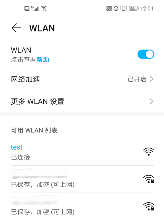
After successful connection, the development board will display that device HONOR_30 has joined wlan0 with IP
192.168.5.153.dnsmasq-dhcp: DHCPREQUEST(wlan0) 192.168.5.153 c2:31:4e:29:d5:6a dnsmasq-dhcp: DHCPACK(wlan0) 192.168.5.153 c2:31:4e:29:d5:6a HONOR_30-bffd2df053010722
Test Device Connectivity
Test network connectivity between the development board and the connected device:
```bash
# ping 192.168.5.153
PING 192.168.5.153 (192.168.5.153): 56 data bytes
64 bytes from 192.168.5.153: seq=0 ttl=64 time=8.818 ms
64 bytes from 192.168.5.153: seq=1 ttl=64 time=10.939 ms
64 bytes from 192.168.5.153: seq=2 ttl=64 time=15.955 ms
64 bytes from 192.168.5.153: seq=3 ttl=64 time=6.316 ms
```
4.3.21.5. Wi-Fi Performance Test
For Wi-Fi performance testing, please refer to Wi-Fi Performance Test.
4.3.21.6. Common Issues
Wi-Fi Interface Name Change
Phenomenon: The network interface name changes (e.g., from
wlan0to another name), causing the network interface defined in configuration files to become invalid, affecting network functionality.Analysis: The system enables udev rules that automatically assign names to network interfaces, potentially altering the default name
wlan0, especially triggered during driver or hardware initialization.Solution:
Use the
ethtool -i wlan0command to check the driver and firmware information of the network interfacewlan0:# ethtool -i wlan0 driver: rtl8852bs version: v1.19.7.1-91-gcb07686050.202404 firmware-version: N/A expansion-rom-version: bus-info: mmc2:0001:1 supports-statistics: yes supports-test: no supports-eeprom-access: no supports-register-dump: no supports-priv-flags: no
Delete the generated temporary rule file
/etc/udev/rules.d/70-persistent-net.rules.Add the following udev rule to restrict udev from renaming the wlan0 interface for the rtl8852bs driver:
echo 'SUBSYSTEM=="net", ACTION=="add", DRIVERS=="rtl8852bs", KERNEL=="wlan*", NAME="wlan0"'> /etc/udev/rules.d/99-disable-netname.rules
Restart the udev service or the system to apply the rule:
/etc/init.d/S10udev start
Communication Failure Error Codes
The following communication failure log appears:mmc2:0001:1: rtw_sdio_raw_read: sdio read failed (-110)
-110 Error Caused by CMD52
Phenomenon: CMD52 command timeout.
Analysis: CMD52 is a single-byte register operation command implemented purely in hardware.
Solution:
SDIO device is not powered properly; check power status.
Clock signal abnormality; ensure complete clock input.
-110 Error Caused by CMD53
Phenomenon: CMD53 command timeout.
Analysis: CMD53 is used for multi-block data read/write operations.
Solution:
Confirm that the driver and device tree configurations match the hardware, such as whether the correct SDIO controller is being used.
Poor data line signal quality; inspect DATA0~DATA3 connections, as flying wires may cause such issues.
Excessive clock frequency; try reducing the SDIO clock frequency (e.g., from 50 MHz to 25 MHz).
Modify the
bus-widthsetting in the SDIO node of the device tree to 1, using only the single data line DATA0 for communication.
SDIO Enumeration Failure
Phenomenon: No CMD signals observed on oscilloscope or no CMD logs in Dynamic Debug.
Analysis: Check whether the Card Detect pin exists on the module hardware and verify its configuration in the device tree.
Solution:
If the Wi-Fi module does not have a Card Detect pin, the “broken-cd” property must be added.
If power cycling of the Wi-Fi module is required, remove the “non-removable” field so that the host performs multiple detection attempts; otherwise, the Wi-Fi module will not be re-detected.