4.3.16. PMIC Driver Debugging Guide
4.3.16.1. PMIC Overview
PMIC (Power Management Integrated Circuit) is a highly integrated hardware module responsible for power distribution, voltage regulation, charge/discharge management, and system low-power control in electronic devices. In Linux systems, the PMIC interacts with the operating system through drivers and kernel frameworks, supporting dynamic power management, sleep/wakeup functionality, and more. The PMIC used on the X5 EVB is the HPU3501 chip.
4.3.16.2. PMIC Functional Description
Typical Applications of PMIC
Introduction to Typical PMIC Applications
Power Conversion and Distribution
DC-DC Converters: Efficiently convert input voltage into multiple different output voltages for use by the CPU, peripherals, etc.
LDO (Low Dropout Regulators): Suitable for low-power scenarios, providing stable voltage output (e.g., sensors, clock circuits).
System Power Control
Manages power-on/power-off sequences: responds to power button signals, controls CPU power-up timing and reset operations.
Dynamic Voltage and Frequency Scaling (DVFS): Dynamically adjusts core voltage based on CPU/GPU load to balance performance and power consumption.
Protection Mechanisms
Integrates overvoltage (OVP), undervoltage (UVP), overcurrent (OCP), and overtemperature (OTP) protection circuits to ensure safe system operation.
One typical application of a PMIC is thermal shutdown protection, implemented to prevent damage due to overheating and excessive power consumption. When thermal shutdown is triggered, the PMIC turns off all power rails until the junction temperature drops below a set threshold, after which the device resumes power-up. For more details, refer to the Thermal system debugging guide for driver platform section.
Introduction to HPU3501 Typical Applications
The PMIC currently used on the X5 EVB is the HPU3501, whose typical application is shown in the figure below:
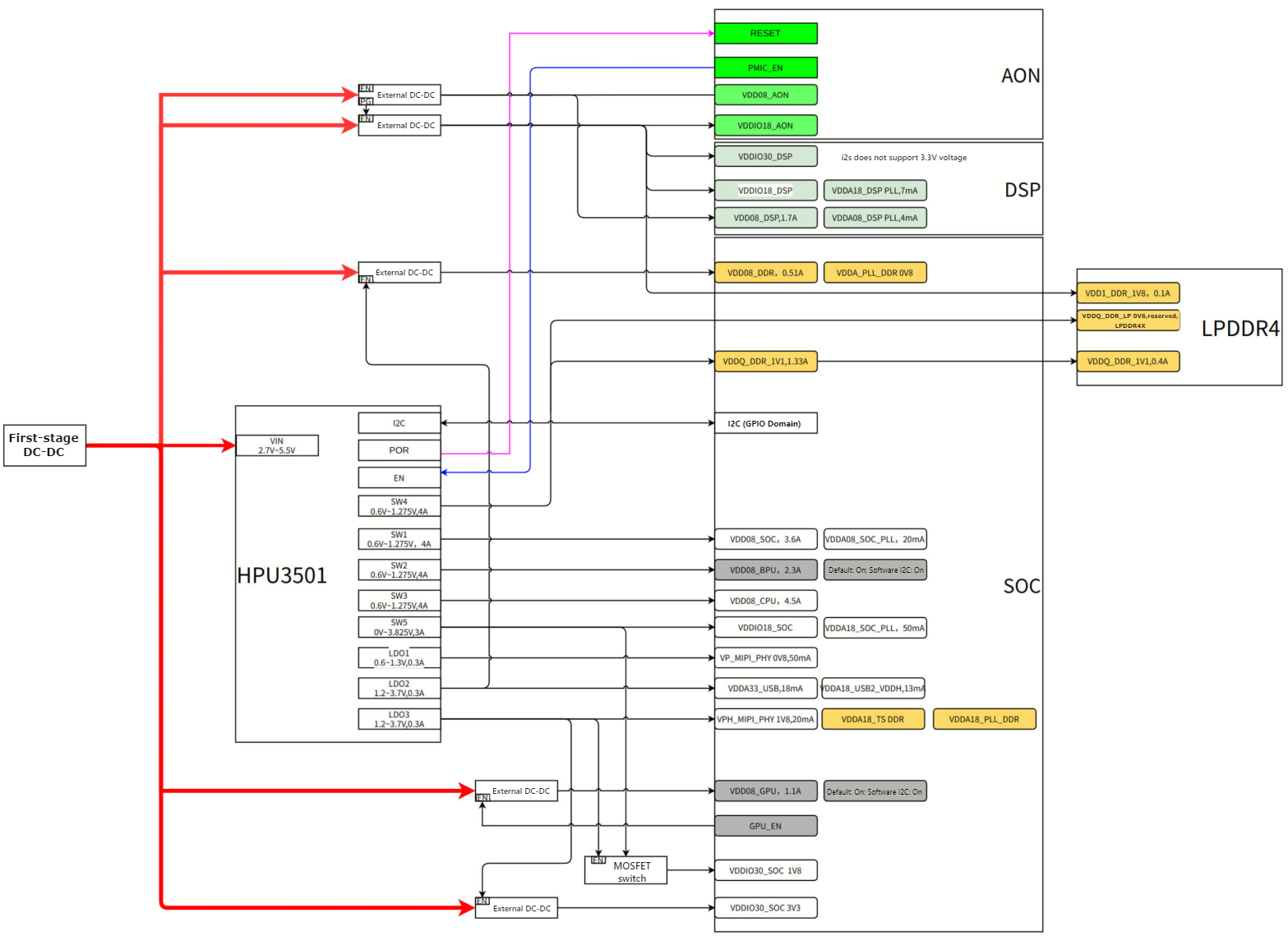
In the above diagram, HPU3501 acts as the core component, providing multiple voltage and current power rails to the X5 SoC via its internal switching regulators and low-dropout linear regulators, along with external DC/DC converters, while managing power through an I2C interface. Details are as follows:
Input Power:
5V IN: External power input, supplying power to the PMIC and other external DC/DC converters.
PMIC:
VIN (2.7V–5.5V): Main power input for the PMIC, accepting a voltage range of 2.7V to 5.5V.
I2C: I2C interface used to configure and monitor PMIC functions.
POR (Power-On Reset): Ensures the system starts in a known state upon power-up.
SWx (Switchers): Configurable switching regulators used to provide power rails with different voltages and currents. SW1 to SW5 are labeled in the diagram, each with different voltage and current specifications.
SW1: 0.6V–1.275V, max current 4A
SW2: 0.6V–1.275V, max current 4A
SW3: 0.6V–1.275V, max current 4A
SW4: 0.6V–1.275V, max current 4A
SW5: 0V–3.875V, max current 3A
LDOx (Low Dropout Regulators): Provide stable, low-noise power rails. LDO1 to LDO3 are labeled in the diagram, each with different voltage and current specifications.
LDO1: 0.6V–1.3V, max current 0.3A
LDO2: 1.2V–3.7V, max current 0.3A
LDO3: 1.2V–3.7V, max current 0.3A
X5 SoC Power Rails:
VDDx Series: These are power rails providing different voltages and currents to the X5 SoC, including:
VDD08_ANON, VDD08_DSP, VDD08_DSP_PLL, etc.: Power various modules of the SoC (e.g., analog, digital signal processing, PLLs).
VDD08_DDR, VDDQ_DDR_IV1, VDDA_PLL_DDR 0V8: Supply power to DDR memory.
VDD08_SOC, VDD08_BPU, VDD08_CPU: Power core components of the SoC (e.g., CPU, BPU).
VDD08_SOC_PLL, VDDAIR_SOC_PLL: Supply power to SoC PLLs.
VP_MIPI_PHY 0V8: Supply power to the MIPI interface.
VDDAIR1_USB, VDDAIR1_USER2_VOOH: Supply power to USB and user interfaces.
VDDAIR8_PHY 1V8, VDDAIR8_PLL_DDR: Supply power to PHY and PLL.
VDD08_GPU: Supply power to the GPU.
VDD08_SOC_1V8: Provide 1.8V power to other parts of the SoC.
VDD08_SOC_5V3: Provide 5.3V power to the SoC.
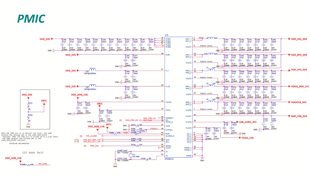
The schematic of the PMIC module circuit on the X5 EVB is as follows:
PMIC Functional Principles
The core working principle of a PMIC is to ensure stable and efficient system operation by integrating various power management functions. It provides voltage regulation, power distribution, current protection, and other functions to maintain system stability and energy efficiency under varying workloads, while also implementing power control and protective measures when necessary.
Below are explanations of some core functional principles of the PMIC:
Voltage Regulation
Voltage Conversion: The PMIC contains multiple voltage regulators internally that can convert the input supply voltage into different stable output voltages, powering various modules within the system (such as CPU, GPU, memory, peripherals, etc.).
Voltage Adjustment: By adjusting the output voltage, the PMIC can modify power delivery based on system demand—reducing power consumption or increasing voltage to meet load requirements. This is typically associated with Dynamic Voltage and Frequency Scaling (DVFS), optimizing power consumption under varying loads.
Power Distribution
The PMIC manages power rails (power channels) for various components in the system, ensuring each module receives appropriate power. It allocates power to the CPU, GPU, memory, peripherals, and dynamically adjusts voltage and current according to system load to optimize energy efficiency.
Current and Power Protection
Overcurrent Protection: The PMIC includes overcurrent protection to prevent current from exceeding preset safety thresholds, thus avoiding damage to the device.
Overtemperature Protection: The PMIC monitors temperature; if the CPU or other monitored components overheat, it takes measures to reduce power or disable certain functions to prevent thermal damage.
4.3.16.3. PMIC Driver Code
PMIC Driver Framework
In the Linux kernel, the PMIC driver is responsible for initializing and managing the hardware functions of the Power Management Integrated Circuit (PMIC). It leverages the MFD (Multi-Function Device) framework to handle multiple functional units (called Cells), creating a Platform device for each Cell. The MFD framework handles device registration and deregistration, as well as managing Cell operations. The Regulator framework defines and manages the behavior of voltage regulators, including voltage and current regulation. Regmap is an interface that provides a generic method for communicating with PMIC registers, typically used for I2C or SPI communication. The following sections will introduce these driver frameworks individually and explain their interrelationships within the PMIC driver.
Introduction to the MFD Framework
The PMIC driver is a typical example of the MFD framework. MFD is a software framework in Linux used to manage and control multi-function devices. It provides a unified interface allowing multiple devices to be managed and controlled through a single driver.
In the MFD framework, each independent functional unit is referred to as a “cell.” The MFD subsystem in the Linux kernel creates corresponding platform devices for these cells, enabling independent management.
The MFD subsystem consists of three main components:
MFD Core:
Provides device registration and deregistration functionality. When an MFD device is recognized by the system, the MFD Core adds it to the system; when the device is no longer used or needs to be removed, the MFD Core deregisters it.
Manages operations on Cells. A Cell is a functional unit within an MFD device, such as a voltage regulator. The MFD Core allows identification and configuration of these Cells.
MFD Device Driver:
This is the software component that interacts with the MFD device. It uses interfaces provided by the MFD Core to register the device, create Cells, and manage their behavior. The driver implements the specific details of hardware interaction, such as reading from and writing to registers.
MFD Cell Descriptor:
A descriptor is a data structure used to describe each Cell within an MFD device. It contains characteristics and configuration information about the Cell, such as its name, function, register mapping, etc.
The MFD creates a Platform device for each Cell. This means each Cell can be treated as an independent device, accessible and controllable via standard Platform device interfaces.
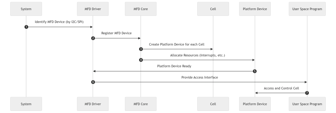
MFD Workflow:
When an MFD device is recognized by the system (e.g., via I2C or SPI bus), the MFD device driver uses the MFD Core interface to register the device.
The MFD Core creates a Platform device for each Cell in the device and allocates resources such as interrupts to these Platform devices.
Drivers and user-space programs can access and control each Cell via the Platform device interface, thereby achieving management and control of the MFD device.
This process is illustrated in the figure below:
Introduction to the Regulator Framework
Each voltage regulator in the PMIC (such as DC-DC converters or LDOs) is managed through the Regulator framework.
The Regulator framework is a subsystem in the Linux kernel used to manage power regulators. It provides a standardized way to manage power switching, voltage and current settings, and dynamic output adjustment.
In the Linux voltage and current regulator framework documentation, a series of terms related to power regulators are defined. These terms describe various components and their functions within the power management framework. Below is a brief introduction to these terms:
1. Regulator:
Definition: An electronic device that supplies power to other devices.
Function: Most regulators can enable or disable their output; some can also control output voltage and/or current.
Example:
Input Voltage -> Regulator -> Output Voltage
2. PMIC (Power Management Integrated Circuit):
Definition: An integrated circuit containing multiple regulators, often including other subsystems.
Function: Used to manage system power distribution and power management functions.
3. Consumer:
Definition: An electronic device powered by a regulator.
Classification:
Static Consumer: Does not require changes to its supply voltage or current limits, only needs power to be enabled or disabled. Its supply voltage is set by hardware, bootloader, firmware, or kernel board initialization code.
Dynamic Consumer: Requires changes to its supply voltage or current limits based on operational needs.
4. Power Domain:
Definition: Electronic circuits powered by a regulator, switch, or output of another power domain.
-
Regulator -+-> Switch-1 -+-> Switch-2 --> [Consumer A]
           |             |
           |             +-> [Consumer B], [Consumer C]
           |
           +-> [Consumer D], [Consumer E]
This illustrates one regulator and three power domains:
Power Domain 1: Switch-1, consumers D and E.
Power Domain 2: Switch-2, consumers B and C.
Power Domain 3: Consumer A. There are supply relationships among these domains:
Domain-1 --> Domain-2 --> Domain-3
5. Constraints:
Definition: Power levels defined for performance and hardware protection.
Classification:
Regulator Level: Defined by the operational parameters of the regulator hardware, typically specified in the regulator’s datasheet. For example:
Output voltage range: 800mV to 3500mV.
Current output limit: 20mA at 5V, 10mA at 10V.
Power Domain Level: Defined in software by kernel-level board initialization code to limit the power range of the domain. For example, in the Power Domain structure above:
Domain 1 voltage: 3300mV.
Domain 2 voltage range: 1400mV to 1600mV.
Domain 3 current limit: 0mA to 20mA.
Consumer Level: Voltage or current limits dynamically set by the consumer driver. For example:
A backlight driver requests increasing current from 5mA to 10mA to enhance LCD illumination.
In the Linux kernel, the Regulator framework controls voltage output through a series of software interfaces and hardware abstraction layers. The Regulator framework primarily consists of the following components:
Machine Interface:
This layer typically refers to platform-specific configuration information defined through the Device Tree. The Device Tree describes all hardware components in the system, including regulator attributes such as supported voltage ranges, maximum current, default settings, etc.
In the Regulator framework, machine-level information is used to initialize the regulator driver, ensuring the regulator is configured according to hardware design requirements.
Regulator Driver Interface:
The regulator driver is part of the kernel responsible for direct hardware interaction and control of the regulator. This includes enabling/disabling the regulator, setting voltage and current, etc.
Regulator drivers are typically registered into the kernel via the Platform Driver model and can be hardware-specific or generic.
Consumer:
Consumers are devices or modules in the system that rely on regulator-supplied power. These devices request power through the Regulator framework and release it when no longer needed.
Consumers interact with the regulator driver via kernel APIs such as
regulator_get()andregulator_put()to acquire and release regulators, andregulator_enable()andregulator_disable()to control power.
Sys-Class-Regulator (User-Space Interface):
This component provides an interface for user-space programs to interact with the kernel regulator framework. Through the sysfs file system, user-space programs can query regulator status (e.g., current voltage and current) or change regulator settings.
This interface enables user-space programs to dynamically manage system power, such as adjusting voltage to optimize performance or save energy.
See kernel documentation:
kernel/Documentation/ABI/testing/sysfs-class-regulator.
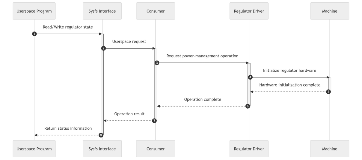
The Linux Regulator Framework in actual drivers is shown in the figure below:
Explanation:
User Space Program (User_Space): Initiates read or write requests for regulator status.
Sysfs Interface (Sysfs_Interface): Acts as the interface between user space and kernel space, receiving user requests and forwarding them to the appropriate Consumer.
Consumer: Represents devices or modules in the system using regulator power; they request power management operations via the Sysfs interface.
Regulator Driver (Regulator_Driver): Kernel regulator driver responsible for handling Consumer requests and interacting with hardware to perform power management operations.
Machine: Represents platform-specific configuration information used to initialize regulator hardware.
Introduction to the Regmap Framework
Regmap (Register Map) is a framework in the Linux kernel designed to simplify access to hardware registers. It provides a unified set of APIs for reading and writing hardware registers, and supports caching mechanisms to improve efficiency.
Based on code reuse principles, the Linux kernel introduced the regmap model, which abstracts common logic for register access. Driver developers no longer need to concern themselves with SPI or I2C interface API functions but instead uniformly use regmap API functions. This approach reduces code redundancy and improves driver portability. Key features of the regmap model include:
It provides a unified set of interface functions (e.g.,
regmap_readandregmap_write) for accessing device registers, including those inside SoCs.Regmap was designed in the Linux kernel to reduce redundant overhead from slow I/O operations in driver development, offering a generic interface for hardware register operations.
Regmap introduces a caching mechanism between the driver and hardware, reducing the number of slow I/O operations and improving access efficiency, though potentially at the cost of real-time performance.
The entire Regmap is divided into three layers, with the following topology:
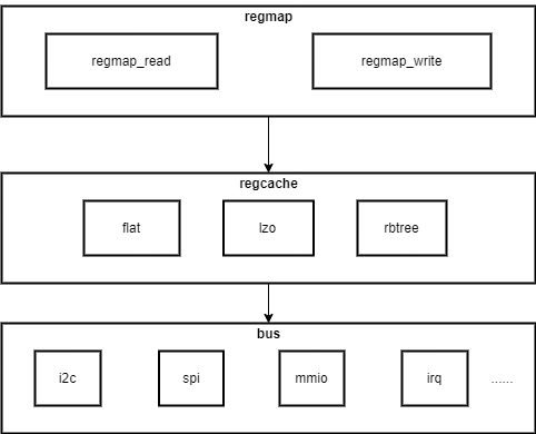
This diagram shows a simplified topology of the regmap subsystem in the Linux kernel. The regmap subsystem simplifies hardware register access through a unified interface and supports various bus types. Below is an analysis of each layer:
The regmap layer provides generic read/write interfaces:
regmap_read and regmap_write: The two main interfaces provided by the regmap subsystem for reading from and writing to hardware registers. These interfaces hide the specific bus operation details from upper-layer drivers.
The regcache layer manages caching to improve efficiency:
regcache: This layer manages register caching. Regmap can use caching to reduce hardware access frequency, improving performance. The diagram lists several different cache implementations:
flat: Array-based, simple flat cache without complex data structures. Suitable when the device has few registers.
lzo: Cache using the LZO (Lempel–Ziv–Oberhumer) compression algorithm, suitable for scenarios requiring compression of large amounts of register data. This algorithm has three characteristics:
Fast compression
Decompression requires no extra memory
Compression ratio is adjustable
Can be viewed as an array cache with an added compression layer to save memory. Consider this type when the number of device registers is moderate.
rbtree: Cache implemented using a red-black tree (a self-balancing binary search tree), characterized by fast indexing. Use this type when the number of device registers is large or when low register operation latency is required.
The bus layer handles interaction with specific hardware buses:
bus: This layer defines specific methods for interacting with different bus types. Each bus type has its own implementation to support the regmap interface. The diagram lists several common bus types:
i2c: Implementation for I2C bus.
spi: Implementation for SPI bus.
mmio: Implementation for Memory-Mapped I/O.
irq: Implementation for interrupts.
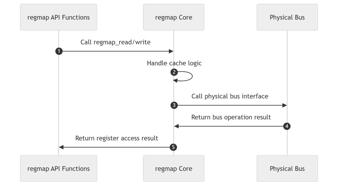
The corresponding regmap driver framework has three main components: regmap API functions, regmap core, and the physical bus layer:
regmap API Functions
This layer provides a set of API functions to simplify register read/write operations. These are the external interfaces of the regmap framework, allowing drivers to access hardware registers uniformly without worrying about underlying bus types or register access details.regmap Core
This is the core of the regmap framework, responsible for managing register caching and supporting different caching strategies. The choice of caching strategy can affect performance and resource usage.Physical Bus Layer
This layer defines specific methods for interacting with different physical buses. Each bus type has its own implementation to support regmap API functions. These buses include:
The interaction process between layers of the regmap driver framework is shown in the figure below:
Explanation of the PMIC Driver Framework
First, clarify the relationships among PMIC, MFD, Regulator, and Regmap:
PMIC and MFD:
The PMIC hardware is registered into the kernel via the MFD framework. The MFD framework abstracts each function of the PMIC into a Cell and creates a Platform device for each Cell.
For example, the hpu3501 PMIC chip is registered via the MFD framework, with each function (e.g., LDO or DC-DC converter) abstracted as a Cell.
MFD and Regulator:
The MFD framework acts as an intermediary layer, abstracting each functional module of the PMIC into independent devices. The Platform devices created by the MFD framework for each Cell can be used by the Regulator framework. The Regulator framework communicates with the PMIC hardware through these Platform devices.
For example, the MFD framework creates a Platform device for each LDO in hpu3501, and the Regulator framework controls voltage and current through these devices.
Regulator and Regmap:
The Regulator framework communicates with the PMIC hardware through the Regmap framework. Regmap provides register access APIs, and the Regulator framework uses these APIs to read from and write to PMIC registers.
For example, the Regulator framework uses the
regmap_writefunction to set the PMIC’s voltage control register.
In short, the MFD framework manages the multi-functional units of the PMIC, the Regulator framework controls the voltage regulators, and Regmap handles communication with the PMIC’s registers.
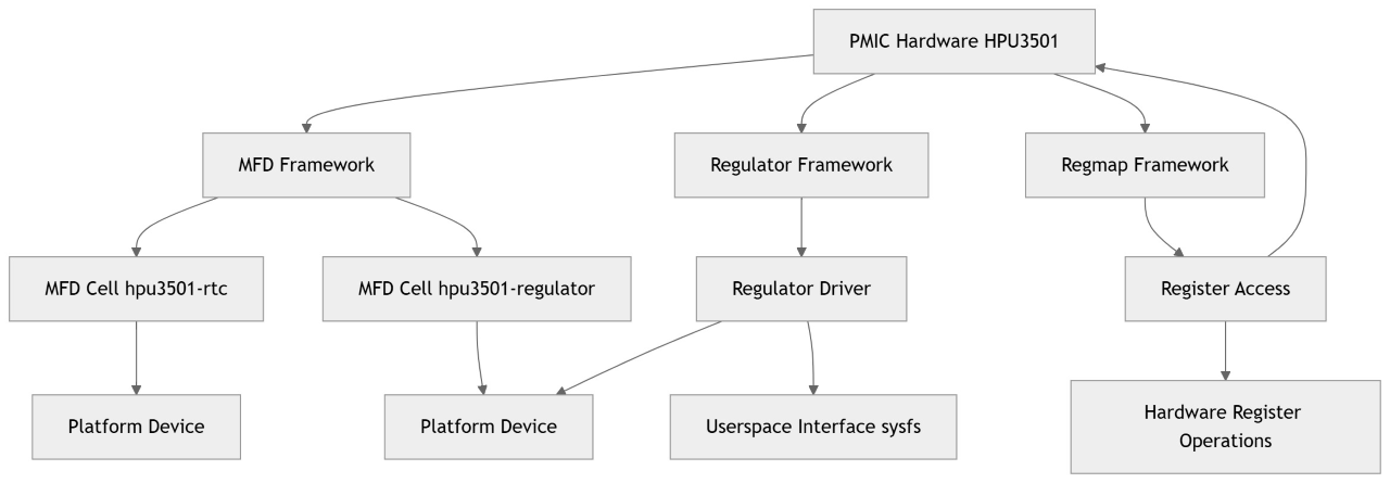
Taking hpu3501 on the X5 EVB as an example, the above relationships can be illustrated as follows:
The PMIC driver framework can be described as follows:
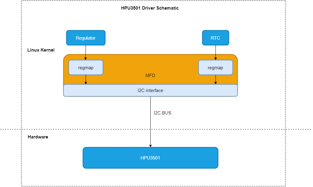
The hpu3501 hardware supports multiple functions, such as RTC and Regulator, so the Linux MFD architecture is adopted as the overall architecture for both Regulator and RTC.
As shown in the figure, the main role of the MFD layer is to register the I2C device, communicate with the hardware HPU3501 via the I2C bus, and provide a unified register read/write interface to the Regulator and RTC via the regmap method.
RTC mainly handles time and alarm settings and read/write operations.
The Regulator mainly controls various power rails.
Introduction to MFD Driver Code
MFD Config Switch
CONFIG_MFD_CORE=y
The CONFIG_MFD_CORE configuration option enables the MFD (Multi-Function Device) core framework.
MFD Code Path
kernel/drivers/mfd/mfd-core.c
kernel/include/linux/mfd/core.h
Key MFD Code Introduction
Key data structures in the MFD driver code are as follows:
// kernel/include/linux/mfd/core.h
/*
 * This struct describes the MFD part ("cell").
 * After registration the copy of this structure will become the platform data
 * of the resulting platform_device
 */
struct mfd_cell {
	const char		*name;
	int			id;
	int			level;

	int			(*enable)(struct platform_device *dev);
	int			(*disable)(struct platform_device *dev);

	int			(*suspend)(struct platform_device *dev);
	int			(*resume)(struct platform_device *dev);

	/* platform data passed to the sub devices drivers */
	void			*platform_data;
	size_t			pdata_size;

	/* Software node for the device. */
	const struct software_node *swnode;

	/*
	 * Device Tree compatible string
	 * See: Documentation/devicetree/usage-model.rst Chapter 2.2 for details
	 */
	const char		*of_compatible;

	/*
	 * Address as defined in Device Tree.  Used to complement 'of_compatible'
	 * (above) when matching OF nodes with devices that have identical
	 * compatible strings
	 */
	u64 of_reg;

	/* Set to 'true' to use 'of_reg' (above) - allows for of_reg=0 */
	bool			use_of_reg;

	/* Matches ACPI */
	const struct mfd_cell_acpi_match	*acpi_match;

	/*
	 * These resources can be specified relative to the parent device.
	 * For accessing hardware you should use resources from the platform dev
	 */
	int			num_resources;
	const struct resource	*resources;

	/* don't check for resource conflicts */
	bool			ignore_resource_conflicts;

	/*
	 * Disable runtime PM callbacks for this subdevice - see
	 * pm_runtime_no_callbacks().
	 */
	bool			pm_runtime_no_callbacks;

	/* A list of regulator supplies that should be mapped to the MFD
	 * device rather than the child device when requested
	 */
	const char * const	*parent_supplies;
	int			num_parent_supplies;
};
The struct mfd_cell structure in the MFD subsystem describes a functional unit (called a “cell”) of an MFD device. This structure contains various information needed to create a platform device, and after the MFD device is registered, a copy of this structure becomes the platform data of the resulting platform_device.
In the Linux kernel, a set of function interfaces is provided to enable and disable units (cells) in MFD devices, add and remove MFD devices, and retrieve MFD cells associated with platform devices. Below is an introduction to these function interfaces:
mfd_cell_enableandmfd_cell_disableThese two functions are used to enable and disable units in an MFD device. They automatically handle reference counting, ensuring that the unit’s enable or disable callback is only invoked when the device is first enabled or when no other client is using it.
extern int mfd_cell_enable(struct platform_device *pdev);
extern int mfd_cell_disable(struct platform_device *pdev);
mfd_cell_enable(pdev): Enables the MFD cell corresponding to the specified platform device (pdev).mfd_cell_disable(pdev): Disables the MFD cell corresponding to the specified platform device (pdev).
mfd_get_cellThis inline function retrieves the MFD cell that created a specific platform device.
static inline const struct mfd_cell *mfd_get_cell(struct platform_device *pdev)
{
	return pdev->mfd_cell;
}
mfd_get_cell(pdev): Returns a pointer to the MFD cell associated with the given platform device (pdev).
mfd_add_devicesThis function adds a group of MFD devices. It accepts parameters such as the parent device, device ID, array of MFD cells, number of devices, memory resource base address, interrupt base address, and interrupt domain.
extern int mfd_add_devices(struct device *parent, int id,
			   const struct mfd_cell *cells, int n_devs,
			   struct resource *mem_base,
			   int irq_base, struct irq_domain *irq_domain);
mfd_add_devices(parent, id, cells, n_devs, mem_base, irq_base, irq_domain): Adds multiple MFD devices under the specified parent device.
mfd_add_hotplug_devicesThis inline function is a special case of
mfd_add_devices, used to add hot-pluggable MFD devices. It automatically sets the device ID to auto-allocate (PLATFORM_DEVID_AUTO) and ignores memory base, interrupt base, and interrupt domain.static inline int mfd_add_hotplug_devices(struct device *parent, const struct mfd_cell *cells, int n_devs) { return mfd_add_devices(parent, PLATFORM_DEVID_AUTO, cells, n_devs, NULL, 0, NULL); }
mfd_add_hotplug_devices(parent, cells, n_devs): Adds multiple hot-pluggable MFD devices under the specified parent device.
mfd_remove_devicesandmfd_remove_devices_lateThese two functions remove previously added MFD devices.
extern void mfd_remove_devices(struct device *parent);
extern void mfd_remove_devices_late(struct device *parent);
mfd_remove_devices(parent): Removes all MFD devices under the specified parent device.mfd_remove_devices_late(parent): Removes all MFD devices under the specified parent device during system shutdown.
devm_mfd_add_devicesThis function adds a group of MFD devices and automatically removes them when the device is released. It is similar to
mfd_add_devicesbut provides device model (devm) support for automatic resource management.extern int devm_mfd_add_devices(struct device *dev, int id, const struct mfd_cell *cells, int n_devs, struct resource *mem_base, int irq_base, struct irq_domain *irq_domain);
devm_mfd_add_devices(dev, id, cells, n_devs, mem_base, irq_base, irq_domain): Adds multiple MFD devices under the specified device and automatically removes them when the device is released.
Introduction to Regulator Driver Code
Regulator Config Switch
CONFIG_REGULATOR=y
CONFIG_REGULATOR_DEBUG=y
CONFIG_REGULATOR_FIXED_VOLTAGE=y
CONFIG_REGULATOR_GPIO=y
CONFIG_REGULATORenables the regulator framework. This framework manages voltage and current regulators that provide stable power to different components in the system.CONFIG_REGULATOR_DEBUGenables debugging features in the regulator framework.CONFIG_REGULATOR_FIXED_VOLTAGEenables support for fixed-voltage regulators—simple regulators that provide a constant output voltage.CONFIG_REGULATOR_GPIOenables support for regulators controlled via GPIO (General Purpose Input/Output).
Regulator Code Path
kernel/include/linux/regulator/driver.h
kernel/drivers/regulator/core.c
kernel/drivers/regulator/devres.c
kernel/drivers/regulator/irq_helpers.c
Introduction to Key Regulator Code
The key data structures in the Regulator driver code are as follows:
// kernel/include/linux/regulator/driver.h
struct regulator_desc {
	const char *name;
	const char *supply_name;
	const char *of_match;
	bool of_match_full_name;
	const char *regulators_node;
	int (*of_parse_cb)(struct device_node *,
			    const struct regulator_desc *,
			    struct regulator_config *);
	int id;
	unsigned int continuous_voltage_range:1;
	unsigned n_voltages;
	unsigned int n_current_limits;
	const struct regulator_ops *ops;
	int irq;
	enum regulator_type type;
	struct module *owner;

	unsigned int min_uV;
	unsigned int uV_step;
	unsigned int linear_min_sel;
	int fixed_uV;
	unsigned int ramp_delay;
	int min_dropout_uV;

	const struct linear_range *linear_ranges;
	const unsigned int *linear_range_selectors;

	int n_linear_ranges;

	const unsigned int *volt_table;
	const unsigned int *curr_table;

	......

	unsigned int n_ramp_values;

	unsigned int enable_time;

	unsigned int off_on_delay;

	unsigned int poll_enabled_time;

	unsigned int (*of_map_mode)(unsigned int mode);
};
The struct regulator_desc is a data structure in the Linux kernel used to describe static information of a voltage or current regulator. It contains core attributes and operation interfaces of the regulator, which are provided to the regulator framework when the regulator driver is registered.
// kernel/include/linux/regulator/driver.h
struct regulator_dev {
	const struct regulator_desc *desc;
	int exclusive;
	u32 use_count;
	u32 open_count;
	u32 bypass_count;

	/* lists we belong to */
	struct list_head list; /* list of all regulators */

	/* lists we own */
	struct list_head consumer_list; /* consumers we supply */

	struct coupling_desc coupling_desc;

	struct blocking_notifier_head notifier;
	struct ww_mutex mutex; /* consumer lock */
	struct task_struct *mutex_owner;
	int ref_cnt;
	struct module *owner;
	struct device dev;
	struct regulation_constraints *constraints;
	struct regulator *supply;	/* for tree */
	const char *supply_name;
	struct regmap *regmap;

	struct delayed_work disable_work;

	void *reg_data;		/* regulator_dev data */

	struct dentry *debugfs;

	struct regulator_enable_gpio *ena_pin;
	unsigned int ena_gpio_state:1;

	unsigned int is_switch:1;

	/* time when this regulator was disabled last time */
	ktime_t last_off;
	int cached_err;
	bool use_cached_err;
	spinlock_t err_lock;
};
The struct regulator_dev defines the core data structure for voltage/current regulator devices in the Linux kernel. It includes state information, operation interfaces, consumer lists, etc. Through this structure, the regulator framework can manage and control regulator behavior, while providing a unified interface to other kernel subsystems or user-space programs. Each regulator instance has such a structure.
// kernel/include/linux/regulator/driver.h
struct regulator_ops {

	/* enumerate supported voltages */
	int (*list_voltage) (struct regulator_dev *, unsigned selector);

	/* get/set regulator voltage */
	int (*set_voltage) (struct regulator_dev *, int min_uV, int max_uV,
			    unsigned *selector);
        ......

	/* get/set regulator current  */
	int (*set_current_limit) (struct regulator_dev *,
				 int min_uA, int max_uA);
	int (*get_current_limit) (struct regulator_dev *);

	......

	/* enable/disable regulator */
	int (*enable) (struct regulator_dev *);
	int (*disable) (struct regulator_dev *);

        ......

	/* report regulator status ... most other accessors report
	 * control inputs, this reports results of combining inputs
	 * from Linux (and other sources) with the actual load.
	 * returns REGULATOR_STATUS_* or negative errno.
	 */
	int (*get_status)(struct regulator_dev *);

	/* get most efficient regulator operating mode for load */
	unsigned int (*get_optimum_mode) (struct regulator_dev *, int input_uV,
					  int output_uV, int load_uA);
	/* set the load on the regulator */
	int (*set_load)(struct regulator_dev *, int load_uA);

	/* control and report on bypass mode */
	int (*set_bypass)(struct regulator_dev *dev, bool enable);
	int (*get_bypass)(struct regulator_dev *dev, bool *enable);

	/* the operations below are for configuration of regulator state when
	 * its parent PMIC enters a global STANDBY/HIBERNATE state */

	/* set regulator suspend voltage */
	int (*set_suspend_voltage) (struct regulator_dev *, int uV);

	/* enable/disable regulator in suspend state */
	int (*set_suspend_enable) (struct regulator_dev *);
	int (*set_suspend_disable) (struct regulator_dev *);

	/* set regulator suspend operating mode (defined in consumer.h) */
	int (*set_suspend_mode) (struct regulator_dev *, unsigned int mode);

	int (*resume)(struct regulator_dev *rdev);

	int (*set_pull_down) (struct regulator_dev *);
};
The struct regulator_ops defines a set of operation interfaces for voltage/current regulators in the Linux kernel. These operations are implemented by the regulator chip driver to control the regulator’s behavior.
The Linux kernel Regulator subsystem provides a series of function interfaces for operations such as registration, deregistration, event notification, interrupt handling, and voltage mapping. Below is a brief description of these function interfaces:
Regulator Registration and Deregistration
The following functions are used to register and deregister regulator devices in the kernel:
// kernel/drivers/regulator/core.c
struct regulator_dev *regulator_register(struct device *dev,
                                     const struct regulator_desc *regulator_desc,
                                     const struct regulator_config *config);
// kernel/drivers/regulator/devres.c
struct regulator_dev *devm_regulator_register(struct device *dev,
                                             const struct regulator_desc *regulator_desc,
                                             const struct regulator_config *config);
// kernel/drivers/regulator/devres.c
void regulator_unregister(struct regulator_dev *rdev);
regulator_register: Registers a single regulator device.devm_regulator_register: Registers a regulator device and automatically deregisters it when the device is destroyed.regulator_unregister: Deregisters a previously registered regulator device.
Event Notification
Functions used to handle regulator events:
// kernel/drivers/regulator/core.c
int regulator_notifier_call_chain(struct regulator_dev *rdev,
                                 unsigned long event, void *data);
regulator_notifier_call_chain: Triggers a regulator event and notifies all registered listeners.
Interrupt Handling
The following functions are used to handle interrupts related to regulators:
// kernel/drivers/regulator/devres.c
void *devm_regulator_irq_helper(struct device *dev,
                                 const struct regulator_irq_desc *d, int irq,
                                 int irq_flags, int common_errs,
                                 int *per_rdev_errs, struct regulator_dev **rdev,
                                 int rdev_amount);
// kernel/drivers/regulator/irq_helpers.c
void *regulator_irq_helper(struct device *dev,
                         const struct regulator_irq_desc *d, int irq,
                         int irq_flags, int common_errs, int *per_rdev_errs,
                         struct regulator_dev **rdev, int rdev_amount);
// kernel/drivers/regulator/irq_helpers.c
void regulator_irq_helper_cancel(void **handle);
devm_regulator_irq_helper: Uses device manager to assist in handling regulator interrupts.regulator_irq_helper: Helps handle regulator interrupts.regulator_irq_helper_cancel: Cancels a previously registered interrupt handler.
Regulator Operations
The following functions are used to retrieve information and status of regulator devices:
// kernel/drivers/regulator/core.c
void *rdev_get_drvdata(struct regulator_dev *rdev);
// kernel/drivers/regulator/core.c
struct device *rdev_get_dev(struct regulator_dev *rdev);
// kernel/drivers/regulator/core.c
struct regmap *rdev_get_regmap(struct regulator_dev *rdev);
// kernel/drivers/regulator/core.c
int rdev_get_id(struct regulator_dev *rdev);
rdev_get_drvdata: Retrieves private data of the regulator.rdev_get_dev: Retrieves the device structure of the regulator.rdev_get_regmap: Retrieves the register map of the regulator.rdev_get_id: Retrieves the ID of the regulator.
Voltage Mapping and Control
The following functions are used to handle voltage mapping and regulator control operations:
// kernel/drivers/regulator/irq_helpers.c
int regulator_list_voltage_linear(struct regulator_dev *rdev,
                                 unsigned int selector);
// kernel/drivers/regulator/irq_helpers.c
int regulator_map_voltage_linear(struct regulator_dev *rdev,
                                 int min_uV, int max_uV);
// kernel/drivers/regulator/irq_helpers.c
int regulator_set_voltage_sel_regmap(struct regulator_dev *rdev, unsigned sel);
// kernel/drivers/regulator/irq_helpers.c
int regulator_enable_regmap(struct regulator_dev *rdev);
// kernel/drivers/regulator/irq_helpers.c
int regulator_disable_regmap(struct regulator_dev *rdev);
regulator_list_voltage_linear: Lists supported voltage values of the regulator (linear mapping).regulator_map_voltage_linear: Maps a voltage value to a regulator selector value (linear mapping).regulator_set_voltage_sel_regmap: Sets the regulator’s voltage selector value via the regmap interface.regulator_enable_regmap: Enables the regulator via the regmap interface.regulator_disable_regmap: Disables the regulator via the regmap interface.
Helper Functions
The following functions are used for auxiliary operations before registering a regulator:
// kernel/drivers/regulator/irq_helpers.c
int regulator_desc_list_voltage_linear_range(const struct regulator_desc *desc,
                                             unsigned int selector);
regulator_desc_list_voltage_linear_range: Lists supported voltage values based on the regulator descriptor (linear range).
These categories cover the main operations and functionalities in the regulator subsystem, enabling kernel developers to conveniently manage and operate voltage/current regulators.
Introduction to Regmap Driver Code
Regmap Config Options
CONFIG_REGMAP=y
CONFIG_REGMAP_I2C=y
CONFIG_REGMAP_SPI=y
CONFIG_REGMAP_MMIO=y
CONFIG_REGMAP_TEE=y
CONFIG_REGMAP=yThis option enables the regmap subsystem.
ymeans the option is compiled into the kernel. Regmap is a generic register mapping and access framework that provides a unified register access interface for different buses (e.g., I2C, SPI).
CONFIG_REGMAP_I2C=yThis option enables support for the I2C bus. When enabled, the regmap subsystem can communicate with devices over the I2C bus.
CONFIG_REGMAP_SPI=yThis option enables support for the SPI bus. Once enabled, the regmap subsystem can access device registers via the SPI bus.
CONFIG_REGMAP_MMIO=yThis option enables support for memory-mapped I/O (MMIO). It allows the regmap subsystem to directly access hardware registers through memory addresses.
CONFIG_REGMAP_TEE=yThis option enables support for Trusted Execution Environment (TEE). TEE is a security mechanism used to protect sensitive operations from malicious software. When enabled, the regmap subsystem can interact with TEE, typically used for secure register access.
Regmap Code Paths
kernel/include/linux/regmap.h
kernel/drivers/base/regmap/internal.h
Introduction to Key Regmap Code
The key data structures in the Regmap driver are as follows:
// kernel/include/linux/regmap.h
struct regmap_config {
	const char *name;

	int reg_bits;
	int reg_stride;
	int reg_downshift;
	unsigned int reg_base;
	int pad_bits;
	int val_bits;

	bool (*writeable_reg)(struct device *dev, unsigned int reg);
	bool (*readable_reg)(struct device *dev, unsigned int reg);
	bool (*volatile_reg)(struct device *dev, unsigned int reg);
	bool (*precious_reg)(struct device *dev, unsigned int reg);
	bool (*writeable_noinc_reg)(struct device *dev, unsigned int reg);
	bool (*readable_noinc_reg)(struct device *dev, unsigned int reg);

        ......

	unsigned int num_ranges;

	bool use_hwlock;
	bool use_raw_spinlock;
	unsigned int hwlock_id;
	unsigned int hwlock_mode;

	bool can_sleep;
};
The struct regmap_config is used to configure the regmap subsystem in the Linux kernel.
// kernel/drivers/base/regmap/internal.h
struct regcache_ops {
	const char *name;
	enum regcache_type type;
	int (*init)(struct regmap *map);
	int (*exit)(struct regmap *map);
#ifdef CONFIG_DEBUG_FS
	void (*debugfs_init)(struct regmap *map);
#endif
	int (*read)(struct regmap *map, unsigned int reg, unsigned int *value);
	int (*write)(struct regmap *map, unsigned int reg, unsigned int value);
	int (*sync)(struct regmap *map, unsigned int min, unsigned int max);
	int (*drop)(struct regmap *map, unsigned int min, unsigned int max);
};
The struct regcache_ops defines a set of operations for the register cache (regcache). In the regmap framework, the register cache is an optional mechanism used to store device register values to reduce hardware access and improve performance.
// kernel/include/linux/regmap.h
struct regmap_bus {
	bool fast_io;
	regmap_hw_write write;
	regmap_hw_gather_write gather_write;
	regmap_hw_async_write async_write;
	regmap_hw_reg_write reg_write;
	regmap_hw_reg_noinc_write reg_noinc_write;
	regmap_hw_reg_update_bits reg_update_bits;
	regmap_hw_read read;
	regmap_hw_reg_read reg_read;
	regmap_hw_reg_noinc_read reg_noinc_read;
	regmap_hw_free_context free_context;
	regmap_hw_async_alloc async_alloc;
	u8 read_flag_mask;
	enum regmap_endian reg_format_endian_default;
	enum regmap_endian val_format_endian_default;
	size_t max_raw_read;
	size_t max_raw_write;
	bool free_on_exit;
};
The regmap_bus structure defines a set of function pointers and attributes used to perform various register access operations such as read/write, bulk write, asynchronous write, etc. These operations are typically implemented by specific bus drivers, such as I2C or SPI drivers.
Commonly used function interfaces in Regmap are as follows:
regmap_read
Function: Attempts to read data from a specified register address.
Function prototype:
static inline int regmap_read(struct regmap *map, unsigned int reg, unsigned int *val);
Parameters:
struct regmap *map: Pointer to the regmap structure describing the register mapping.unsigned int reg: Register address to read.unsigned int *val: Pointer to a buffer where the read value will be stored.
Return value: Returns
-EINVALand issues a warning if the regmap API is disabled.
regmap_bulk_read
Function: Attempts to read multiple registers starting from a specified register address.
Function prototype:
static inline int regmap_bulk_read(struct regmap *map, unsigned int reg, void *val, size_t val_count);
Parameters:
struct regmap *map: Pointer to the regmap structure.unsigned int reg: Address of the first register to read.void *val: Pointer to a buffer where the read data will be stored.size_t val_count: Number of registers to read.
Return value: Returns
-EINVALand issues a warning if the regmap API is disabled.
regmap_update_bits_base
Function: Attempts to update specific bits in a specified register.
Function prototype:
static inline int regmap_update_bits_base(struct regmap *map, unsigned int reg, unsigned int mask, unsigned int val, bool *change, bool async, bool force);
Parameters:
struct regmap *map: Pointer to the regmap structure.unsigned int reg: Register address to update.unsigned int mask: Bitmask indicating which bits to update.unsigned int val: New value to set.bool *change: Pointer to a boolean indicating whether the register value actually changed.bool async: Indicates whether the operation should be performed asynchronously.bool force: Indicates whether to force update bits even if they haven’t changed.
Return value: Returns
-EINVALand issues a warning if the regmap API is disabled.
regmap_write
Function: Attempts to write data to a specified register address.
Function prototype:
static inline int regmap_write(struct regmap *map, unsigned int reg, unsigned int val);
Parameters:
struct regmap *map: Pointer to the regmap structure.unsigned int reg: Register address to write.unsigned int val: Value to write.
Return value: Returns
-EINVALand issues a warning if the regmap API is disabled.
regmap_bulk_write
Function: Attempts to write multiple registers starting from a specified register address.
Function prototype:
static inline int regmap_bulk_write(struct regmap *map, unsigned int reg, const void *val, size_t val_count);
Parameters:
struct regmap *map: Pointer to the regmap structure.unsigned int reg: Address of the first register to write.const void *val: Pointer to the data buffer to be written.size_t val_count: Number of registers to write.
Return value: Returns
-EINVALand issues a warning if the regmap API is disabled.
4.3.16.4. PMIC Usage Guide
This guide explains PMIC usage using the hpu3501 driver code as an example.
hpu3501 MFD Layer Driver Code
In the previous section MFD Driver Framework, the architecture of the hpu3501 MFD has been explained. Currently, only the Regulator function of hpu3501 is used, so there is only one Cell. This chapter details the hpu3501 MFD layer-related code.
Code Path
kernel/drivers/mfd/hpu3501.c
kernel/include/linux/mfd/hpu3501.h
Config Switch
CONFIG_MFD_HPU3501
MFD Device Tree Description
Currently, in x5-evb.dtsi, only one PMIC is used, connected to I2C2. The relevant description for the MTD driver usage of HPU3501 in the DTS is as follows:
# kernel/scripts/dtc/include-prefixes/arm64/hobot/x5-evb.dtsi
&i2c2 {
	status = "okay";

	hpu3501@1c {
		compatible = "hobot, hpu3501";
		reg = <0x1c>;
		status = "okay";
    ......
This device tree defines a PMIC (hpu3501) connected to I2C bus 2 at address 0x1C. The meanings of each property in the device tree are as follows:
hpu3501@1c: Defines a node namedhpu3501, where@1cindicates the device’s address on the I2C bus is 0x1C.compatible = "hobot, hpu3501";: Specifies device compatibility, typically used for driver matching in the kernel.reg = <0x1c>;: Reiterates the I2C device address.status = "okay";: Indicates that the device is enabled and available.
Key Functions of hpu3501 MFD
Initialization:
Register I2C device
Initialize regmap interface
Register MFD devices for Regulator and RTC
// kernel/drivers/mfd/hpu3501.c
static const struct mfd_cell hpu3501_devs[] = {
        {
                .name = "hpu3501-regulator",
        },
        {
                .name = "hpu3501-rtc",
        },
};

static int hpu3501_i2c_probe(struct i2c_client *i2c,
                            const struct i2c_device_id *id)
{
        int ret;

        struct hpu3501_dev *hpu3501;

        hpu3501 = devm_kzalloc(&i2c->dev, sizeof(struct hpu3501_dev),
                                GFP_KERNEL);
        if (!hpu3501)
                return -ENOMEM;

        i2c_set_clientdata(i2c, hpu3501);
        hpu3501->dev = &i2c->dev;
        hpu3501->i2c_client = i2c;

        hpu3501->regmap = devm_regmap_init_i2c(i2c, &hpu3501_regmap_config);
        if (IS_ERR(hpu3501->regmap)) {
                ret = PTR_ERR(hpu3501->regmap);
                dev_err(&i2c->dev, "regmap init failed: %d\n", ret);
                return ret;
        }

        ret = devm_mfd_add_devices(hpu3501->dev, PLATFORM_DEVID_AUTO,
                        hpu3501_devs, ARRAY_SIZE(hpu3501_devs), NULL, 0, NULL);

        return ret;
}

static const struct i2c_device_id hpu3501_i2c_id[] = {
        { "hpu3501", 0 },
        { }
};
MODULE_DEVICE_TABLE(i2c, hpu3501_i2c_id);

#ifdef CONFIG_OF
static const struct of_device_id hpu3501_of_match[] = {
        {.compatible = "hobot, hpu3501", },
        {},
};
MODULE_DEVICE_TABLE(of, hpu3501_of_match);
#endif

static struct i2c_driver hpu3501_i2c_driver = {
        .driver = {
                   .name = "hpu3501",
                   .of_match_table = of_match_ptr(hpu3501_of_match),
        },
        .probe = hpu3501_i2c_probe,
        .id_table = hpu3501_i2c_id,
};

static int __init hpu3501_i2c_init(void)
{
        return i2c_add_driver(&hpu3501_i2c_driver);
}
Register Read/Write Interfaces:
// kernel/drivers/mfd/hpu3501.c
// Write to a single register. reg: register address, val: value to write
int hpu3501_write(struct device *dev, int reg, uint8_t val)
{
        struct hpu3501_dev *hpu3501 = dev_to_hpu3501(dev);

        return regmap_write(hpu3501->regmap, reg, val);
}
EXPORT_SYMBOL_GPL(hpu3501_write);

// Read from a single register. reg: register address, val: pointer to store the read value
int hpu3501_read(struct device *dev, int reg, uint8_t *val)
{
        struct hpu3501_dev *hpu3501 = dev_to_hpu3501(dev);
        unsigned int rval;
        int ret;

        ret = regmap_read(hpu3501->regmap, reg, &rval);
        if (!ret)
                *val = rval;
        return ret;
}
EXPORT_SYMBOL_GPL(hpu3501_read);

// Write to multiple consecutive registers. reg: starting register address, len: number of registers, val: pointer to data to write
int hpu3501_writes(struct device *dev, int reg, int len, uint8_t *val)
{
        struct hpu3501_dev *hpu3501 = dev_to_hpu3501(dev);

        return regmap_bulk_write(hpu3501->regmap, reg, val, len);
}
EXPORT_SYMBOL_GPL(hpu3501_writes);

// Read from multiple consecutive registers. reg: starting register address, len: number of registers, val: pointer to store data
int hpu3501_reads(struct device *dev, int reg, int len, uint8_t *val)
{
        struct hpu3501_dev *hpu3501 = dev_to_hpu3501(dev);

        return regmap_bulk_read(hpu3501->regmap, reg, val, len);
}
EXPORT_SYMBOL_GPL(hpu3501_reads);

// Set specific bits in a register to 1. reg: register address, bit_mask: mask for the bits, e.g., 0x1 for bit0
int hpu3501_set_bits(struct device *dev, int reg, uint8_t bit_mask)
{
        struct hpu3501_dev *hpu3501 = dev_to_hpu3501(dev);

        return regmap_update_bits(hpu3501->regmap, reg, bit_mask, bit_mask);
}
EXPORT_SYMBOL_GPL(hpu3501_set_bits);

// Clear specific bits in a register (set to 0). reg: register address, bit_mask: mask for the bits, e.g., 0x1 for bit0
int hpu3501_clr_bits(struct device *dev, int reg, uint8_t bit_mask)
{
        struct hpu3501_dev *hpu3501 = dev_to_hpu3501(dev);

        return regmap_update_bits(hpu3501->regmap, reg, bit_mask, 0);
}
EXPORT_SYMBOL_GPL(hpu3501_clr_bits);
hpu3501 Regulator Layer Driver Code
hpu3501 Regulator Code Path
kernel/drivers/regulator/hpu3501-regulator.c
kernel/drivers/regulator/hpu3501-regulator.h
kernel/include/linux/regulator/driver.h
hpu3501 Regulator CONFIG
CONFIG_REGULATOR_HPU3501
Depends on
CONFIG_MFD_HPU3501
Regulator Device Tree Description
The device tree node for the HPU3501 Regulator layer is mounted under the MFD node as a Cell, with the following description:
# kernel/scripts/dtc/include-prefixes/arm64/hobot/x5-evb.dtsi
&i2c2 {
	status = "okay";

	hpu3501@1c {
		compatible = "hobot, hpu3501";
		reg = <0x1c>;
		status = "okay";
		hpu3501-regulator {
			master;
			en_pin_map = <0x15>;
			regulators {
				vdd08_bpu_1_reg: BUCK2 {
					regulator-name = "VCC_BPU";
					regulator-min-microvolt = <800000>;
					regulator-max-microvolt = <800000>;
					regulator-enable-ramp-delay = <3000>;
					regulator-ramp-delay = <2000>;
				};
				vdd08_cpu_reg: BUCK3 {
					regulator-name = "VDD08_CPU";
					regulator-min-microvolt = <600000>;
					regulator-max-microvolt = <1000000>;
					regulator-enable-ramp-delay = <3000>;
					regulator-ramp-delay = <2000>;
					regulator-always-on;
					regulator-boot-on;
				};
			};
		};

	};
        ......
This device tree defines two regulators of HPU3501, where BUCK2 supplies power to BPU and BUCK3 controls CPU power. The properties are described as follows:
hpu3501-regulator: Defines the regulator functionality of the PMIC.master;: Indicates this regulator is the master, responsible for power management.en_pin_map = <0x15>;: Defines the value of the EN_PIN_RMPR register in the PMIC, determining which LDOs and BUCKs can be controlled by the EN pin.vdd08_bpu_1_reg: BUCK2andvdd08_cpu_reg: BUCK3: Define two regulators, namedVCC_BPUandVDD08_CPU, respectively.regulator-name: Provides the name of the regulator for reference in the system.regulator-min-microvoltandregulator-max-microvolt: Define the minimum and maximum voltages the regulator can set.regulator-enable-ramp-delayandregulator-ramp-delay: Define delays during voltage transitions, in microseconds.regulator-always-onandregulator-boot-on: These attributes indicate that theVDD08_CPUregulator should always be on and automatically enabled at system boot.
For detailed specifications and explanations of Regulator properties in the device tree, refer to the kernel documentation kernel/Documentation/devicetree/bindings/regulator/regulator.yaml (in the BSP source package). To add additional Regulator attributes in the device tree, follow the descriptions in this document to ensure correct parsing and configuration by the kernel.
Combining the device tree with the PMIC Hardware Schematic, a deeper understanding of the Linux Regulator framework can be achieved. As explained in the earlier section on the Regulator framework, regulators form part of power domains. The two regulators described in the device tree represent two power domains controllable by the kernel. All components in the circuit schematic labeled VCC_BPU or VDD08_CPU are consumers of these two regulators.
hpu3501 Regulator Driver Code Explanation
Key Data Structures:
/**
 * master: true for master PMIC, false for slave PMIC
 * en_pin_map: register 0x06 configuration
 * fault_cfgr: register 0x0a configuration
 * ocp_cfg1r: register 0x08 configuration
 * ocp_cfg2r: register 0x09 configuration
 */
struct hpu3501_regulator {
    bool master;
    u32 en_pin_map;
    u32 fault_cfgr;
    u32 ocp_cfg1r;
    u32 ocp_cfg2r;
};
master: indicates whether the PMIC is master or slave
en_pin_map: indicates which power rails are controlled by the EN pin
fault_cfgr: fault configuration
ocp_cfg1r: over-current threshold
ocp_cfg2r: over-current threshold
en_pin_map, fault_cfgr, ocp_cfg1r, ocp_cfg2r correspond to registers 0x06, 0x0a, 0x08, 0x09 respectively; refer to the register manual for details
Regulator Operation Functions:
static const struct regulator_ops hpu3501_ops = {
	.list_voltage = regulator_list_voltage_linear_range,
	.map_voltage = regulator_map_voltage_linear_range,
	.get_voltage_sel = regulator_get_voltage_sel_regmap,
	.set_voltage_sel = dr_regulator_set_voltage_sel_regmap,
	.enable = regulator_enable_regmap,
	.disable = regulator_disable_regmap,
	.is_enabled = regulator_is_enabled_regmap,
};
Static Configuration Information:
First, introduce a macro:
REGULATOR_LINEAR_RANGE is a kernel-provided macro used to define a linear voltage range. Its parameters include:
// kernel/include/linux/regulator/driver.h
/* Initialize struct linear_range for regulators */
#define REGULATOR_LINEAR_RANGE(_min_uV, _min_sel, _max_sel, _step_uV)	\
{									\
	.min		= _min_uV,					\
	.min_sel	= _min_sel,					\
	.max_sel	= _max_sel,					\
	.step		= _step_uV,					\
}
Minimum Voltage (
min_uV): The minimum voltage of the range, in microvolts (μV).Minimum Register Value (
min_sel): The register selection value corresponding to the minimum voltage. This is a hardware register value used to set the voltage.Maximum Register Value (
max_sel): The maximum register selection value within the range. This determines the maximum voltage.Step Size (
step_uV): The voltage difference between adjacent register values, in microvolts (μV). It reflects the smallest voltage increment the output can achieve. For example, a 5mV step for BUCK1 means the output voltage can be adjusted in 5mV increments.
hpu3501 outputs 8 power rails, each with its own voltage adjustment pattern. The following data structures describe the adjustment ranges and step sizes for each rail:
// kernel/drivers/regulator/hpu3501-regulator.c
/* Buck1-Buck4: step 5mv, range: 0v and [0.6v, 1.275v] */
static const struct linear_range hpu3501_voltage_ranges1[] = {
    REGULATOR_LINEAR_RANGE(0, 0, 0, 0), // 0V
    REGULATOR_LINEAR_RANGE(600000, 1, 120, 0), // 0.6V fixed value
    REGULATOR_LINEAR_RANGE(605000, 121, 255, 5000), // 1.205V to 1.275V, step 5mV
};

/* Buck5: step 15mv, range: 0v and [0.6v, 3.825v] */
static const struct linear_range hpu3501_voltage_ranges2[] = {
    REGULATOR_LINEAR_RANGE(0, 0, 39, 0), // 0V
    REGULATOR_LINEAR_RANGE(600000, 40, 255, 15000), // 0.6V to 3.825V, step 15mV
};

/* Ldo1: step 10mv, range: 0v and [0.6v, 1.3v] */
static const struct linear_range hpu3501_voltage_ranges3[] = {
    REGULATOR_LINEAR_RANGE(0, 0, 0, 0), // 0V
    REGULATOR_LINEAR_RANGE(600000, 1, 60, 0), // 0.6V fixed value
    REGULATOR_LINEAR_RANGE(610000, 61, 129, 10000), // 1.21V to 1.3V, step 10mV
    REGULATOR_LINEAR_RANGE(1300000, 130, 255, 0), // 1.3V and above, fixed value
};

/* Ldo2-Ldo3: step 20mv, range: 0v and [1.2v, 3.7v] */
static const struct linear_range hpu3501_voltage_ranges4[] = {
    REGULATOR_LINEAR_RANGE(0, 0, 0, 0), // 0V
    REGULATOR_LINEAR_RANGE(1200000, 1, 60, 0), // 1.2V fixed value
    REGULATOR_LINEAR_RANGE(1220000, 61, 184, 20000), // 2.42V to 3.7V, step 20mV
    REGULATOR_LINEAR_RANGE(3700000, 185, 255, 0), // 3.7V and above, fixed value
};
Note: The above linear_range structures are defined based on the hpu3501 hardware design and must be configured strictly according to the register specifications. Voltage ranges and step values for each BUCK can be found in the hpu3501 register manual, specifically in registers BUCK1_VOUT_CFGR ~ BUCK5_VOUT_CFGR and LDO1_VOUT_CFGR ~ LDO3_VOUT_CFGR. For example, the BUCK1_VOUT_CFGR register is described as follows:
Buck1 Output Voltage Setting Register (Address=18h)
| Bit | Field | Type | Reset | Description |
|---|---|---|---|---|
| 7:0 | BUCK1_VOUT | R/W | 10100000 | Buck1 output voltage setting from 0.6V to 1.275V with step 5mV. 00000000: 0V 00000001~01111000: 0.6V 01111001: 0.605V …… 11111111: 1.275V |
Example of calculation process:
REGULATOR_LINEAR_RANGE(600000, 40, 255, 15000)
This example defines a linear voltage range where:
600000is the minimum voltage in microvolts (μV), i.e., 0.6V.40is the register value corresponding to the minimum voltage.255is the maximum register value.15000is the voltage step between adjacent register values in microvolts (μV), i.e., 15mV.
Calculation Process:
Minimum Voltage: 600,000 μV (i.e., 0.6V).
Maximum Voltage: Calculated as: Maximum Voltage = Minimum Voltage + (Max Register Value − Min Register Value) × Step
Substituting values:
Maximum Voltage = 600,000 μV + (255 − 40) × 15,000 μV
                = 600,000 μV + 215 × 15,000 μV
                = 600,000 μV + 3,225,000 μV
                = 3,825,000 μV (i.e., 3.825V)
Voltage Calculation Examples:
When register value is
40, voltage is600,000 μV(0.6V).When register value is
41, voltage is600,000 + 15,000 = 615,000 μV(0.615V).When register value is
42, voltage is600,000 + 2×15,000 = 630,000 μV(0.63V).And so on, up to register value
255, voltage is3,825,000 μV(3.825V).
Thus, within the defined register range (40–255), voltage increases linearly with the register value.
After such configuration, voltage can be set via registers in the following code:
#define HPU3501_REG(_name, _id, _linear, _step, _vset_mask)                    \
	[ID_##_id] = {                                                         \
		.name = _name,                                                 \
		.id = ID_##_id,                                                \
		.type = REGULATOR_VOLTAGE,                                     \
		.ops = &hpu3501_ops,                                           \
		.n_voltages = HPU3501_VOLTAGE_NUM##_step,                      \
		.linear_ranges = hpu3501_voltage_ranges##_linear,              \
		.n_linear_ranges =                                             \
			ARRAY_SIZE(hpu3501_voltage_ranges##_linear),           \
		.vsel_reg = HPU3501##_##_id##_VSET,                            \
		.vsel_mask = HPU3501_VSET_MASK##_vset_mask,                    \
		.enable_reg = HPU3501_ON_OFF_CTRL,                             \
		.enable_mask = HPU3501##_##_id##_ENA_BIT,                      \
		.disable_val = HPU3501_POWER_OFF,                              \
		.owner = THIS_MODULE,                                          \
	}

/*
 * name: regulator name used
 * id: regulator id, defined in hpu3501-regulator.h without prefix "ID_"
 * linear: which linear range to choose, referring to hpu3501_voltage_rangesxx arrays above
 * step: number of steps this regulator supports, refer to datasheet
 * vset_mask: refer to datasheet, number of bits used in register to control voltage
 */
static const struct regulator_desc hpu3501_regulators[] = {
	HPU3501_REG("BUCK1", BUCK1, 1, 256, 8),
	HPU3501_REG("BUCK2", BUCK2, 1, 256, 8),
	HPU3501_REG("BUCK3", BUCK3, 1, 256, 8),
	HPU3501_REG("BUCK4", BUCK4, 1, 256, 8),
	HPU3501_REG("BUCK5", BUCK5, 2, 256, 8),

	HPU3501_REG("LDO1", LDO1, 3, 256, 8),
	HPU3501_REG("LDO2_CFG1", LDO2_CFG1, 4, 256, 8),
	HPU3501_REG("LDO2_CFG2", LDO2_CFG2, 4, 256, 8),
	HPU3501_REG("LDO3", LDO3, 4, 256, 8),
};
Based on the current configuration in hpu3501_regulators, the configuration status of each power domain of hpu3501 is as follows:
BUCK1~BUCK4 use the configuration parameters from
hpu3501_voltage_ranges1.BUCK5 uses
hpu3501_voltage_ranges2.LDO1 uses
hpu3501_voltage_ranges3.LDO2_CFG1/LDO2_CFG2 use
hpu3501_voltage_ranges4.LDO3 uses
hpu3501_voltage_ranges4.
hpu3501 RTC Function Overview
Note: The hpu3501 RTC function is currently not enabled on the X5 EVB.
hpu3501 RTC Code Path
kernel/drivers/rtc/rtc-hpu3501.c
hpu3501 RTC CONFIG Switch
CONFIG_RTC_DRV_HPU3501
Depends on
CONFIG_MFD_HPU3501
Brief Introduction to hpu3501 RTC Key Code
Important Data Structure:
struct hpu3501_rtc {
        struct device                *dev;
        struct rtc_device        *rtc;
        unsigned long long        epoch_start;
        u32 opsel;
        u32 pin_alarm_n;
        int irq;
        struct work_struct irq_work;
};
epoch_start: Start time, set to January 1, 1970, 00:00:00 during initialization. Alarm time must not be earlier than this.
opsel: Determines whether pin 41 of hpu3501 outputs high or low when the alarm is triggered.
pin_alarm_n: Specifies which GPIO on the X5 SOC is connected to pin 41 of hpu3501.- irq: the irq number of the GPIO specified by pin_alarm_n
irq: The above pin_alarm_n specifies the irq number of the GPIO
Operation function set:
static const struct rtc_class_ops hpu3501_rtc_ops = {
        .read_time        = hpu3501_rtc_read_time,
        .set_time        = hpu3501_rtc_set_time,
        .set_alarm        = hpu3501_rtc_set_alarm,
        .read_alarm        = hpu3501_rtc_read_alarm,
        .alarm_irq_enable = hpu3501_rtc_alarm_irq_enable,
};
Interrupt handling:
Since reading hpu3501 registers via regmap may cause sleeping, it cannot be used directly in interrupt handlers. Therefore, a workqueue is introduced to handle the interrupt.
static void hpu3501_alarm_work(struct work_struct *work)
{
        struct hpu3501_rtc *rtc = container_of(work, struct hpu3501_rtc,
                        irq_work);
        struct device *pa_dev = to_hpu3501_dev(rtc->dev);
        int ret;
        u8 status;

        /* check alarm bit status then clear alarm flag */
        ret = hpu3501_read(pa_dev, HPU3501_RTC_ISR, &status);
        if (ret < 0) {
                dev_err(rtc->dev, "read failed with err %d\n", ret);
        }

        if (!(status & HPU3501_ALARM_F)) {
                dev_err(rtc->dev, "alarm flag not set\n");
        } else {
                ret = hpu3501_set_bits(pa_dev, HPU3501_RTC_ISR, HPU3501_ALARM_F);
                if (ret < 0) {
                        dev_err(rtc->dev, "failed to set HPU3501_ALARM_F\n");
                }
        }

        rtc_update_irq(rtc->rtc, 1, RTC_IRQF | RTC_AF);
}

static irqreturn_t hpu3501_alarm_irq_handler(int irq, void *data)
{
        struct hpu3501_rtc *rtc = data;

        schedule_work(&rtc->irq_work);

        return IRQ_HANDLED;
}
4.3.16.5. PMIC Testing
Below are test cases for the PMIC on the X5 EVB, designed to read voltages from each power domain of the HPU3501. (Do not attempt to arbitrarily modify the output voltage of any power domain, as this may damage the device):
#include <stdio.h>
#include <stdlib.h>
#include <stdint.h>
#include <string.h>
#include <unistd.h>
#include <fcntl.h>
#include <errno.h>
#include <sys/ioctl.h>
#include <linux/i2c-dev.h>
#define I2C_BUS 2 // /dev/i2c-2
#define DEVICE_ADDRESS 0x1C
// Structure to describe a power domain
typedef struct {
const char *name; // Name of the power domain (e.g., "b1", "l2")
uint8_t register_address; // I2C register address
int step_mv; // Voltage step in millivolts
int min_voltage_mv; // Minimum voltage in millivolts
int min_register_value; // Minimum register value
int max_register_value; // Maximum register value
} PowerDomain;
// Array of power domains
const PowerDomain power_domains[] = {
{"b1", 0x18, 5, 600, 120, 255}, // BUCK1
{"b2", 0x1A, 5, 600, 120, 255}, // BUCK2
{"b3", 0x1C, 5, 600, 120, 255}, // BUCK3
{"b4", 0x1E, 5, 600, 120, 255}, // BUCK4
{"b5", 0x20, 15, 600, 40, 255}, // BUCK5
{"l1", 0x22, 10, 600, 60, 130}, // LDO1
{"l2", 0x24, 20, 1200, 60, 185}, // LDO2
{"l3", 0x27, 20, 1200, 60, 185}, // LDO3
};
// Function to execute i2cget command
int execute_i2cget(uint8_t register_address) {
char command[128];
snprintf(command, sizeof(command), "sudo i2cget -y -f %d 0x%02X 0x%02X", I2C_BUS, DEVICE_ADDRESS, register_address);
FILE *fp = popen(command, "r");
if (!fp) {
fprintf(stderr, "Failed to execute i2cget command: %s\n", command);
exit(EXIT_FAILURE);
}
int register_value;
fscanf(fp, "0x%x", ®ister_value);
pclose(fp);
return register_value;
}
// Function to print voltage ranges and step sizes for all power domains
void print_voltage_ranges() {
for (size_t i = 0; i < sizeof(power_domains) / sizeof(power_domains[0]); i++) {
printf("%s: %.3fV to %.3fV, step %dmV (Register Address: 0x%02X)\n",
power_domains[i].name,
power_domains[i].min_voltage_mv / 1000.0,
(power_domains[i].min_voltage_mv + power_domains[i].step_mv * (power_domains[i].max_register_value - power_domains[i].min_register_value)) / 1000.0,
power_domains[i].step_mv,
power_domains[i].register_address);
}
}
// Function to print help information
void print_help(const char *program_name) {
printf("Usage: %s <get|info|h> [domain]\n", program_name);
printf(" get <domain>|all: Get the current voltage for the specified power domain or all domains.\n");
printf(" info: Print voltage ranges and step sizes for all power domains.\n");
printf(" h: Print this help message.\n");
}
// Function to find power domain by name
const PowerDomain *find_power_domain(const char *name) {
for (size_t i = 0; i < sizeof(power_domains) / sizeof(power_domains[0]); i++) {
if (strcmp(power_domains[i].name, name) == 0) {
return &power_domains[i];
}
}
return NULL;
}
int main(int argc, char *argv[]) {
if (argc < 2) {
print_help(argv[0]);
exit(EXIT_FAILURE);
}
if (strcmp(argv[1], "info") == 0) {
print_voltage_ranges();
return 0;
} else if (strcmp(argv[1], "h") == 0) {
print_help(argv[0]);
return 0;
}
if (strcmp(argv[1], "get") == 0) {
if (argc != 3) {
fprintf(stderr, "Error: Invalid number of arguments for 'get' command.\n");
exit(EXIT_FAILURE);
}
if (strcmp(argv[2], "all") == 0) {
for (size_t i = 0; i < sizeof(power_domains) / sizeof(power_domains[0]); i++) {
int register_value = execute_i2cget(power_domains[i].register_address);
int voltage_mv = power_domains[i].min_voltage_mv + (register_value - power_domains[i].min_register_value) * power_domains[i].step_mv;
printf("%s current voltage: %d mV (register value: 0x%X)\n", power_domains[i].name, voltage_mv, register_value);
}
} else {
const PowerDomain *domain = find_power_domain(argv[2]);
if (!domain) {
fprintf(stderr, "Error: Invalid regulator name. Please use 'b1', 'b2', 'b3', 'b4', 'b5', 'l1', 'l2', 'l3'.\n");
print_help(argv[0]);
exit(EXIT_FAILURE);
}
int register_value = execute_i2cget(domain->register_address);
int voltage_mv = domain->min_voltage_mv + (register_value - domain->min_register_value) * domain->step_mv;
printf("%s current voltage: %d mV (register value: 0x%X)\n", domain->name, voltage_mv, register_value);
}
} else {
fprintf(stderr, "Error: Invalid command. Use 'get', 'info', or 'h'.\n");
print_help(argv[0]);
exit(EXIT_FAILURE);
}
return 0;
}
Compile and test:
arm_gcc pmic_only_get.c -o pmic_only_get
Here, arm_gcc is an alias for the compiler toolchain defined in .bashrc:
# ~/.bashrc
alias arm_gcc='/opt/arm-gnu-toolchain-11.3.rel1-x86_64-aarch64-none-linux-gnu/bin/aarch64-none-linux-gnu-gcc'
Usage of this test case is as follows:
Command format:
Usage: ./pmic_only_get <get|info|h> [domain]
./pmic_only_get: The executable filename.<get|info|h>: The first required argument, specifying the operation to perform. It has three possible values:get: Read voltage.info: Print voltage ranges and step sizes.h: Print help message.
[domain]: An optional argument, required only when using thegetcommand. It specifies the power domain name (e.g.,b1,b2,l2) or usesallto refer to all domains.
Specific commands and their functions:
get <domain>|all
get <domain>|all: Get the current voltage for the specified power domain or all domains.
Function: Read the current voltage of the specified or all power domains.
Parameters:
<domain>: Name of the power domain (e.g.,b1,b2,l2). Must be one of the supported domains.all: Indicates reading voltage from all power domains.
Examples:
./pmic_only_get get b1: Read current voltage of domainb1../pmic_only_get get all: Read current voltages of all power domains.
info
info: Print voltage ranges and step sizes for all power domains.
Function: Print voltage ranges and step sizes for all power domains.
Parameters: None.
Example:
./pmic_only_get info: Print voltage ranges and step sizes.
h
h: Print this help message.
Function: Print help message showing program usage.
Parameters: None.
Example:
./pmic_only_get h: Print help message.
Test log:
root@buildroot:/userdata# ./pmic_only_get h
Usage: ./pmic_only_get <get|info|h> [domain]
  get <domain>|all: Get the current voltage for the specified power domain or all domains.
  info: Print voltage ranges and step sizes for all power domains.
  h: Print this help message.
root@buildroot:/userdata# ./pmic_only_get info
b1: 0.600V to 1.275V, step 5mV (Register Address: 0x18)
b2: 0.600V to 1.275V, step 5mV (Register Address: 0x1A)
b3: 0.600V to 1.275V, step 5mV (Register Address: 0x1C)
b4: 0.600V to 1.275V, step 5mV (Register Address: 0x1E)
b5: 0.600V to 3.825V, step 15mV (Register Address: 0x20)
l1: 0.600V to 1.300V, step 10mV (Register Address: 0x22)
l2: 1.200V to 3.700V, step 20mV (Register Address: 0x24)
l3: 1.200V to 3.700V, step 20mV (Register Address: 0x27)
root@buildroot:/userdata# ./pmic_only_get get b1
b1 current voltage: 800 mV (register value: 0xA0)
root@buildroot:/userdata# ./pmic_only_get get b2
b2 current voltage: 0 mV (register value: 0x0)
root@buildroot:/userdata# ./pmic_only_get get l2
l2 current voltage: 3300 mV (register value: 0xA5)
root@buildroot:/userdata# ./pmic_only_get get all
b1 current voltage: 800 mV (register value: 0xA0)
b2 current voltage: 0 mV (register value: 0x0)
b3 current voltage: 850 mV (register value: 0xAA)
b4 current voltage: 1100 mV (register value: 0xDC)
b5 current voltage: 1800 mV (register value: 0x78)
l1 current voltage: 800 mV (register value: 0x50)
l2 current voltage: 3300 mV (register value: 0xA5)
l3 current voltage: 1800 mV (register value: 0x5A)
Additionally, PMIC suspend testing can be referenced in the System Suspend and Wake-up Testing section.
For information on how PMIC works with the Thermal system to adjust shutdown temperature, please refer to Thermal system debugging guide for driver platform. For example, to set the shutdown temperature to 105°C, run the following command:
echo 105000 > /sys/devices/virtual/thermal/thermal_zone1/trip_point_2_temp
4.3.16.6. Common PMIC Issues
When using the PMIC, several issues may arise. Below are some common problems and their solutions:
Abnormal Voltage Output
Symptoms: Some power outputs have voltages higher or lower than normal range, potentially causing system instability or failure to boot.
Solutions:
Check if the load exceeds the design limits.
Confirm sufficient filtering capacitance is present.
Verify dynamic voltage scaling settings are correct.
Add decoupling capacitors to improve power stability.
Communication Failure
Symptoms: Device cannot communicate with the PMIC properly, typically manifested as I2C bus communication errors.
Solutions:
Check I2C bus connections, including correct device addressing.
Ensure communication lines are free from electrical noise.
Use filters to reduce electromagnetic interference.
Noise Interference or Power Quality Issues
Description: Poor power quality from PMIC output, such as excessive noise or ripple, affecting system stability—especially noticeable in high-performance devices.
Solutions:
Add appropriate filtering capacitors and inductors to reduce output ripple and noise.
Choose suitable switching frequencies during design to avoid interference with sensitive circuits.
Optimize PCB layout by minimizing long power traces and crossovers, and improving grounding.
Use proper shielding materials and electromagnetic compatibility (EMC) design to reduce noise.
4.3.16.7. Reference Documents
Linux voltage and current regulator framework
Regulator Consumer Driver Interface
Kernel documentation:
kernel/Documentation/devicetree/bindings/regulator/regulator.yaml
kernel/Documentation/ABI/testing/sysfs-class-mtd
kernel/Documentation/ABI/testing/sysfs-class-regulator