4.4.11. Low Power Mode Debugging Guide
4.4.11.1. Overview and Introduction
The Low Power Management System aims to reduce energy consumption and extend battery life by optimizing the power usage of electronic devices. It adjusts hardware and software to maintain minimal power consumption in standby states, while achieving an optimal balance between power efficiency and performance across different usage scenarios.
4.4.11.2. Detailed Explanation of Low Power Debugging
This system supports operation in three distinct modes: Off Mode, Sleep Mode, and Work Mode. Depending on the corresponding operational state and application, it is divided into nine sub-power domains:
AON (Always On) Power Domain: Remains powered on at all times.
DSP (DSP Subsystem) Power Domain: Related to digital signal processing.
SOC (Chip Top-Level Subsystem) Power Domain: Involves top-level chip subsystem functions.
CPU (CPU Subsystem) Power Domain: Includes CPU-related power management.
BPU (BPU Subsystem) Power Domain: Associated with processing units.
DDR (DDR Subsystem) Power Domain: Related to memory subsystems.
VIDEO (Video Subsystem) Power Domain: Related to video processing.
GPU (GPU Subsystem) Power Domain: Related to graphics processing units.
ISP (ISP Subsystem) Power Domain: Related to image signal processing.
The following table describes the current system’s power domain division, including sub-power domains, default power states, and power switching control modes:
| Sub Power Domain | Primary Power Supply | Logic Domain | Switch Control | Default Status |
|---|---|---|---|---|
| AON | VDD_AON | RTC | PMIC | ON |
| GPIO | ||||
| PMU | ||||
| AON_CRM | ||||
| DSP_NOC | ||||
| SRAM | ||||
| SLCR | ||||
| APB BUS | ||||
| DSP | VDD_DSP | DSP_DMA | PMIC | OFF |
| DSP_AXI_NOC | ||||
| APB BUS | ||||
| Timer | ||||
| I2C | ||||
| 12S x2 | ||||
| UART | ||||
| PDM | ||||
| SPI | ||||
| dsp_crm | ||||
| SRAM0/SRMA0 CTL | ||||
| SRAM1/SRMA1 CTL | ||||
| TZC-400 | ||||
| Mailbox | ||||
| DSP.HIFI5 | VDD_HIFI5_SW | HIFI5 | SW-SWT | OFF |
| SOC | VDD_SOC | display | PMIC | ON |
| camera | ||||
| GPU | ||||
| EMMC | ||||
| SDIO/SDIO CTL | ||||
| USB2 | ||||
| USB3 | ||||
| GMAC | ||||
| QSPI | ||||
| DMA | ||||
| WDT | ||||
| SYS_CTRL | ||||
| ADC | ||||
| Timer | ||||
| PVT | ||||
| E-Fuse | ||||
| SPI x6 | ||||
| UART x5 | ||||
| 12C x5 | ||||
| GPIO x16 | ||||
| LPWM x8 | ||||
| SOC.VIDEO | VDD_VIDEO_SW | video | SW-SWT | OFF |
| SOC.ISP | VDD_ISP_SW | isp8000 | SW-SWT | ON |
| CPU | VDD_CPU | CPU_NOC | PMIC | ON |
| asynchronous bridge | ||||
| debug block | ||||
| CPU.COREO | VDD_CORE0_SW | A55 COREO | SW-SWT | ON |
| CPU.CORE1 | VDD_CORE1_SW | A55 CORE1 | SW-SWT | OFF |
| CPU.CORE2 | VDD_CORE2_SW | A55 CORE2 | SW-SWT | OFF |
| CPU.CORE3 | VDD_CORE3_SW | A55 CORE3 | SW-SWT | OFF |
| CPU.CORE4 | VDD_CORE4_SW | A55 CORE4 | SW-SWT | OFF |
| CPU.CORE5 | VDD_CORE5_SW | A55 CORE5 | SW-SWT | OFF |
| CPU.CORE6 | VDD_CORE6_SW | A55 CORE6 | SW-SWT | OFF |
| CPU.CORE7 | VDD_CORE7_SW | A55 CORE7 | SW-SWT | OFF |
| DDR | VDD_DDR | DDR | PMIC | OFF |
| BPU | VDD_BPU | BPU | PMIC | OFF |
| GPU | VDD_BPU | BPU | PMIC | OFF |
From this table, we can observe the power state, control method, and management structure of each sub-power domain in a low-power management system:
Sub Power Domain: Indicates the name of the sub-region of the power domain, where each sub-power domain represents a portion of the hardware’s power management area within the system. For example, AON power domain, DSP power domain, SOC power domain, etc.
Primary Power Supply: Refers to the main power source for the power domain, i.e., the primary supply providing power to the sub-power domain. For example, the AON power domain relies on VDD_AON, while the DSP power domain relies on VDD_DSP.
Logic Domain: Represents the logical functional area managed by the power domain—i.e., various functional modules controlled within this domain. For instance, the AON domain manages RTC (Real-Time Clock), GPIO (General Purpose Input/Output), PMU (Power Management Unit), etc., while the DSP domain manages DSP_DMA, I2C, UART, and other digital signal processing modules.
Switch Control: Refers to the switching mechanism used to turn the power domain on or off. For example, the AON domain is controlled via PMIC, while the DSP.HIFI5 domain uses SW-SWT (software switch).
Default Status: Indicates the default power state (ON or OFF) of the power domain upon system startup. ON means the domain is powered by default; OFF means it is typically powered down to save energy when not needed. For example, the AON domain defaults to ON (always active), while the DSP domain defaults to OFF.
The system’s power management operates under different working modes, with different power domains enabled accordingly:
OFF Mode: All power domains are turned off.
SLEEP Mode: In this mode, the AON, DSP, and HIFI5 domains remain powered to support hardware wake-up (via RTC, GPIO, counters) and voice wake-up. The HIFI5 watchdog interrupt can also wake the system back to Work mode.
WORK Mode: In this mode, the AON, DSP, SOC, CPU, and DDR domains must be powered on. HIFI5 and individual CPU cores (CORE0 to CORE7), along with other subsystems (such as BPU, GPU, ISP, VIDEO), can be selectively powered on or off as needed. At least one A55 core must remain active. The system can enter Sleep mode via software configuration.
To optimize power consumption, the system often dynamically adjusts resource usage based on varying workloads. Two common and effective low-power management techniques are Dynamic Voltage and Frequency Scaling (DVFS) and sleep-wakeup mechanisms. DVFS reduces power consumption by adjusting the processor’s voltage and frequency in real time according to workload, balancing performance and efficiency. The sleep-wakeup mechanism further reduces power by placing the system into low-power states during inactivity and quickly resuming operation when needed. The following sections will explore these two methods in detail.
4.4.11.3. Dynamic Voltage and Frequency Scaling (DVFS)
Dynamic Voltage and Frequency Scaling (DVFS) is a technique that dynamically adjusts the frequency and voltage of processors and other components based on system load. DVFS effectively reduces power consumption during periods of low performance demand, thereby optimizing system energy efficiency.
Chip power consumption is closely related to operating voltage, clock frequency, and ambient temperature. With constant load, higher voltage, frequency, or temperature typically lead to increased power consumption. Therefore, effective ways to reduce power include lowering voltage, reducing clock frequency, and improving heat dissipation. This chapter focuses on regulation and control of voltage and clock frequency.
In addition to adjusting voltage and frequency, reducing load is also an effective way to lower power consumption. Customers can optimize circuit design based on product requirements. However, entering low-power states may negatively impact system performance, so enabling low-power modes should be determined based on specific use cases.
Frequency and Voltage Adjustment Methods
On this platform, CPU, GPU 3D, BPU, and DDR all support frequency scaling, and CPU additionally supports voltage scaling for more flexible power management.
CPU Frequency and Voltage Scaling
Board Path:
/sys/devices/system/cpu/cpufreq/policy0/Currently Supported Frequencies:
root@buildroot:~# cat /sys/devices/system/cpu/cpufreq/policy0/scaling_available_frequencies
300000 600000 1200000 1500000
Check current CPU frequency:
cat /sys/devices/system/cpu/cpufreq/policy0/cpuinfo_cur_freqSet CPU frequency using the following commands:
# Set CPU frequency to 1200000
echo userspace >/sys/devices/system/cpu/cpu0/cpufreq/scaling_governor
echo 1200000 >/sys/devices/system/cpu/cpufreq/policy0/scaling_setspeed
Overclocking Function: The CPU supports overclocking at 1.8G.
Enable overclocking:
echo 1 >/sys/devices/system/cpu/cpufreq/boost
echo performance >/sys/devices/system/cpu/cpu0/cpufreq/scaling_governor
At 1.8G overclocking, the CPU operates at 1V. For other frequency points, the operating voltage is 850mV.
Note: Overclocking is only supported on X5H; X5M does not support overclocking.
The chip type can be checked with the following command. For example, the chip below is X5M:root@buildroot:~# cat /sys/class/socinfo/soc_name X5M
Note: If the chip type shows “UNKNOWN”, it is an early production chip without the corresponding bit burned into eFUSE. In such cases, the chip type must be identified by the silkscreen marking.
Currently Supported CPU Governors:
performance: Runs at maximum frequency.ondemand: Dynamically adjusts frequency based on load.userspace: Allows user-defined frequency settings.powersave: Runs at minimum frequency.schedutil: Dynamically adjusts frequency based on CPU scheduler decisions (default governor for CPU).
Change CPU governor using the following commands:
echo performance >/sys/devices/system/cpu/cpu0/cpufreq/scaling_governor
echo ondemand >/sys/devices/system/cpu/cpu0/cpufreq/scaling_governor
echo userspace >/sys/devices/system/cpu/cpu0/cpufreq/scaling_governor
echo powersave >/sys/devices/system/cpu/cpu0/cpufreq/scaling_governor
echo schedutil >/sys/devices/system/cpu/cpu0/cpufreq/scaling_governor
BPU Frequency Scaling
Board Path:
/sys/class/devfreq/3a000000.bpuCurrently Supported Frequencies:
root@buildroot:~# cat /sys/class/devfreq/3a000000.bpu/available_frequencies
500000000 1000000000
Check current BPU frequency:
cat /sys/class/devfreq/3a000000.bpu/cur_freqAdjust BPU frequency with the following command:
echo userspace >/sys/class/devfreq/3a000000.bpu/governor
echo 500000000 >/sys/class/devfreq/3a000000.bpu/userspace/set_freq
Supported BPU Governors:
userspace: Specifies frequency based on user configuration.performance: Sets to maximum frequency (default for BPU).powersave: Runs at minimum frequency.
Change BPU governor using:
echo userspace >/sys/class/devfreq/3a000000.bpu/governor
echo performance >/sys/class/devfreq/3a000000.bpu/governor
echo powersave >/sys/class/devfreq/3a000000.bpu/governor
GPU 3D Frequency Scaling
Board Path:
/sys/class/devfreq/3c000000.gc8000Currently Supported Frequencies:
root@buildroot:~# cat /sys/class/devfreq/3c000000.gc8000/available_frequencies
200000000 400000000 750000000 1000000000
Check current frequency:
cat /sys/class/devfreq/3c000000.gc8000/cur_freqAdjust GPU 3D frequency:
echo userspace >/sys/class/devfreq/3c000000.gc8000/governor
echo 750000000 >/sys/class/devfreq/3c000000.gc8000/userspace/set_freq
Supported GPU 3D Governors:
userspace: User-defined frequency.performance: Sets GPU 3D to maximum frequency.powersave: Runs at minimum frequency.simple_ondemand: Adjusts frequency based on workload.
To change GPU 3D governor:
echo userspace >/sys/class/devfreq/3c000000.gc8000/governor
echo performance >/sys/class/devfreq/3c000000.gc8000/governor
echo powersave >/sys/class/devfreq/3c000000.gc8000/governor
echo simple_ondemand >/sys/class/devfreq/3c000000.gc8000/governor
DDR Frequency Scaling
Board Path:
/sys/class/devfreq/soc:ddrc-freqCurrently Supported Frequencies:
root@buildroot:~# cat /sys/class/devfreq/soc:ddrc-freq/available_frequencies
266000000 2133000000 2844000000 4266000000
Check current DDR frequency:
cat /sys/class/devfreq/soc\:ddrc-freq/cur_freq
Adjust DDR frequency:
echo userspace >/sys/class/devfreq/soc:ddrc-freq/governor
echo 266000000 >/sys/class/devfreq/soc:ddrc-freq/userspace/set_freq
Supported DDR Governors:
userspace: User-defined frequency.performance: Sets DDR to maximum frequency.simple_ondemand: Adjusts frequency based on DDR load.powersave: Runs at minimum frequency.
To change DDR governor:
echo userspace >/sys/class/devfreq/soc\:ddrc-freq/governor
echo performance >/sys/class/devfreq/soc\:ddrc-freq/governor
echo simple_ondemand >/sys/class/devfreq/soc\:ddrc-freq/governor
echo powersave >/sys/class/devfreq/soc\:ddrc-freq/governor
Dynamic Adjustment Explanation
Load-Based Dynamic Adjustment
When system load is low, the system automatically reduces processor frequency and voltage to save energy; when load increases, frequency and voltage are increased to meet performance demands. The OS dynamically selects appropriate frequencies based on system load through scheduling policies.
For example, when CPU load is low, the ondemand governor reduces frequency to the lowest available level, and increases it as load rises. Example:
echo ondemand >/sys/devices/system/cpu/cpu0/cpufreq/scaling_governor
The OS then automatically adjusts frequency without user intervention.
Temperature-Based Dynamic Adjustment
Temperature is another key factor affecting power consumption. When chip temperature is too high, the system can be configured to automatically reduce frequency and voltage to prevent overheating, protect hardware, and extend lifespan. The system uses the thermal mechanism to detect temperature changes and trigger corresponding adjustments.
On this platform, the thermal system periodically monitors processor temperature. If it exceeds a threshold (e.g., 95°C), the system automatically reduces CPU frequency and voltage to lower power and prevent overheating. This process is automatic. For more details, refer to Thermal system debugging guide for driver platform.
Other Dynamic Adjustment Strategies
Besides load and temperature, DVFS may also consider system power requirements and available resources. These adjustments are often automatically handled by hardware or the OS scheduler, requiring no user input. This enables dynamic balance between low power and high performance, handling bursty workloads while saving energy during idle periods.
For example, switching to the schedutil governor:
echo schedutil >/sys/devices/system/cpu/cpu0/cpufreq/scaling_governor
Currently, schedutil is the default governor:
root@buildroot:~# cat /sys/devices/system/cpu/cpu0/cpufreq/scaling_governor
schedutil
Additionally, unused CPU cores can be taken offline to further reduce power. Except for core0, cores 1–7 support hotplug:
echo 0 >/sys/devices/system/cpu/cpu1/online  # disable cpu1
echo 1 >/sys/devices/system/cpu/cpu1/online  # enable cpu1
Porting and Development
Kernel Configuration
When porting the Linux kernel to a new hardware platform, ensure DVFS-related options are enabled in kernel configuration. Common options include:
DVFS Support:
CONFIG_CPU_FREQ: Enable CPU frequency scaling.
CONFIG_CPU_FREQ_STAT: Enable CPU frequency statistics.
CONFIG_CPU_FREQ_GOV_PERFORMANCE: Enable performance governor.
CONFIG_CPU_FREQ_GOV_ONDEMAND: Enable ondemand governor.
CONFIG_CPU_FREQ_GOV_USERSPACE: Enable userspace governor.
CONFIG_CPU_FREQ_GOV_POWERSAVE: Enable powersave governor.
CONFIG_CPU_FREQ_GOV_SCHEDUTIL: Enable scheduler-based governor.
CPU Hotplug Support:
CONFIG_HOTPLUG_CPU: Enable CPU hotplug.
Device Power Management:
CONFIG_PM: Enable power management.
CONFIG_PM_DEBUG: Enable PM debugging.
CONFIG_PM_ADVANCED_DEBUG: Enable detailed PM debug info.
CONFIG_PM_TEST_SUSPEND: Enable suspend testing.
CONFIG_PM_DEVFREQ: Enable device frequency management (devfreq).
CONFIG_PM_DEVFREQ_EVENT: Enable devfreq event support.
Users can select these features via ./bd.sh boot menuconfig, for example:
CONFIG_CPU_FREQ=y
CONFIG_CPU_FREQ_STAT=y
CONFIG_CPU_FREQ_GOV_POWERSAVE=y
CONFIG_CPU_FREQ_GOV_USERSPACE=y
CONFIG_CPU_FREQ_GOV_ONDEMAND=y
CONFIG_PM_DEBUG=y
CONFIG_PM_ADVANCED_DEBUG=y
CONFIG_PM_TEST_SUSPEND=y
CONFIG_PM_DEVFREQ=y
CONFIG_PM_DEVFREQ_EVENT=y
Linux Power Management Core Framework
Linux power management consists of two main parts: System-Level Power Management and Device Power Management.
System-Level Power Management: Manages overall system power states, including CPU idle states (C-states), system suspend, hibernate, etc. Ensures key hardware enters low-power states when idle.
Device Power Management: Manages peripheral device power, including how drivers control device power, suspend, resume, etc.
The Linux kernel coordinates via the PM framework and device driver interfaces. Each driver can register PM callbacks to inform the kernel when to power on/off devices or enter low-power states.
The Linux PM framework is illustrated below:
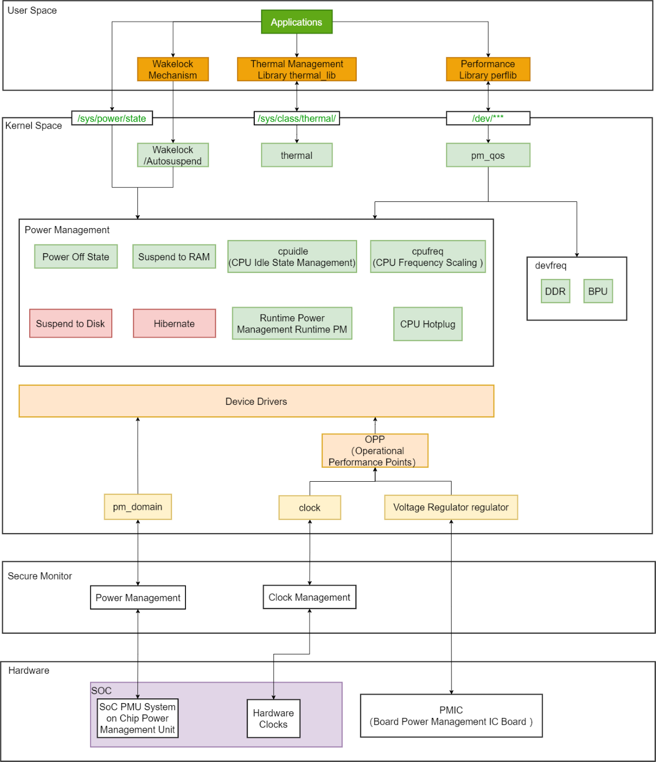
Key DVFS-related components in the diagram:
cpufreq Subsystem
cpufreqis the Linux kernel subsystem for CPU frequency scaling. It provides a unified interface for dynamic CPU frequency adjustment by kernel or user space.Frequency Drivers: Different platforms require different drivers (e.g.,
intel_pstatefor Intel,acpi-cpufreqfor ACPI systems).Governors: Strategies like
ondemand,conservative,performance,powersaveadjust frequency based on load.
cpuidle Subsystem
Manages CPU idle states. By placing CPUs into deeper idle states, power consumption is further reduced. Works with
cpufreq—when idle, frequency and voltage drop.devfreq Subsystem
Controls frequency of devices (e.g., GPU, memory). Allows devices to scale frequency based on load for power efficiency.
DVFS in Linux optimizes power and performance by adjusting frequency and voltage of CPU and other components. The kernel manages this via cpufreq, cpuidle, devfreq, while users can configure and optimize using tools and interfaces. Proper DVFS strategies allow Linux to reduce power without sacrificing performance.
DVFS Testing
As an example of temperature-based dynamic adjustment, test as follows:
Check current CPU thermal throttling threshold (default 95°C):
root@buildroot:~# cat /sys/devices/virtual/thermal/thermal_zone1/trip_point_1_temp
95000
Check the temperature and frequency information of the current system. You can see that the current CPU frequency is 1500MHz and 1200MHz, and the temperature is 45.7 ℃:
root@buildroot:~# hrut_somstatus
=====================1======================
temperature-->
        DDR: 46.9 (C)
        BPU: 45.6 (C)
        CPU: 45.7(C)
cpu frequency-->
              min(M) cur(M) max(M)
        cpu0: 300 1500 1500
        cpu1: 300 1200 1500
        cpu2: 300 300 1500
        cpu3: 300 1200 1500
        cpu4: 300 1200 1500
cpu5: 300 1200 1500
        cpu6: 300 1200 1500
        cpu7: 300 300 1500
bpu status information---->
              min(M) cur(M) max(M) ratio
        bpu0: 500 1000 1000 0
ddr frequency information---->
              min(M) cur(M) max(M)
        ddr: 266 4266 4266
GPU gc8000 frequency information---->
              min(M) cur(M) max(M)
        gc8000: 200 1000 1000
Set the CPU frequency modulation temperature threshold to 45°C to trigger the CPU frequency modulation mechanism:
echo 45000 > /sys/devices/virtual/thermal/thermal_zone1/trip_point_1_temp
Recheck status—CPU frequency drops to 300MHz, significantly reducing power:
root@buildroot:~# hrut_somstatus
=====================1=====================
temperature-->
        DDR      : 47.6 (C)
        BPU      : 46.4 (C)
        CPU      : 46.4 (C)
cpu frequency-->
              min(M)    cur(M)  max(M)
        cpu0    : 300   1500    1500
        cpu1    : 300   1200    1500
        cpu2    : 300   1200    1500
        cpu3    : 300   1200    1500
        cpu4    : 300   300     1500
        cpu5    : 300   1200    1500
        cpu6    : 300   1200    1500
        cpu7    : 300   1200    1500
bpu status information---->
              min(M)    cur(M)  max(M)  ratio
        bpu0    : 500   1000    1000    0
ddr frequency information---->
              min(M)    cur(M)  max(M)
        ddr     : 266   4266    4266
GPU gc8000 frequency information---->
              min(M)    cur(M)  max(M)
        gc8000  : 200   1000    1000
This demonstrates temperature-based DVFS. The system dynamically adjusts frequency in response to temperature, effectively managing power and preventing overheating. In practice, other components (BPU, DDR, GPU) can also scale frequency based on demand, further optimizing total power.
Note: When testing this function, you need to set a new temperature threshold based on the actual temperature of the current CPU. To trigger a DVFS response, the new threshold should be set lower than the current temperature value so that the system detects the temperature drop and adjusts the frequency accordingly.
Common DVFS Issues
Issue: System performance drops significantly after adjusting CPU frequency.
Solution: Verify the frequency is within supported range and avoid setting too low. Try different governors like
ondemandorschedutilfor dynamic load-based adjustment.- Issue: Graphics rendering problems occur after adjusting GPU frequency.Solution: Ensure that the GPU driver supports dynamic frequency scaling and that the adjusted frequency is within the GPU’s supported range. Additionally, verify that the GPU voltage matches the frequency setting to avoid rendering issues caused by insufficient voltage.
Issue: System responsiveness decreases after disabling CPU cores.
Solution: Configure CPU core enable/disable policies based on actual system workload. For example, enable more CPU cores under high load and disable some cores under low load. Also, use the
isolcpusparameter to bind critical tasks to specific CPU cores to maintain system responsiveness.
4.4.11.4. Suspend and Resume
Suspend and resume is another common low-power management mechanism, closely integrated with DVFS. When the system is idle, hardware components enter a sleep mode, turning off unnecessary power supplies to reduce power consumption. Upon an external event trigger, the system quickly wakes up, restores normal operation, and automatically adjusts frequency and voltage according to the current workload.
This system supports multiple sleep modes to reduce power consumption while enabling rapid recovery when needed. Currently supported wake-up sources include RTC wake-up, GPIO wake-up, and DSP voice wake-up.
Suspend and Resume Methods
Suspend Command
The suspend command is as follows:
echo mem > /sys/power/state
This command triggers the system to enter memory suspend (mem) mode. The system suspends all non-essential hardware and processes but retains the current memory state in physical RAM. Then, the processor and other hardware components are powered down to enter a low-power state. Typically, the system can be restored via external devices such as a button press.
Resume Commands
RTC Wake-up Command:
rtcwake -s 2 -m mem
-s: Sleep duration in seconds;-m: Suspend mode (e.g.,suspend to ram).
GPIO Wake-up:
Only AON GPIOs can serve as wake-up sources. For example, on the EVB, AON GPIO2 is used as the wake-up source. Pulling down AON GPIO2 wakes up the system. This GPIO must be configured as a wake-up source in the DTS.
Configure the AON GPIO as a wake-up source in the device tree (DTS) as follows:
	gpio-keys {
		compatible = "gpio-keys";
		autorepeat;
		pinctrl-names = "default";
		pinctrl-0 = <&aon_gpio_2>;

		key-power {
			debounce-interval = <100>;
			gpios = <&aon_gpio_porta 2 GPIO_ACTIVE_LOW>;
			label = "GPIO Key Power";
			linux,code = <KEY_POWER>;
			wakeup-source;
		};
	};
Pulling down AON GPIO2 will wake up the system. Users can configure the corresponding GPIO as a wake-up source based on their hardware design.
Porting and Development
Kernel Configuration
When porting the Linux kernel to a new hardware platform, ensure that kernel configuration enables features related to suspend and resume support. The following kernel configuration options are required:
CONFIG_SUSPEND: Enable system suspend support.
Users can use ./bd.sh boot menuconfig during compilation to select and configure these features.
Overview of Linux System Suspend / Resume Process
Linux system suspend mainly consists of two modes: Suspend and Hibernate. In Suspend mode, the system state is saved in memory (STR, Suspend to RAM), and hardware enters a low-power state. In Hibernate mode, the system state is saved to disk, and power is completely turned off; upon resume, the system state is loaded from disk.
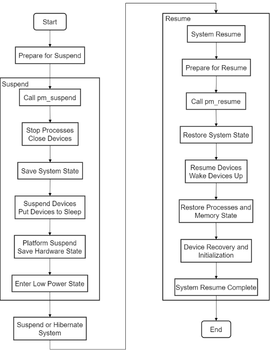
The basic steps of system suspend are as follows:
Prepare for Suspend:
Call the
pm_suspend()function to switch the system into suspend state.Before calling
pm_suspend(), the Linux kernel performs a series of preparations, such as stopping running processes and shutting down unnecessary devices.
Save System State:
The system calls
suspend_devices()to suspend all supported devices.Call
platform_suspend()to save platform-specific hardware states.
Enter Low-Power State:
Once all devices and system states are saved, the CPU enters a low-power state. At this point, most hardware is suspended, with only essential components (such as memory) remaining active.
Restore System State:
When the system resumes from suspend or hibernate,
resume_devices()is called to restore the state of all devices.The kernel restarts all processes and loads the system state from memory or disk, returning to the pre-suspend working state.
When the Linux system resumes from Suspend or Hibernate state, a series of steps are required to re-enable devices and restore previously saved states. The key to the resume process is loading the system’s operational state from the low-power state or disk, ensuring that devices and processes resume operation as expected.
The basic steps of the system resume process are as follows:
Prepare for Resume:
After the system resumes from a low-power state or disk, it first calls the
pm_resume()function to begin system recovery.Before calling
pm_resume(), the Linux kernel performs a series of preparations, such as reactivating required hardware and restoring system state.
Restore System State:
The system calls
resume_devices()to restore the state of all devices. This process restores device operation according to the device drivers.For Suspend mode, device states are saved in memory and thus restored from memory.
For Hibernate mode, the system reads the saved system state from disk and restores it to the pre-hibernation state.
Restore Process and Memory State:
After resuming from suspend or hibernate, the kernel restores the state of all processes, ensuring each process can continue execution from its paused state.
For hibernate mode, the kernel loads the process and memory state from the hibernation image on disk, restoring the system to its pre-hibernation state.
Device Recovery and Initialization:
The recovery process involves not only restoring memory and processes but also reinitializing all hardware devices. Specifically:
For hardware devices such as PCI and USB controllers, the system calls the device’s
resumemethod to re-enable them.Drivers ensure that hardware devices return to the correct operational state, such as re-enabling interrupts and resuming data transmission.
Resume Completion:
During the recovery process, all devices are restored to normal operation, memory data is recovered, and processes are restarted and continue execution.
After the system resumes, users can continue using the computer, and the system state is nearly identical to before the suspend.
The suspend and resume process of the system is illustrated below:
The Linux system suspend process involves three components: user-space applications, kernel space, and the Secure Monitor, which cooperate to complete the suspend operation. This process can be illustrated as follows:
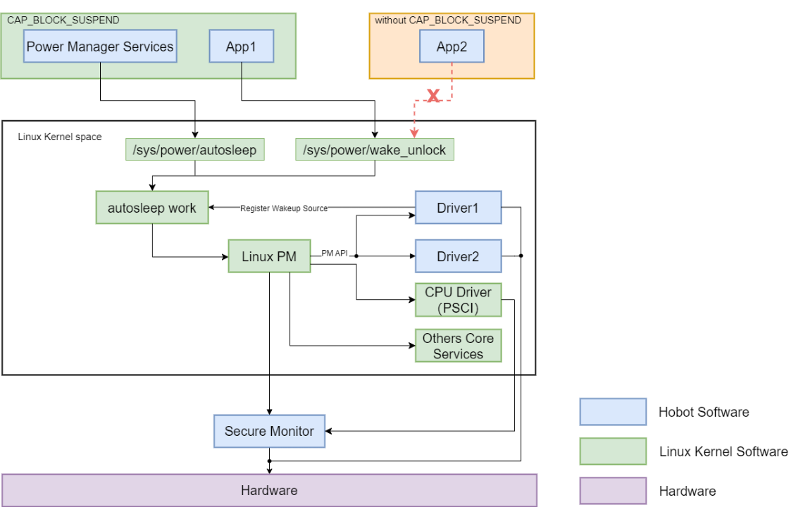
The power management workflow during suspend and resume in the above figure can be summarized as follows:
Applications interact with Linux PM through specific interfaces. Linux PM interacts with device drivers and core services via PM APIs, ultimately affecting the power state of the hardware.
The Secure Monitor plays a monitoring and protection role throughout the process, ensuring the security of power management.
The following is an explanation of each part in the figure:
Hobot Software (blue):
Power Manager Services: Software services responsible for managing power.
App1 and App2: Applications, where App2 does not have the
CAP_BLOCK_SUSPENDpermission and therefore cannot call the/sys/power/wake_unlockinterface.
Linux Kernel Software (green):
autosleep work: The automatic suspend mechanism, possibly used to automatically enter low-power states when the system is idle.
Linux PM (Power Management): The core power management module responsible for coordinating system power states.
Driver1 and Driver2: Device drivers, typically used to manage the power state of specific hardware.
CPU Driver (PSCI): CPU driver using the PSCI (Power State Coordination Interface) to manage CPU power states.
Others Core Services: Other core services, generally including system logging, security monitoring, etc.
Interfaces:
/sys/power/autosleep: Interface for setting or querying automatic suspend./sys/power/wake_unlock: Interface for unlocking wake-up sources; App2 cannot use it due to permission issues.
Secure Monitor:
Responsible for monitoring and managing hardware-level power states, ensuring system security and stability.
Hardware:
Underlying hardware that interacts with the software layer to implement power management functions.
System Suspend and Wake-up Testing
Perform GPIO sleep wake-up testing using the following test commands:
# Prepare to print logs
dmesg -w&
# System suspend
echo mem > /sys/power/state
After entering the above commands, the system will enter a suspended state. Pressing the wake-up button on the board will wake it up.
On the X5 EVB board, the location of the wake-up button can be referenced in the Functional Module Layout section under “Interface 6 Reset Function Button” (using EVB 1_b as an example).
After pressing the wake-up button to resume the system, the logs for the suspend and resume process are as follows:
root@buildroot:~# dmesg -w&
root@buildroot:~# echo mem > /sys/power/state
NOTICE:  mmu enabled from [LIGHT] sleep, pll: 1:1:1:1:1:0 relock: 0:0:0:0:0:0
[   69.484694] hobot_gmac 35010000.horizon_tsn eth0: mac_config_rx_queues_routing, not support packet mode :
[   69.644730] usb usb1: root hub lost power or was reset
[   69.644736] usb usb2: root hub lost power or was reset
[   69.928800] random: crng reseeded on system resumption
[   69.145044] PM: suspend entry (deep)
[   69.148213] Filesystems sync: 0.003 seconds
[   69.149837] Freezing user space processes
[   69.150455] remoteproc remoteproc0: clr: 866
[   69.150475] remoteproc remoteproc0: clr: 866,  0   866
[   69.151679] Freezing user space processes completed (elapsed 0.001 seconds)
[   69.151699] OOM killer disabled.
[   69.151707] Freezing remaining freezable tasks
[   69.153204] Freezing remaining freezable tasks completed (elapsed 0.001 seconds)
[   69.153223] printk: Suspending console(s) (use no_console_suspend to debug)
[   69.154767] HOBOT GDC 3d0c0000.gdc: hobot_gdc_suspend
[   69.154860] hobot-sif 3d050000.sif: cim_suspend
[   69.154874] hobot-sif 3d040000.sif: cim_suspend
[   69.154887] hobot-sif 3d030000.sif: cim_suspend
[   69.154900] hobot-sif 3d020000.sif: cim_suspend
[   69.154971] hobot_vpu_dev: [VPUDRV]vpu_suspend:7842: [-]vpu_suspend leave
[   69.154981] hobot_jpu_dev: [JPUDRV]jpu_suspend:3833: [+]jpu_suspend enter
[   69.154985] hobot_jpu_dev: [JPUDRV]jpu_suspend:3834: [-]jpu_suspend leave
[   69.195792] hobot-dsp dsp0: hobot_dsp_suspend dsp0
[   69.195884] vin mipi0: drivers/media/platform/horizon/camsys/mipi/hobot_mipi_host_ops.c:hobot_mipi_host_suspend_do enter suspend...
[   69.195893] vin mipi2: drivers/media/platform/horizon/camsys/mipi/hobot_mipi_host_ops.c:hobot_mipi_host_suspend_do enter suspend...
[   69.195900] vin mipi3: drivers/media/platform/horizon/camsys/mipi/hobot_mipi_host_ops.c:hobot_mipi_host_suspend_do enter suspend...
[   69.202999] CAM_SUBSYS soc:cam:cam_sys@0: camsys_suspend
[   69.203140] vin mipi1: drivers/media/platform/horizon/camsys/mipi/hobot_mipi_host_ops.c:hobot_mipi_host_suspend_do enter suspend...
[   69.203151] [INFO][HOBOT_OSD](hb_osd_suspend) done
[   69.203172] [CODEC_NODE]:[L731]hobot_codec_node_suspend 731
[   69.203281] PM: suspend devices took 0.050 seconds
[   69.205883] Disabling non-boot CPUs ...
[   69.206416] psci: CPU1 killed (polled 0 ms)
[   69.207251] psci: CPU2 killed (polled 0 ms)
[   69.208016] psci: CPU3 killed (polled 0 ms)
[   69.208612] psci: CPU4 killed (polled 0 ms)
[   69.209135] psci: CPU5 killed (polled 0 ms)
[   69.209687] psci: CPU6 killed (polled 0 ms)
[   69.211256] psci: CPU7 killed (polled 0 ms)
[   69.211484] Enabling non-boot CPUs ...
[   69.222647] Detected VIPT I-cache on CPU1
[   69.222707] GICv3: CPU1: found redistributor 100 region 0:0x0000000030160000
[   69.222741] CPU1: Booted secondary processor 0x0000000100 [0x412fd050]
[   69.223109] CPU1 is up
[   69.234201] Detected VIPT I-cache on CPU2
[   69.234235] GICv3: CPU2: found redistributor 200 region 0:0x0000000030180000
[   69.234259] CPU2: Booted secondary processor 0x0000000200 [0x412fd050]
[   69.234559] CPU2 is up
[   69.245647] Detected VIPT I-cache on CPU3
[   69.245679] GICv3: CPU3: found redistributor 300 region 0:0x00000000301a0000
[   69.245699] CPU3: Booted secondary processor 0x0000000300 [0x412fd050]
[   69.246028] CPU3 is up
[   69.257116] Detected VIPT I-cache on CPU4
[   69.257151] GICv3: CPU4: found redistributor 400 region 0:0x00000000301c0000
[   69.257174] CPU4: Booted secondary processor 0x0000000400 [0x412fd050]
[   69.257509] CPU4 is up
[   69.268597] Detected VIPT I-cache on CPU5
[   69.268645] GICv3: CPU5: found redistributor 500 region 0:0x00000000301e0000
[   69.268667] CPU5: Booted secondary processor 0x0000000500 [0x412fd050]
[   69.269009] CPU5 is up
[   69.280099] Detected VIPT I-cache on CPU6
[   69.280148] GICv3: CPU6: found redistributor 600 region 0:0x0000000030200000
[   69.280171] CPU6: Booted secondary processor 0x0000000600 [0x412fd050]
[   69.280538] CPU6 is up
[   69.291624] Detected VIPT I-cache on CPU7
[   69.291673] GICv3: CPU7: found redistributor 700 region 0:0x0000000030220000
[   69.291695] CPU7: Booted secondary processor 0x0000000700 [0x412fd050]
[   69.292097] CPU7 is up
[   69.306467] [CODEC_NODE]:[L751]hobot_codec_node_resume 751
[   69.306487] [INFO][HOBOT_OSD](hb_osd_resume) done
[   69.306494] vin mipi1: drivers/media/platform/horizon/camsys/mipi/hobot_mipi_host_ops.c:hobot_mipi_host_resume_do enter resume...
[   69.306575] CAM_SUBSYS soc:cam:cam_sys@0: camsys_resume
[   69.484694] hobot_gmac 35010000.horizon_tsn eth0: mac_config_rx_queues_routing, not support packet mode :\x02
[   69.484746] hobot_gmac 35010000.horizon_tsn eth0: configuring for phy/rgmii-id link mode
[   69.524503] vin mipi3: drivers/media/platform/horizon/camsys/mipi/hobot_mipi_host_ops.c:hobot_mipi_host_resume_do enter resume...
[   69.524512] vin mipi2: drivers/media/platform/horizon/camsys/mipi/hobot_mipi_host_ops.c:hobot_mipi_host_resume_do enter resume...
[   69.524518] vin mipi0: drivers/media/platform/horizon/camsys/mipi/hobot_mipi_host_ops.c:hobot_mipi_host_resume_do enter resume...
[   69.524826] hobot-dsp dsp0: hobot_dsp_resume dsp0
[   69.644730] usb usb1: root hub lost power or was reset
[   69.644736] usb usb2: root hub lost power or was reset
[   69.647123] hobot_jpu_dev: [JPUDRV]jpu_resume:3862: [+]jpu_resume enter
[   69.647129] hobot_jpu_dev: [JPUDRV]jpu_resume:3863: [-]jpu_resume leave
[   69.647137] hobot_vpu_dev: [VPUDRV]vpu_resume:7887: [+]vpu_resume enter
[   69.647141] hobot_vpu_dev: [VPUDRV]vpu_resume:8033: [-]vpu_resume leave
[   69.702201] hobot-sif 3d020000.sif: cim_resume
[   69.702213] hobot-sif 3d030000.sif: cim_resume
[   69.702224] hobot-sif 3d040000.sif: cim_resume
[   69.702234] hobot-sif 3d050000.sif: cim_resume
[   69.702299] HOBOT GDC 3d0c0000.gdc: hobot_gdc_resume
[   69.906154] PM: resume devices took 0.600 seconds
[   69.926659] OOM killer enabled.
[   69.926675] Restarting tasks ... done.
[   69.928800] random: crng reseeded on system resumption
[   69.934105] PM: suspend exit
[   69.968824] remoteproc remoteproc0: new: 866, 0   0
The following is a detailed analysis of the log:
Suspend Process
Entering Suspend:
echo mem > /sys/power/state: This command puts the system into suspend mode, specifically “deep sleep”.PM: suspend entry: The system begins entering the suspend state.
File System Sync:
Filesystems sync: 0.003 seconds: Before entering suspend, the system synchronizes the file system to ensure all data is written to disk.
Freezing User Space Processes:
Freezing user space processes: The system freezes user space processes to prevent state changes during suspend.Freezing user space processes completed (elapsed 0.001 seconds): The freezing process is complete.
Disabling Non-Boot CPUs:
Disabling non-boot CPUs ...: The system disables non-boot CPUs (all except the boot CPU) to save power.
Device Suspend
Device Suspend:
Multiple device suspend operations are logged, e.g.:
hobot_gdc_suspend,cim_suspend,vpu_suspend,jpu_suspend, etc., indicating these devices are suspended upon entering sleep.
PM: suspend devices took 0.050 seconds: The device suspend operation took 50 milliseconds.
Resume Process
Resuming Devices:
PM: resume devices took 0.600 seconds: The device resume process took 600 milliseconds.Log entries indicate multiple devices (e.g.,
hobot_gdc_resume,cim_resume,vpu_resume,jpu_resume) are reactivated.
Re-enabling Non-Boot CPUs:
Enabling non-boot CPUs ...: The system re-enables previously disabled non-boot CPUs.Logs show startup messages for each CPU (e.g.,
CPU1 is up), indicating successful recovery.
Other Events
USB Device Status:
usb usb1: root hub lost power or was reset: The USB root hub lost power or was reset during suspend/resume, which may affect USB device operation.
Random Number Generator:
random: crng reseeded on system resumption: Upon system resume, the cryptographically secure random number generator is reseeded, a security measure.
OOM Killer:
OOM killer disabledandOOM killer enabled: The OOM (Out Of Memory) killer is disabled during suspend to prevent process termination under low memory, and re-enabled upon resume.
Common Suspend/Resume Issues
Issue: System fails to wake up normally after suspend.
Solution: Check that wake-up source configurations are correct—for example, verify RTC wake-up settings and ensure GPIO pins used for wake-up are properly configured as wake-up sources. Also, examine system logs for error messages or anomalies during suspend and resume.
Issue: System performance degrades after wake-up.
Solution: After system wake-up, check the status of devices and drivers to ensure they have properly resumed operation. Consider adjusting suspend/resume strategies—such as using different suspend modes or modifying sleep durations—to minimize performance impact.
4.4.11.5. Typical Scenario Power Consumption
Using the X5 EVB motherboard as an example, the following are typical application scenario power consumption data:
Hardware Environment: X5 EVB motherboard
Workload Scenario:
8x CPU @ 1.5GHz, 80% load
1x BPU @ 1.0GHz, 80% load
LPDDR4 @ 3200MHz, 100% bandwidth
Dual camera input, 2x 1080p @ 30fps
Test Method:
Under 85°C junction temperature, average current data from each power rail of the X5 chip is recorded
Test Results:
Maximum average power consumption of the X5 chip is 4335mW
| Voltage Domains | Voltage(V) | Avg Current(mA) | Avg Power(mW) |
|---|---|---|---|
| CH0 SOC_1V8 | 1.8 | 16 | 28.8 |
| CH1 DDR_0V8 | 0.8 | 817 | 653.6 |
| CH2 GPU_0V8 | 0.8 | 0 | 0 |
| CH3 SOC_0V8 | 0.8 | 992 | 793.6 |
| CH4 DSP_0V8 | 0.8 | 80 | 64 |
| CH5 18_DSP | 1.8 | 4 | 7.2 |
| CH6 CSI_0V8 | 0.8 | 4 | 3.2 |
| CH7 SOC_3V3 | 3.3 | 0 | 0 |
| CH8 DSI_0V8 | 0.8 | 0 | 0 |
| CH9 AON_0V8 | 0.8 | 7 | 5.6 |
| CH10 AON_1V8 | 1.8 | 0 | 0 |
| CH11 18_SOC | 1.8 | 40 | 72 |
| CH12 USB_3V3 | 3.3 | 28 | 92.4 |
| CH13 CSI_1V8 | 1.8 | 4 | 7.2 |
| CH14 USB_0V8 | 0.8 | 28 | 22.4 |
| CH15 BPU_0V8 | 0.8 | 1033 | 826.4 |
| CH16 DDR_1V1 | 1.1 | 639 | 702.9 |
| CH17 CPU_0V8 | 0.8 | 1295 | 1036 |
| CH18 VDDA_1V | 1.8 | 4 | 7.2 |
| CH19 DDR_PLL | 1.8 | 4 | 7.2 |
| CH20 DSI_1V8 | 1.8 | 0 | 0 |
| CH21 ADC_1V8 | 1.8 | 3 | 5.4 |
| Total Power | 4335.1 |
Note:
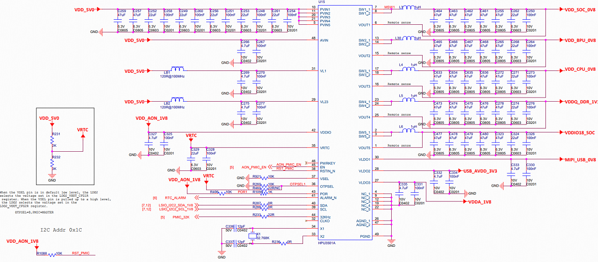
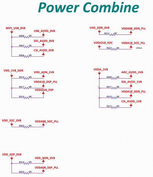
The power domains listed in the table above can be located on the X5 EVB schematic in the PMIC and Power Combine sections. Users can insert a current probe into the corresponding circuit to measure current and power consumption.