4.3.13. Watchdog Driver Debug Guide
4.3.13.1. Watchdog Overview
A watchdog (Watchdog Timer or Watchdog) is a hardware or software mechanism used to monitor the health status of a computer system. Its primary purpose is to ensure that the system can automatically recover in abnormal situations (e.g., hanging or crashing), preventing the system from remaining unresponsive for extended periods and ensuring system reliability. The watchdog mechanism typically includes a timer that automatically restarts the system or performs other recovery actions if the system fails to send a “heartbeat” signal within a specified time.
In the chip, the watchdog is a slave device on the APB (Advanced Peripheral Bus).
4.3.13.2. Watchdog Features
The watchdog in the chip has the following features:
APB3 Interface Support: Compatible with the APB3 interface.
Countdown Timeout Indication: The counter counts down from a preset value to 0, indicating a timeout.
System Reset Trigger: If the interrupt is not cleared before a second timeout occurs, a system reset will be triggered.
Programmable Timeout Range: Provides a programmable timeout period range; the value can be hard-coded during configuration to reduce register requirements.
Dual Programmable Timeout Periods: Optional dual programmable timeout periods, suitable for cases where the initial startup wait time differs from subsequent startup wait times; these values can be hard-coded.
Reset Pulse Length Setting: Supports programmable and hard-coded reset pulse lengths.
Prevents Accidental Restart: Prevents accidental restart of the DW_apb_wdt counter.
Prevents Accidental Disable: Prevents accidental disabling of DW_apb_wdt.
Pause Mode Support: Optionally supports pause mode, implemented via an external pause enable signal.
Test Mode Signal: A test mode signal used to reduce the time required for functional testing.
4.3.13.3. Functional Description
Typical Applications of Watchdog
A watchdog is a mechanism used to monitor the system’s operational status, capable of automatically restarting the system when faults or system hangs occur. In Linux systems, a typical application of the watchdog is to ensure that the system can automatically restart when encountering deadlocks, hangs, or other unrecoverable failures, thereby restoring normal operation.
The figure below illustrates a typical application scenario where the watchdog resets the system from a deadlock state:
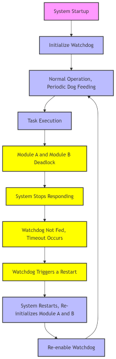
Specific explanation as follows:
Under normal conditions:
The system operates normally, and the watchdog is fed periodically.
Tasks complete without deadlocks, and the watchdog timer continues counting without triggering a restart.
After a deadlock occurs:
Module A and Module B enter a deadlock, causing the system to become unresponsive.
Due to the deadlock, the system cannot complete periodic tasks and thus fails to feed the watchdog in time.
The watchdog times out and triggers a restart.
After system restart:
The system restarts, initializing Module A and B, eliminating the deadlock.
The watchdog begins counting again, continuing to monitor the system status.
Watchdog Functional Principle
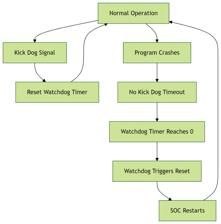
At its core, a watchdog is essentially a timer. It generally has an input referred to as “kicking the dog” or “servicing the dog.” When the SoC is operating normally, it outputs a signal to the watchdog at regular intervals to reset the watchdog timer. If no signal is sent within a specified period (typically when the program runs out of control), the watchdog timer counts down to 0, triggering a timeout event. The watchdog then sends a reset signal to the SoC, causing the system to restart. The purpose of the watchdog is to prevent system crashes caused by runaway programs.
The functional block diagram of the watchdog is shown below:
Watchdog Operation Modes
The primary task of the watchdog is to monitor the system’s operational status, preventing the system from failing to self-recover due to software faults, deadlocks, or other anomalies. It achieves this through periodic timing, timeout detection, and reset triggering.
Common operating modes of the watchdog include:
Normal Mode: Software periodically resets the Watchdog timer. If no “feed” signal is received within the specified time, the Watchdog triggers a reset.
Debug Mode: The Watchdog can be paused during debugging to avoid unintended resets. Typically, an external signal or special control command is required to activate debug mode.
Reset Protection Mode: When a fault is detected, the Watchdog triggers a system reset, but this reset process is protected to prevent unnecessary operations from causing frequent system restarts.
Basic Workflow of Watchdog
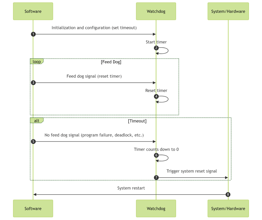
The core mechanism of the watchdog operation is “timer timeout” and “reset”:
Initialization and Configuration: During system startup, the watchdog is initialized and configured. The system sets the timeout duration (i.e., the countdown cycle of the Watchdog timer), usually set by software, but can also be hard-coded. At this point, the watchdog begins counting.
“Feeding the Dog” Mechanism: Under normal conditions, the software program in the system periodically sends a signal to the watchdog, known as a “feed” operation. This is typically achieved by resetting the watchdog timer. For example, software writes a specific value to the watchdog at regular intervals, resetting the countdown process to ensure the watchdog does not time out.
Timeout Detection: If the software program fails to perform a “feed” operation for an extended period (e.g., due to a program deadlock, crash, or hang), the watchdog timer counts down to the preset timeout value (usually several seconds to minutes).
Post-Timeout Handling: When the timer counts down to 0, the watchdog assumes the system is abnormal and automatically triggers a predefined response, typically a reset operation, restarting the system or hardware modules to restore the system to a normal state.
The above mechanism can be illustrated as follows:
Details of Watchdog Operation
Normal Operation Mode During normal operation, the watchdog periodically receives “feed” signals from the software. Each time the software triggers a “feed,” the watchdog’s timer is reset and begins counting anew. If the watchdog does not receive a “feed” signal within the timer cycle, it detects a timeout and triggers a reset, restarting the system.
Timeout Handling
Timeout Condition: If the watchdog does not receive a “feed” signal within the set timeout period, it indicates a potential system fault (e.g., program deadlock, infinite loop, etc.).
Reset After Timeout: The watchdog triggers a system reset. This is typically a hardware-level reset operation, restarting the entire system or specific hardware modules (such as CPU, peripherals, etc.), clearing the current error state to ensure the system can continue running.
Configuration and Programmability
Timeout Duration (Period): The watchdog’s timeout duration is typically configurable. Developers can set an appropriate timeout based on requirements; shorter periods are suitable for systems with high real-time demands, while longer periods are suitable for systems less sensitive to response times.
Dual Timeout Periods: Some watchdogs support configuring different timeout periods, such as different timeouts for the startup phase versus normal operation. The startup phase usually requires a longer wait time, while the timeout period during normal operation can be shorter.
Hard-Coded Configuration: To reduce frequent register access, some watchdogs allow configuration values to be hard-coded into hardware, reducing system complexity and resource consumption.
Prevention of Misoperation
Preventing Watchdog Disable: To prevent software errors or malicious code from disabling the watchdog, some watchdog systems provide “protection mechanisms,” such as requiring a specific security sequence to disable the watchdog or enforcing watchdog enablement under certain conditions (e.g., debug mode).
Preventing Restart: Some watchdog implementations include protective measures to prevent the system from repeatedly restarting without authorization or necessity. For example, additional “reset protection” mechanisms can be used in hardware design to prevent frequent resets.
External Control and Pause
External Pause Signal: Some watchdogs allow an external signal to pause the watchdog timer, which is useful for debugging or pausing the watchdog under special circumstances. The external signal can control whether the watchdog continues counting, avoiding unintended resets during debugging.
Pause Mode: Under specific conditions, the watchdog can be configured to enter pause mode, during which the watchdog will not trigger a reset until the system resumes normal operation.
Test Mode
Functional Testing: During development and verification, the watchdog typically provides a test mode to simulate timeout and reset behaviors. This helps developers verify that the watchdog functions correctly under expected conditions.
4.3.13.4. Watchdog Driver Code Description
Watchdog DTS Configuration
The device tree definition for the watchdog controller in the chip is located in the arch/arm64/boot/dts/hobot/x5.dtsi file within the kernel folder of the BSP source package:
a55_apb1 {
    ……
    watchdog: watchdog@34250000 {
        compatible = "snps,dw-wdt";
        status = "okay";
        reg = <0x34250000 0x10000>;
        clocks = <&hpsclks X5_WDT_PCLK>;
        interrupt-parent = <&gic>;
        interrupts = <GIC_SPI 71 IRQ_TYPE_LEVEL_HIGH>;
        timeout-sec = <10>;
        clk-rate-div = <2>;
        resets = <&socrst SOC_WDT_APB_RESET>;
    };
It can be seen that the watchdog is a device mounted on the a55_apb1 bus of the chip. Below is a detailed explanation of the meaning of each field in this device tree:
watchdog:
watchdog: watchdog@34250000:watchdog: This is the label of the device, which can be referenced.watchdog@34250000: This is the device address; in the device tree, this represents the base address of the device.34250000is the physical address of the device in system memory.
compatible:
compatible = "snps,dw-wdt";This is a device compatibility descriptor used to indicate which hardware the driver should match. Here,
"snps,dw-wdt"indicates that the device is adw-wdt(DesignWare Watchdog Timer) provided by Synopsys™, telling the operating system to use a compatible driver to manage this hardware device.
status:
status = "okay";This field indicates the device’s status.
"okay"means the device is enabled and can be used by the kernel. If this field is"disabled", it means the device is disabled in the kernel.
reg:
reg = <0x34250000 0x10000>;This field specifies the register range of the device.
0x34250000is the base address of the device, and0x10000indicates the address range of the device (register size is 0x10000 bytes). This tells the kernel how to map the hardware registers.
clocks:
clocks = <&hpsclks X5_WDT_PCLK>;This field specifies the clock source on which the device depends.
&hpsclksis a reference to the clock controller node, andX5_WDT_PCLKis a specific clock source. The kernel will configure the device clock based on this information.
interrupt-parent:
interrupt-parent = <&gic>;This field specifies the device’s interrupt controller. In this example,
&gicindicates that the device uses the GIC (Generic Interrupt Controller). This allows the operating system to correctly configure device interrupts.
interrupts:
interrupts = <GIC_SPI 71 IRQ_TYPE_LEVEL_HIGH>;This field specifies the device’s interrupt information.
GIC_SPIindicates a shared external interrupt,71is the interrupt number of the device, andIRQ_TYPE_LEVEL_HIGHindicates that the interrupt is level-triggered high.
timeout-sec:
timeout-sec = <10>;This field specifies the watchdog timer’s timeout duration (unit: seconds). In this example,
10means the timer’s timeout duration is 10 seconds. If the system does not respond within this time (e.g., fails to reset the watchdog timer), the watchdog will trigger a system restart.
clk-rate-div:
clk-rate-div = <2>;This field indicates the clock frequency division factor. On some hardware platforms, the timer clock is based on a higher-frequency clock signal, and the division factor determines the actual frequency of the clock signal. Here,
2means the clock frequency will be divided by 2.
resets:
resets = <&socrst SOC_WDT_APB_RESET>;This field specifies the reset control signal associated with the device. In this example,
&socrstis a node reference to the reset controller, andSOC_WDT_APB_RESETis the reset signal for the device. This is used to control the device’s reset operation.
Note: Nodes in x5.dtsi mainly declare SoC common characteristics and are unrelated to specific circuit boards; generally, they should not be modified.
The chip’s watchdog controller is enabled by default. If you need to disable the watchdog device on specific hardware, add the following node to the corresponding dts file:
&watchdog {
    status = "disabled";
};
Watchdog Kernel Configuration
The watchdog device is enabled by default, but whether the watchdog timer is automatically started at kernel power-on is controlled by HORIZON_WATCHDOG_ENABLE.
By default, in the debug version, the watchdog device is registered, but the timer is not enabled. It can be debugged and verified through the kernel standard Watchdog character device in user space:
/* arch/arm64/configs/hobot_x5_soc_defconfig */
CONFIG_WATCHDOG=y
CONFIG_DW_WATCHDOG=y
By default, in the perf version, the watchdog device is registered, and the timer will be enabled:
/* arch/arm64/configs/hobot_x5_soc_perf_defconfig */
...
CONFIG_WATCHDOG=y
CONFIG_DW_WATCHDOG=y
CONFIG_HORIZON_WATCHDOG_ENABLE=y
...
The CONFIG_HORIZON_WATCHDOG_ENABLE configuration affects whether the watchdog timer starts in the code. The relevant code is in kernel/drivers/watchdog/dw_wdt.c:
static int dw_wdt_drv_probe(struct platform_device *pdev)
{
    ……
#ifdef CONFIG_HORIZON_WATCHDOG_ENABLE
    dw_wdt->wdt_disable = 0;
#else
    dw_wdt->wdt_disable = 1;
#endif
4.3.13.5. Watchdog Function Usage
Watchdog Register Description
The source code uses macro definitions to describe the registers used by the watchdog driver:
#define WDOG_CONTROL_REG_OFFSET		    0x00
#define WDOG_CONTROL_REG_WDT_EN_MASK	    0x01
#define WDOG_CONTROL_REG_RESP_MODE_MASK	    0x02
#define WDOG_TIMEOUT_RANGE_REG_OFFSET	    0x04
#define WDOG_TIMEOUT_RANGE_TOPINIT_SHIFT    4
#define WDOG_CURRENT_COUNT_REG_OFFSET	    0x08
#define WDOG_COUNTER_RESTART_REG_OFFSET     0x0c
#define WDOG_COUNTER_RESTART_KICK_VALUE	    0x76
#define WDOG_INTERRUPT_STATUS_REG_OFFSET    0x10
#define WDOG_INTERRUPT_CLEAR_REG_OFFSET     0x14
#define WDOG_COMP_PARAMS_5_REG_OFFSET       0xe4
#define WDOG_COMP_PARAMS_4_REG_OFFSET       0xe8
#define WDOG_COMP_PARAMS_3_REG_OFFSET       0xec
#define WDOG_COMP_PARAMS_2_REG_OFFSET       0xf0
#define WDOG_COMP_PARAMS_1_REG_OFFSET       0xf4
#define WDOG_COMP_PARAMS_1_USE_FIX_TOP      BIT(6)
#define WDOG_COMP_VERSION_REG_OFFSET        0xf8
#define WDOG_COMP_TYPE_REG_OFFSET           0xfc

/* There are sixteen TOPs (timeout periods) that can be set in the watchdog. */
#define DW_WDT_NUM_TOPS		16
#define DW_WDT_FIX_TOP(_idx)	(1U << (16 + _idx))

#define DW_WDT_DEFAULT_SECONDS	30
Below are the specific functions of these macro definitions:
| Macro Definition Name | Value | Description |
|---|---|---|
WDOG_CONTROL_REG_OFFSET |
0x00 |
Offset of the control register. |
WDOG_CONTROL_REG_WDT_EN_MASK |
0x01 |
Mask used to enable the watchdog. |
WDOG_CONTROL_REG_RESP_MODE_MASK |
0x02 |
Mask used to set the watchdog response mode. |
WDOG_TIMEOUT_RANGE_REG_OFFSET |
0x04 |
Offset of the timeout range register. |
WDOG_TIMEOUT_RANGE_TOPINIT_SHIFT |
4 |
Bit shift for TOP initialization in the timeout range register. |
WDOG_CURRENT_COUNT_REG_OFFSET |
0x08 |
Offset of the current count register. |
WDOG_COUNTER_RESTART_REG_OFFSET |
0x0c |
Offset of the counter restart register. |
WDOG_COUNTER_RESTART_KICK_VALUE |
0x76 |
Value written to restart the counter. |
WDOG_INTERRUPT_STATUS_REG_OFFSET |
0x10 |
Offset of the interrupt status register. |
WDOG_INTERRUPT_CLEAR_REG_OFFSET |
0x14 |
Offset of the interrupt clear register. |
WDOG_COMP_PARAMS_5_REG_OFFSET |
0xe4 |
Offset of component parameter register 5. |
WDOG_COMP_PARAMS_4_REG_OFFSET |
0xe8 |
Offset of component parameter register 4. |
WDOG_COMP_PARAMS_3_REG_OFFSET |
0xec |
Offset of component parameter register 3. |
WDOG_COMP_PARAMS_2_REG_OFFSET |
0xf0 |
Offset of component parameter register 2. |
WDOG_COMP_PARAMS_1_REG_OFFSET |
0xf4 |
Offset of component parameter register 1. |
WDOG_COMP_PARAMS_1_USE_FIX_TOP |
BIT(6) |
Bit 6 in component parameter register 1, indicating whether fixed TOP functionality is used. |
WDOG_COMP_VERSION_REG_OFFSET |
0xf8 |
Offset of the component version register. |
WDOG_COMP_TYPE_REG_OFFSET |
0xfc |
Offset of the component type register. |
DW_WDT_NUM_TOPS |
16 |
Number of timeout periods (TOPs) supported by the watchdog. |
DW_WDT_FIX_TOP(_idx) |
1U << (16 + _idx) |
Macro used to generate fixed TOP values. |
DW_WDT_DEFAULT_SECONDS |
30 |
Default timeout duration of the watchdog (seconds). |
Watchdog Driver Key Structure Descriptions
dw_wdt_rmod
enum dw_wdt_rmod {
    DW_WDT_RMOD_RESET = 1,
    DW_WDT_RMOD_IRQ = 2
};
This dw_wdt_rmod enumeration type is used to represent different response modes of the watchdog device (dw_wdt). Its members are described as follows:
DW_WDT_RMOD_RESET: Value 1, indicating that when the watchdog times out, the device will trigger a system reset.DW_WDT_RMOD_IRQ: Value 2, indicating that when the watchdog times out, the device will generate an interrupt (IRQ) instead of resetting the system.
Usage scenarios:
System Reset: In some cases, if the system encounters a severe error or unrecoverable state, setting the
DW_WDT_RMOD_RESETmode causes the watchdog to reset the system upon timeout, attempting to restore normal operation.Interrupt Generation: In other cases, if finer control or handling of timeout events is required, setting the
DW_WDT_RMOD_IRQmode causes the watchdog to generate an interrupt upon timeout, allowing system software to handle the interrupt and perform corresponding error handling or logging operations.
dw_wdt_timeout
struct dw_wdt_timeout {
    u32 top_val;
    unsigned int sec;
    unsigned int msec;
};
The dw_wdt_timeout structure is used to represent the timeout period parameters of the watchdog device (dw_wdt). Its members are described as follows:
top_val: An unsigned 32-bit integer used to store a value related to the timeout period, typically associated with settings in hardware registers. In the watchdog device,top_valrepresents specific timeout period values (TOPs) used to configure the watchdog’s timeout behavior.sec: An unsigned integer representing the seconds portion of the timeout period.msec: An unsigned integer representing the milliseconds portion of the timeout period.
dw_wdt
struct dw_wdt {
    void __iomem		*regs;
    struct clk		*clk;
    struct clk		*pclk;
    unsigned long		rate;
    enum dw_wdt_rmod	rmod;
    struct dw_wdt_timeout	timeouts[DW_WDT_NUM_TOPS];
    struct watchdog_device	wdd;
    struct reset_control	*rst;
    /* Save/restore */
    u32			control;
    u32			timeout;
#if IS_ENABLED(CONFIG_ARCH_HOBOT_X5)
    u32			clk_rate_div;
    u32			wdt_disable;
#endif

#ifdef CONFIG_DEBUG_FS
    struct dentry		*dbgfs_dir;
#endif
};
The dw_wdt structure is used to describe the watchdog device. Its members are described as follows:
regs: A pointer to the device registers, used for direct access to hardware registers.clkandpclk: Represent the watchdog timer clock and APB bus clock, respectively, used to obtain clock frequency and control clock enable/disable.rate: Represents the clock frequency of the watchdog timer.rmod: Represents the watchdog’s response mode, which can be reset (DW_WDT_RMOD_RESET) or interrupt (DW_WDT_RMOD_IRQ).timeouts: An array storing values for different timeout periods, allowing the watchdog to have multiple timeout options.wdd: A structure used to interact with the Linux kernel’s watchdog framework.rst: A pointer to the reset control structure, used to perform reset operations related to the watchdog.controlandtimeout: Used to save the current values of the watchdog control register and timeout period, so they can be restored when needed.clk_rate_divandwdt_disable: Members specific to the HOBOT_X5 architecture, used for clock frequency division and disabling the watchdog.dbgfs_dir: WhenCONFIG_DEBUG_FSis configured, used to create directory entries in the debugfs file system for debugging purposes.
This structure is the core data structure of the watchdog driver, containing all necessary information to manage the hardware watchdog. Initialization, configuration, operation, and cleanup functions of the driver will use this structure.
Watchdog Driver Interface Functions
Below are descriptions of the interface functions related to the watchdog driver in the source code:
dw_wdt_is_enabled(struct dw_wdt *dw_wdt):Parameter:
dw_wdt- A pointer to thedw_wdtstructure, representing an instance of the watchdog device.Function: Checks whether the watchdog device is already enabled.
dw_wdt_update_mode(struct dw_wdt *dw_wdt, enum dw_wdt_rmod rmod):Parameters:
dw_wdt- A pointer to thedw_wdtstructure.rmod- The new response mode, which can beDW_WDT_RMOD_RESETorDW_WDT_RMOD_IRQ.
Function: Updates the response mode of the watchdog device.
dw_wdt_find_best_top(struct dw_wdt *dw_wdt, unsigned int timeout, u32 *top_val):Parameters:
dw_wdt- A pointer to thedw_wdtstructure.timeout- The requested timeout duration (in seconds).top_val- A pointer to a variable that will store the best TOP value.
Function: Finds the most suitable timeout period (TOP) value.
dw_wdt_get_min_timeout(struct dw_wdt *dw_wdt):Parameter:
dw_wdt- A pointer to thedw_wdtstructure.Function: Retrieves the minimum timeout duration of the watchdog device.
dw_wdt_get_max_timeout_ms(struct dw_wdt *dw_wdt):Parameter:
dw_wdt- A pointer to thedw_wdtstructure.Function: Retrieves the maximum timeout duration of the watchdog device (in milliseconds).
dw_wdt_get_timeout(struct dw_wdt *dw_wdt):Parameter:
dw_wdt- A pointer to thedw_wdtstructure.Function: Retrieves the current timeout duration of the watchdog device.
dw_wdt_ping(struct watchdog_device *wdd):Parameter:
wdd- A pointer to thewatchdog_devicestructure.Function: Refreshes the timer of the watchdog device.
dw_wdt_set_timeout(struct watchdog_device *wdd, unsigned int top_s):Parameters:
wdd- A pointer to thewatchdog_devicestructure.top_s- The requested timeout duration (in seconds).
Function: Sets the timeout duration of the watchdog device.
dw_wdt_set_pretimeout(struct watchdog_device *wdd, unsigned int req):Parameters:
wdd- A pointer to thewatchdog_devicestructure.req- The requested pre-timeout duration.
Function: Sets the pre-timeout feature.
dw_wdt_arm_system_reset(struct dw_wdt *dw_wdt):Parameter:
dw_wdt- A pointer to thedw_wdtstructure.Function: Configures and enables the watchdog device so that it triggers a system reset upon timeout.
dw_wdt_start(struct watchdog_device *wdd):Parameter:
wdd- A pointer to thewatchdog_devicestructure.Function: Starts the watchdog device.
dw_wdt_stop(struct watchdog_device *wdd):Parameter:
wdd- A pointer to thewatchdog_devicestructure.Function: Stops the watchdog device.
dw_wdt_restart(struct watchdog_device *wdd, unsigned long action, void *data):Parameters:
wdd- A pointer to thewatchdog_devicestructure.action- The restart action.data- Restart data.
Function: Restarts the watchdog device.
dw_wdt_get_timeleft(struct watchdog_device *wdd):Parameter:
wdd- A pointer to thewatchdog_devicestructure.Function: Retrieves the remaining time of the watchdog device.
dw_wdt_irq(int irq, void *devid):Parameters:
irq- The interrupt number.devid- A pointer to the device instance.
Function: The interrupt handler function for the watchdog device.
dw_wdt_suspend(struct device *dev):Parameter:
dev- A pointer to thedevicestructure.Function: Suspends the watchdog device.
dw_wdt_resume(struct device *dev):Parameter:
dev- A pointer to thedevicestructure.Function: Resumes the watchdog device.
dw_wdt_handle_tops(struct dw_wdt *dw_wdt, const u32 *tops):Parameters:
dw_wdt- A pointer to thedw_wdtstructure.tops- A pointer to the array of TOPs.
Function: Handles and sorts the array of timeout periods (TOPs).
dw_wdt_init_timeouts(struct dw_wdt *dw_wdt, struct device *dev):Parameters:
dw_wdt- A pointer to thedw_wdtstructure.dev- A pointer to thedevicestructure.
Function: Initializes the timeout periods of the watchdog device.
dw_wdt_dbgfs_init(struct dw_wdt *dw_wdt):Parameter:
dw_wdt- A pointer to thedw_wdtstructure.Function: Initializes the debugfs interface.
dw_wdt_dbgfs_clear(struct dw_wdt *dw_wdt):Parameter:
dw_wdt- A pointer to thedw_wdtstructure.Function: Clears the debugfs interface.
dw_wdt_drv_probe(struct platform_device *pdev):Parameter:
pdev- A pointer to theplatform_devicestructure.Function: Initializes the platform device driver.
dw_wdt_drv_remove(struct platform_device *pdev):Parameter:
pdev- A pointer to theplatform_devicestructure.Function: Unloads the platform device driver.
Watchdog Testing
Note: Before performing watchdog testing, the watchdog timer function must be enabled, i.e., CONFIG_HORIZON_WATCHDOG_ENABLE must be enabled. Then, recompile the kernel image and flash the new kernel image before testing.
# Reconfigure the kernel config file to enable CONFIG_HORIZON_WATCHDOG_ENABLE
./bd.sh boot menuconfig
# Recompile the kernel image
./bd.sh boot
Watchdog debugfs
In the watchdog function interface, several functions related to debugfs can be seen, with the following prototypes:
static const struct debugfs_reg32 dw_wdt_dbgfs_regs[] = {
    DW_WDT_DBGFS_REG("cr", WDOG_CONTROL_REG_OFFSET),
    DW_WDT_DBGFS_REG("torr", WDOG_TIMEOUT_RANGE_REG_OFFSET),
    DW_WDT_DBGFS_REG("ccvr", WDOG_CURRENT_COUNT_REG_OFFSET),
    DW_WDT_DBGFS_REG("crr", WDOG_COUNTER_RESTART_REG_OFFSET),
    DW_WDT_DBGFS_REG("stat", WDOG_INTERRUPT_STATUS_REG_OFFSET),
    DW_WDT_DBGFS_REG("param5", WDOG_COMP_PARAMS_5_REG_OFFSET),
    DW_WDT_DBGFS_REG("param4", WDOG_COMP_PARAMS_4_REG_OFFSET),
    DW_WDT_DBGFS_REG("param3", WDOG_COMP_PARAMS_3_REG_OFFSET),
    DW_WDT_DBGFS_REG("param2", WDOG_COMP_PARAMS_2_REG_OFFSET),
    DW_WDT_DBGFS_REG("param1", WDOG_COMP_PARAMS_1_REG_OFFSET),
    DW_WDT_DBGFS_REG("version", WDOG_COMP_VERSION_REG_OFFSET),
    DW_WDT_DBGFS_REG("type", WDOG_COMP_TYPE_REG_OFFSET)
};
``````c
static void dw_wdt_dbgfs_init(struct dw_wdt *dw_wdt)
{
    struct device *dev = dw_wdt->wdd.parent;
    struct debugfs_regset32 *regset;

    regset = devm_kzalloc(dev, sizeof(*regset), GFP_KERNEL);
    if (!regset)
        return;

    regset->regs = dw_wdt_dbgfs_regs;
    regset->nregs = ARRAY_SIZE(dw_wdt_dbgfs_regs);
    regset->base = dw_wdt->regs;

    dw_wdt->dbgfs_dir = debugfs_create_dir(dev_name(dev), NULL);

    debugfs_create_regset32("registers", 0444, dw_wdt->dbgfs_dir, regset);
}

static void dw_wdt_dbgfs_clear(struct dw_wdt *dw_wdt)
{
    debugfs_remove_recursive(dw_wdt->dbgfs_dir);
}
The purpose of these functions is to create a read-only node named registers (with permission 0444) in the Linux system’s debugfs. This allows convenient access via the debugfs interface to view the status of device registers (those included in the dw_wdt_dbgfs_regs array), aiding in debugging and analyzing the device’s operation.
Debug log example:
root@buildroot:/sys/kernel/debug/34250000.watchdog# cat registers
cr = 0x00000019
torr = 0x0000000e
ccvr = 0x29a5f5d9
crr = 0x00000000
stat = 0x00000000
param5 = 0x00000000
param4 = 0x00000000
param3 = 0x00000000
param2 = 0x0000ffff
param1 = 0x10001a50
version = 0x3131332a
type = 0x44570120
Watchdog Test Example
Below is a simple watchdog test example:
#include <stdio.h>
#include <stdlib.h>
#include <unistd.h>  // UNIX Standard Function Definitions
#include <sys/types.h>
#include <sys/stat.h>
#include <fcntl.h>  // file control definition
#include <termios.h>    // PPSIX terminal control definition
#include <errno.h>  // Error number definition
#include <pthread.h>
#include <linux/watchdog.h>
#include <string.h>
#include <sys/ioctl.h>

int watchdogfd;
int feeddog = 1;

void* feeddogthread()
{
    int feeddogvalue;
    int returnval;

    feeddogvalue = 65535;

    while (feeddog) {
        printf("feed dog\n");
        returnval = write(watchdogfd, &feeddogvalue, sizeof(int));
        sleep(5);  // Every 5 seconds, the value of the watchdog counter register will be reloaded
    }
}

void watchdog_demo_help() {
    printf("Usage: watchdog_program [option]\n");
    printf("Options:\n");
    printf("  h      Show this help message\n");
    printf("  g      Get the currently set watchdog timeout period\n");
    printf("  e      Exit the watchdog test program\n");
    printf("  t      Get the remaining time before the watchdog triggers timeout\n");
    printf("  r      Restart the watchdog\n");
    // Add more options here if necessary
}

int main()
{
    pthread_t watchdogThd;
    //int watchdogfd;
    int returnval;
    char readline[32], *p;

    // open watchdog device
    if ((watchdogfd = open("/dev/watchdog", O_RDWR|O_NONBLOCK)) < 0) {
        printf("cannot open the watchdog device\n");
        exit(0);
    }

    int timeout = 10;  // Warning! The value will be parsed as a hexadecimal number in ioctl.
    int timeleft;
    ioctl(watchdogfd, WDIOC_SETTIMEOUT, &timeout);
    printf("The watchdog timeout was set to %d seconds\n", timeout);

    // Creating a dog feeding thread
    returnval = pthread_create(&watchdogThd, NULL, feeddogthread, NULL);
    if (returnval < 0)
        printf("cannot create feeddog thread\n");

    while (1) {
        printf("Command (e quit): ");
        memset(readline, '\0', sizeof(readline));
        fgets(readline, sizeof(readline), stdin);

        /* Remove the first null character of a string */
        p = readline;
        while(*p == ' ' || *p == '\t')
                p++;

        switch(*p) {
        case 'h':
            watchdog_demo_help();  // Call help function to display options
            break;
        case 'g':
            ioctl(watchdogfd, WDIOC_GETTIMEOUT, &timeout);
            printf("The timeout was is %d seconds\n", timeout);
            break;
        case 'e':
            printf("Close watchdog and exit safely!\n");
            //write(watchdogfd, "V", 1);
            int disable_dog = WDIOS_DISABLECARD;
            ioctl(watchdogfd, WDIOC_SETOPTIONS, &disable_dog);
            close(watchdogfd);
            return 0;
        case 's':
            printf("stop feed dog\n");
            feeddog = 0;
            break;
        case 't':
            ioctl(watchdogfd, WDIOC_GETTIMELEFT, &timeleft);
            printf("The timeout was is %d seconds\n", timeleft);
            break;
        case 'r':
            printf("we don't close watchdog. The machine will reboot in a few seconds!\n");
            printf("wait......\n");
            break;
        default:
            printf("get error char: %c, it's an invalid option. Type 'h' for help.\n", *p);
        }
    }

    return 0;
}
This code operates the watchdog device /dev/watchdog to manage and interact with the watchdog, enabling command-line control over watchdog timeout, restart, and keep-alive (feeding) operations. The specific functionalities are as follows:
Open the Watchdog Device:
Opens
/dev/watchdogusingopen("/dev/watchdog", O_RDWR | O_NONBLOCK)to allow read and write access in non-blocking mode.
Set Watchdog Timeout:
Uses
ioctl(watchdogfd, WDIOC_SETTIMEOUT, &timeout)to set the watchdog timeout, defaulting to 10 seconds. If not fed before timeout, the system will reboot.
Keep-Alive (Feeding) Thread:
Creates a thread named
feeddogthreadthat writes a value (65535) to the watchdog device every 5 seconds to “feed” the watchdog and prevent system reboot due to timeout.
User Interaction Commands:
The main thread provides a simple command-line interface to accept user input. Supported commands include:
h: Display help information listing available options.g: Retrieve the current watchdog timeout setting.e: Exit the program and safely disable the watchdog.s: Stop feeding the watchdog (by settingfeeddogto 0, halting the thread loop).t: Get the remaining time before watchdog timeout.r: Print a message indicating the system will reboot shortly (though the watchdog is not disabled).
Thread Management:
pthread_createspawns a separate thread for feeding the watchdog, while the main thread continuously waits for and processes user input.
Disabling the Watchdog:
When the user chooses to exit (
e), the program disables the watchdog usingioctl(watchdogfd, WDIOC_SETOPTIONS, &disable_dog)and closes the device file.
Compile the Test Example: Note: Use the SDK’s cross-compilation toolchain.
/opt/arm-gnu-toolchain-11.3.rel1-x86_64-aarch64-none-linux-gnu/bin/aarch64-none-linux-gnu-gcc watchdog_demo.c -o watchdog_demo
Transfer the generated watchdog_demo binary to the target board.
Test Example Log:
root@buildroot:/userdata# chmod +x watchdog_demo
root@buildroot:/userdata# ./watchdog_demo
The watchdog timeout was set to 10 seconds
Command (e quit): g
The timeout was is 10 seconds
Command (e quit): t
The timeout was is 7 seconds
Command (e quit): t
The timeout was is 6 seconds
Command (e quit): t
The timeout was is 5 seconds
Command (e quit): feed dog # feeding the dog
t
The timeout was is 8 seconds # watchdog timer reset, countdown restarts from 10
Command (e quit): t
The timeout was is 7 seconds
Simulated Watchdog Trigger Reset Log:
# Stop feeding the dog; system reset occurs after 10 seconds of no feed
Command (e quit): s
stop feed dog

# After reboot, check reset log
root@buildroot:~# cd /userdata/log/
root@buildroot:/userdata/log# cat reset_reason.txt
……
# The last line shows the reason for the last system reboot
1970-01-01-00-00-03: WATCHDOG   normal          LNX6.1.83_PL5.1_V1.0.14_20241212-1614   0068
The presence of WATCHDOG in reset_reason.txt confirms that the test successfully simulated a watchdog-triggered system reset.
4.3.13.6. Common Issues
During the use of the Watchdog, several issues may arise. Below are common problems and suggested solutions:
Watchdog Fails to Trigger Reset
Description: The system does not reset after the watchdog timeout, potentially remaining stuck in a deadlock or abnormal state.
Possible Causes:
Watchdog driver not properly loaded or configured: The driver may not have started or was misconfigured.
Hardware failure: The watchdog hardware may be faulty, preventing reset triggering.
Kernel configuration issue: The kernel may not have enabled the relevant watchdog driver or module.
Solutions:
Check if the watchdog driver is loaded correctly; inspect
dmesglogs for startup errors.Verify hardware connections, especially circuits and chips related to the watchdog.
Confirm in the kernel config file (
/boot/config-$(uname -r)) that the watchdog driver/module is enabled.
Unable to Feed Watchdog Regularly
Description: The system fails to feed the watchdog as expected, causing an unintended reset.
Possible Causes:
Scheduled tasks or applications fail to feed in time: Applications or kernel modules may not feed the watchdog due to performance bottlenecks, delays, or deadlocks.
Incorrect watchdog timer configuration: Timeout set too short, making it impossible for the system to complete feeding in time.
Solutions:
Ensure scheduled feeding tasks (e.g., crontab or kernel timers) are running properly, avoiding blocking or excessive CPU usage.
Increase the watchdog timeout to prevent premature resets.
Use tools (e.g., the
watchdogCLI tool) to manually check watchdog status.
System Reboots Frequently Due to Watchdog
Description: The system is repeatedly reset by the watchdog, possibly due to premature triggering.
Possible Causes:
Timeout set too short: The timeout is too brief, causing reset before normal operations complete.
High system resource consumption: High load may prevent timely feeding or completion of critical tasks.
Solutions:
Adjust the watchdog timeout to better match system response time.
Optimize system performance to reduce overload, especially high CPU or memory usage.
Monitor system performance to identify resource bottlenecks.
Watchdog Hardware or Device Failure
Description: The watchdog hardware itself is faulty, failing to monitor the system properly.
Possible Causes:
Hardware damage: The watchdog chip or related circuitry may be damaged.
Driver incompatibility: The watchdog driver may not be compatible with the hardware.
Solutions:
Inspect hardware connections and power supply to ensure the watchdog chip and circuits are functional.
Update or replace the driver to ensure compatibility.
Use diagnostic tools to test the watchdog hardware.
Watchdog Incorrectly Disabled or Closed
Description: The watchdog driver is mistakenly disabled, rendering it ineffective.
Possible Causes:
Manual disable by user or application: Some program or configuration may have disabled the watchdog.
Kernel module not loaded: The watchdog driver is not loaded into the kernel.
Solutions:
Check configuration files like
/etc/watchdog.confto ensure watchdog is not disabled.Confirm the watchdog driver is loaded and running in the kernel.
Review
dmesglogs for any disable or error messages related to watchdog.
System Fails to Reboot After Watchdog Reset
Description: After the watchdog triggers a reset, the system does not restart as expected and may hang.
Possible Causes:
Kernel issue: The kernel may fail to handle the reset request properly.
Hardware issue: The reset signal may not be correctly received or processed by hardware.
Solutions:
Check kernel logs to verify if the reset process succeeded.
Confirm the watchdog reset signal is correctly connected to hardware.
Ensure kernel supports hardware reset functionality.
Conflict with Other System Monitoring Tools
Description: Multiple monitoring tools (e.g.,
systemd,monit) may conflict with the watchdog.Possible Causes:
Multiple monitors: Several tools may independently attempt to restart the system or manage the watchdog, causing conflicts.
Solutions:
Use only one monitoring tool to manage the watchdog to avoid conflicts.
Configure appropriate priorities to ensure consistent system monitoring.