4.3.27. Time Synchronization Debugging Guide
4.3.27.1. Overview
Time synchronization is a critical technology in computer systems to ensure clock consistency across multiple devices or components. Depending on precision, application scenarios, and implementation methods, various time synchronization solutions exist. Below is a comparison of common solutions:
| Solution | Main Purpose | Typical Scenarios |
|---|---|---|
| NTP | Synchronize system time via network protocols, with millisecond-level accuracy. | General servers, personal computers |
| PTP | Provide microsecond or even nanosecond-level high-precision time synchronization, relying on hardware support. | Industrial control, high-frequency trading, 5G networks |
| RTC | Maintain persistent hardware clock (even during power-off), providing initial time at system startup. | Basic time source for all computing devices |
| KVM Clock Sync | Address clock drift between virtual machines and host machines. | Virtualized environments (e.g., cloud computing) |
| TSC | Utilize CPU internal counters for high-precision timing (nanosecond level), used in performance-sensitive operations. | Kernel scheduling, performance analysis, real-time task processing |
| HPET | Provide high-precision hardware timer, replacing traditional PIT (Programmable Interval Timer). | Scenarios requiring precise event triggering (e.g., multimedia playback) |
| Adjtimex | Adjust system clock frequency and offset, allowing tools like NTP to fine-tune time. | Low-level support for time synchronization algorithms |
| Tickless | Dynamically adjust clock interrupts to reduce power consumption when idle. | Mobile devices, energy-saving scenarios |
This guide focuses on high-precision time synchronization schemes combined with PPS (Pulse Per Second).
PPS (Pulse Per Second) is a hardware-based high-precision time synchronization method that calibrates system time using an accurate pulse signal generated once per second (typically provided by high-precision sources such as GPS or atomic clocks). In Linux systems, PPS works together with the kernel time subsystem (e.g., NTP, PTP) to achieve microsecond or even nanosecond-level synchronization accuracy.
4.3.27.2. Characteristics
High Precision: Relies on hardware pulse signals, with synchronization error typically less than 1 microsecond.
Hardware Dependency: Requires devices supporting PPS signal input (e.g., GPS receivers, dedicated PPS interfaces).
Low Jitter: Hardware signals directly trigger interrupts, bypassing software delays.
Multi-Protocol Support: Can be used in conjunction with protocols such as NTP and PTP.
4.3.27.3. Functional Description
Typical Applications
Communication Base Stations: Strict time synchronization between 5G base stations (e.g., TDD slot alignment).
High-Frequency Trading: Financial order timestamps require nanosecond-level calibration.
Scientific Experiments: Precise time alignment of distributed sensor data.
Power Systems: Synchronized sampling in power grid phase measurement units (PMUs).
Functional Principles
Hardware Signal Generation:
Devices such as GPS receivers and atomic clocks generate one precise pulse per second (rising edge strictly aligned with UTC second boundaries).
Kernel Capture and Recording:
The PPS signal is fed into the host via GPIO, serial port, or dedicated hardware interface.
The Linux kernel’s PPS subsystem (CONFIG_PPS) registers interrupt handlers and records the exact timestamp of pulse arrival (based on TSC or HPET clock sources).
User-Space Time Correction:
Time synchronization daemons (e.g., chronyd, ptp4l) read timestamps from /dev/ppsX devices, calculate system clock deviation, and adjust kernel time parameters (e.g., frequency multiplier mult and offset offset) via the adjtimex system call.
Working Methods
Hardware Layer
Signal Sources: GPS modules (e.g., U-Blox), PPS generators, atomic clocks, etc.
Interface Types:
GPIO Pin: Direct connection to motherboard GPIO interface (level matching required).
Serial Port: PPS transmitted via RS-232 DCD or RI signal lines.
Dedicated Interface Cards: Such as Endace DAG cards, Intel i210 NIC with PPS support.
Kernel Layer
PPS Subsystem:
Driver path: drivers/pps/ (core framework), drivers/pps/clients/ (device drivers).
Device nodes: /dev/pps0, /dev/pps1 (each PPS device corresponds to one node).
Timestamp Recording:
Upon PPS interrupt, the kernel calls pps_event() to record the timestamp, stored in the assert_tu field of struct pps_device.
User-Space Layer
Synchronization Tools:
Chrony: Bind PPS device using
refclock PPSdirective, prioritizing its timestamps.PTP:
ptp4lcan configure PPS as a time reference source, combining with PTP protocol for multi-node synchronization.NTP: Configure via
ppsdriver type, fusing with NTP server time for calibration.
4.3.27.4. Driver Code
The main code for this functionality resides in the kernel and application layers.
There are two hardware approaches to detect PPS signals: one using GPIO interrupts, and the other using pin Time_Sync functionality.
We first introduce the GPIO interrupt configuration method.
DTS Part
(1) Add pin definition for gps_pps in {project}/kernel/arch/arm64/boot/dts/hobot/pinmux-func.dtsi to facilitate use with the hobot-pps label:
&lsio_iomuxc {

        ......

        gps_pps_func: gps_pps_func {
        horizon,pins = <
                LSIO_I2C1_SDA        LSIO_PINMUX_2        BIT_OFFSET22        MUX_ALT1        &pconf_input_en_3v3
        >; /* Since reusing the I2C1_SDA pin address, only MUX_ALT1 needs to be changed when defining this pin */
        };
};
(2) Check in {project}/kernel/arch/arm64/boot/dts/hobot/x5-evb.dtsi that &hobot_pps is already enabled:
&hobot_pps {
        status = "okay";
};
(3) Describe and complete interrupt configuration for hobot_pps in {project}/kernel/arch/arm64/boot/dts/hobot/x5.dtsi:
    hobot_pps: hobot_pps {
            pinctrl-names = "default";
            pinctrl-0 = <&gps_pps_func &lsio_gpio1_10>; /* Specify pin controller state "default" corresponding to pin configuration, referencing configurations named "gps_pps_func" and "lsio_gpio1_10" */
            interrupt-parent = <&ls_gpio1_porta>; /* Specify the interrupt parent node as "ls_gpio1_porta", meaning the device's interrupts */
            interrupts = <10 IRQ_TYPE_EDGE_RISING>; /* Specify interrupt number and trigger type: number 10, rising edge trigger (IRQ_TYPE_EDGE_RISING) */
            compatible = "hobot-pps"; /* Specify device compatibility string for driver matching */
            status = "disabled"; /* Specify device status as "disabled", meaning the device is disabled by default and will not be activated in the system */
    };
Driver Part
Enable REAL_PPS_ENABLE in {project}/kernel/drivers/pps/clients/hobot-pps.c:
#define REAL_PPS_ENABLE
// #define TIMER_INTERVAL 1
Defconfig Part
CONFIG_HOBOT_PPS_CLIENT=y
CONFIG_PPS_CLIENT_HOBOT_PPS=y
If using the pin Time_Sync function, modify the following location:
&lsio_iomuxc {

        ......
	gps_pps_func: gps_pps_func {
        horizon,pins = <
                LSIO_I2C1_SDA        LSIO_PINMUX_2        BIT_OFFSET22        MUX_ALT2        &pconf_input_en_3v3
        >; /* Since reusing the I2C1_SDA pin address, only change to MUX_ALT2 */
	};
};
The driver and defconfig parts can remain unchanged.
4.3.27.5. Function Usage
Use the ppstest test code to verify whether the PPS function can receive signals normally.
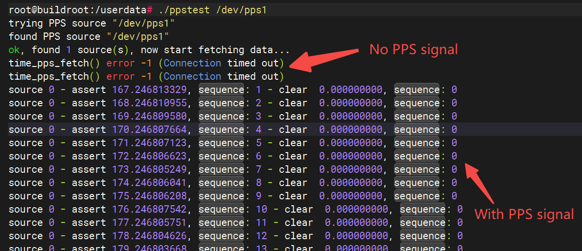
The test tool can directly use open-source code: https://github.com/redlab-i/pps-tools
Compilation instructions are also available in the repository’s README.
4.3.27.6. Common Issues
Q: How to confirm whether the PPS signal is actually generated?
A: An oscilloscope can be used to observe the signal. After connecting to the PPS signal generator, if a waveform like the one below appears, it indicates the PPS signal is being generated correctly.
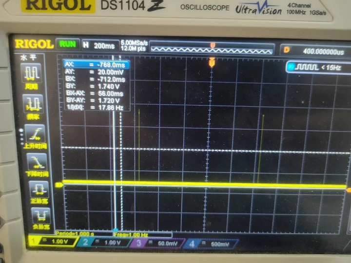
If a PPS device is temporarily unavailable, a PWM signal can also be used to simulate the PPS signal to verify normal PPS testing. The signal in the figure above was generated using PWM simulation.