4.3.19. Audio Development and Debugging Guide
4.3.19.1. Overview
Audio primarily implements digital audio playback and analog audio capture functionalities, which are commonly referred to in consumer terminals as speakers, microphones, headphones, and other audio devices. To achieve these functionalities, the I2S (Inter-IC Sound) bus is often used. I2S, known in Chinese as the Integrated Circuit Built-in Audio Bus, is a bus standard established by Philips Semiconductor (now NXP Semiconductors) for data transmission between digital audio devices.
4.3.19.2. Features
The chip has two full-duplex I2S signal lines, with a maximum rate of 40 Mbps in Master mode.
Supports both master and slave modes
RX supports 1/2/4/8/16 channel audio input
TX supports 1/2 channel audio output
Supports sampling rates of 8/16/32/44.1/48/64 KHz
Supports sampling depths of 16/24/32 bits
TDM (Time-Division Multiplexing) mode requires 32-bit alignment.
4.3.19.3. Functional Description
Typical Applications
There are two typical application scenarios for Audio: playback and capture. In terms of hardware implementation, full-duplex connections use the following connection method. The difference lies in whether control signals are present—one scenario lacks control signals, while the other includes an additional set of control signal lines.
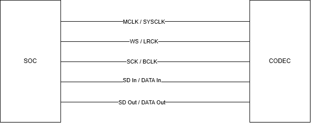
In the figure above, the CODEC connects to the SOC via I2S. When clock signals are correct, playback sends data to the CODEC through the SD Out / DATA OUT line, and capture receives data from the CODEC via SD In / DATA In.
Such CODECs without control signals do exist in the market, but some also include control signal lines. For example, in the following figure, the CODEC and SOC connect via I2C to transmit control signals. Such setups generally involve partial routing control or more complex CODEC drivers.
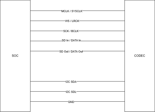
Functional Principles
I2S transmission mainly involves the following types of data lines:
MCLK / SYSCLK: Represents the Master Clock or System Clock, used for synchronization between SOC and CODEC.
SCK / BCLK: Represents the Serial Clock or Bit Clock. SCK is a synchronization signal within the module, provided externally in slave mode and generated internally in master mode. Each pulse corresponds to one bit of digital audio data.
WS / LRCK: Represents the Word Select (sampling clock), also known as the Left-Right Clock (Left Right Clock).
SD / DATA: Represents the Serial Data signal, also called the data line, used primarily for transmitting digital audio data. In full-duplex mode, there are two such lines—one for SOC transmission (commonly used for playback) and one for SOC reception (commonly used for capture).

In Audio development, we frequently encounter the following concepts:
Sampling Rate: The number of times sound samples are taken per second, understood as how many times the ADC/DAC values are updated per second. Common sampling rates include 8/16/32/44.1/48/64 KHz. Its frequency is essentially consistent with that of WS/LRCK. For example, when playing an audio file with a 16 KHz sampling rate, the frequency of the WS / LRCK pin should also be 16 KHz.
Bit Width: Can be understood as the dynamic range of loudness. The larger the bit width, the higher the precision of digital sound, resulting in more refined audio quality. It is also commonly referred to as bit depth. In the figure above, it represents the number of bits in one channel of SD / DATA. For instance, 0-15 indicates 16-bit. Common bit depths include 16-bit and 24-bit.
Number of Channels: Usually understood as the number of connected microphones or speakers. For example, stereo left and right channels constitute two channels.
Clock Relationships: Audio has multiple clocks, so here we separately explain the relationships among them. As mentioned earlier, the sampling rate value is essentially the frequency of WS / LRCK. Based on this, we can derive the frequency of SCK / BCLK using the formula: Bit Width × Number of Channels × Sampling Rate. For example, when playing an audio file with a 16-bit bit depth, dual channels, and a 16 KHz sampling rate, the theoretical frequency of SCK / BCLK should be 16 × 2 × 16 KHz = 512 KHz. If during debugging we find that SCK is not 512 KHz, then we need to debug and check whether there is an anomaly in the clock provided by the Master side. At this point, the frequency of MCLK / SYSCLK may have multiple values, but generally follows this pattern: MCLK is typically 2, 4, or 8 times BCLK, meaning it could be 1.024M, 2.048M, or 4.096M. MCLK is usually 256 times WS, i.e., 256 × 16 KHz = 4.096M. However, this frequency mainly depends on the settings on the CODEC and SOC sides and does not necessarily strictly conform to any one of these values, but must be one of them; otherwise, the output sound will have defects.
Operating Modes
Audio operation involves a series of processes that run through the entire system. We need to ensure that each node functions correctly for the entire Audio system to work properly, similar to a camera’s pipeline.
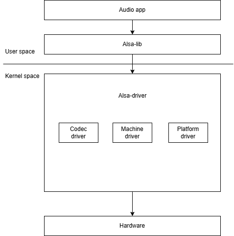
Assuming correct hardware wiring, when the CODEC powers on normally (if there is a control interface, confirm whether it can be controlled properly, e.g., normal I2C communication), and the SOC side settings are correct and successfully integrated into the ALSA framework, ensuring the sound card can start and be used normally.
Then we use Audio tools like tinymix or amixer. Detailed usage instructions can be found in the Function Usage section of this document.
4.3.19.4. Driver Code
There is basically no relevant configuration in U-Boot, so the code and configuration are mainly concentrated in the kernel part. Since the X5 EVB board does not have a Codec chip, we will use the externally connected 40-pin audio board (WM8960) as an example. Other audio boards can be debugged according to actual conditions by referring to the kernel phase in the Function Usage section.
Kernel Driver Code, Configuration, and Device Tree
DTS Part: Additions should be made to the device tree corresponding to the board, for example, the corresponding device tree is x5-evb-lp4-1_b.dts.
&i2c5 {
        wm8960:wm8960@1a{
                compatible = "wlf,wm8960";
                reg = <0x1a>;
                #sound-dai-cells = <0>;
                status = "okay";
        };
};

......

&dw_i2s1 {
        status = "okay";
        dwc-master = <1>; /* dwc-master here indicates the SOC side is master */
};

......

&hobot_sound_machine{

        status = "okay";
        #address-cells = <1>;
        #size-cells = <0>;
        simple-audio-card,name = "duplex-audio-i2s1";

        simple-audio-card,dai-link@0 {
                link-name = "dai-link0";
                reg = <0>;
                format = "i2s";
                bitclock-master = <&snd1_mm>;
                frame-master = <&snd1_mm>;
                snd1_mm: cpu {
                        sound-dai = <&dw_i2s1 1>;
                };
                codec {
                        sound-dai = <&wm8960>;
                };
        };

};
Combining with the ALSA framework, we need to confirm the following code locations.
Codec, i.e., codec-dai code location: kernel/sound/soc/codecs/xxx.c. This part contains numerous codes, including codec codes already uploaded to the Linux mainline.
Platform, i.e., cpu-dai code location: kernel/sound/soc/dwc/dwc-i2s.c. This part follows the platform and is generally not extensive.
Machine code location: kernel/sound/soc/hobot. This part is also SOC-related and mainly connects codec-dai and cpu-dai.
Enable relevant codec config switches, for example, confirm the relevant macro definitions for codec, machine, and platform.
CONFIG_SND_DESIGNWARE_I2S=y
CONFIG_SND_SOC_WM8960=m
CONFIG_SND_HOBOT_SOUND_MACHINE=m
We also recommend enabling required codecs via make menuconfig, following the steps below:
For codecs not on the mainline, add the codec driver file to the kernel/sound/soc/codecs/ directory.
Modify sound/soc/codecs/Kconfig and Makefile to include the codec in driver compilation.
For Kconfig, refer to the following code addition:
config SND_SOC_XXX
    tristate "XXX Audio Codec"
For Makefile, refer to the following code addition:
obj-$(CONFIG_SND_SOC_XXX) += XXX.o
After completing the steps mentioned above, codecs can be enabled via make menuconfig just like those existing on the mainline. The path can be referenced as follows:
-> Device Drivers
    <*> Sound card support --->
        <*> Advanced Linux Sound Architecture --->
            <*> ALSA for SoC audio support --->
                    CODEC drivers --->
                        <M> XXX Audio Codec
4.3.19.5. Function Usage
Kernel Phase Usage
When using Audio, multiple stages need to be connected. We will follow the operating mode mentioned earlier, connecting from bottom to top.
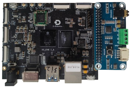
First is the normal registration of the Codec. Again, taking WM8960 as an example (wiring diagram as shown above), ensure that the I2C communication of the Codec is normal. This primarily involves debugging the Codec’s own driver.
For SPI communication, refer to the SPI debugging manual for debugging. Similarly, for I2C communication, refer to the I2C debugging manual.
Here we need to confirm three points: whether power-up is normal, I2C address, and I2C speed.
After configuring according to the device tree and code provided above, after normal startup, manually load the ko module, refer to the following commands:
modprobe designware_i2s i2s_ms=1
modprobe snd-soc-wm8960
modprobe snd-soc-hobot-sound-machine
We can detect the device address on the corresponding I2C bus and even find the device corresponding to that address, locating the file node for printing register values.
# Detect device address

root@buildroot:~# i2cdetect -y -r 5
     0  1  2  3  4  5  6  7  8  9  a  b  c  d  e  f
00:                         -- -- -- -- -- -- -- --
10: -- -- -- -- -- -- -- -- -- -- UU -- -- -- -- --
20: -- -- -- -- -- -- -- -- -- -- -- -- -- -- -- --
30: -- -- -- -- -- -- -- -- -- -- -- -- -- -- -- --
40: -- -- -- -- -- -- -- -- -- -- -- -- -- -- -- --
50: -- -- -- -- -- -- -- -- -- -- -- -- -- -- -- --
60: -- -- -- -- -- -- -- -- -- -- -- -- -- -- -- --
70: -- -- -- -- -- -- -- --
root@buildroot:~#
# Find the node that can print registers

cat /sys/kernel/debug/regmap/5-001aregisters > 0x1a_registers.txt
Next, we can check if codec-dai has registered normally. Under normal circumstances, the codec driver contains functions similar to the following:
snd_soc_register_codec
devm_snd_soc_register_component
Under normal circumstances, there should be no errors. If registration fails, specific error messages will be returned. Generally, the issue lies in the device tree node configuration. Debugging can be done by referring to the code of each codec driver.
Then we need to check the cpu-dai part, which essentially involves registering and checking the I2S controller. The corresponding code and configurations have been mentioned above. Here, we mainly check the part where our I2S works with the CODEC.
Confirm the I2S controller mode, ensuring confirmation on both SOC and codec sides.
Confirm whether there are restrictions on bit width, common bit widths being 16/24/32bit.
Confirm the transmission format, such as left-aligned or right-aligned.
Confirm whether there are restrictions on sampling rate, for example, some CODECs have fixed MCLK, allowing only specific sampling rates.
For instance, our I2S master-slave mode is configured in the DTS. Similarly, if there are registration anomalies, the kernel will print error logs, allowing judgment based on specific situations; however, if debugging during playback or recording, we need to reconfirm the I2S and CODEC cooperation part mentioned earlier. In most cases, improper settings here lead to issues such as silence, stuttering, or abnormal sounds during operation.
Finally, we need to connect codec dai and cpu dai through the machine. This configuration involves DTS and deconfig selection. After completion, we can check in the system whether the sound card has registered successfully and whether there are corresponding PCM devices.
# Check sound cards; X5 EVB has a default dummy sound card

root@buildroot:/proc/asound# cat cards
 0 [guaaudio       ]: gua-audio - gua-audio
                      gua-audio
root@buildroot:/proc/asound#


# After normal registration, two sound cards can be seen
root@buildroot:~# cat /proc/asound/cards
 0 [guaaudio       ]: gua-audio - gua-audio
                      gua-audio
 1 [duplexaudioi2s1]: simple-card - duplex-audio-i2s1
                      duplex-audio-i2s1


## Check PCM devices, information such as id and name can be seen, matching those in the codec.

root@buildroot:~# cat /proc/asound/duplexaudioi2s1/pcm0c/info
card: 1
device: 0
subdevice: 0
stream: CAPTURE
id: i2s1-wm8960-hifi wm8960-hifi-0
name: i2s1-wm8960-hifi wm8960-hifi-0
subname: subdevice #0
class: 0
subclass: 0
subdevices_count: 1
subdevices_avail: 1
root@buildroot:~# cat /proc/asound/duplexaudioi2s1/pcm0p/info
card: 1
device: 0
subdevice: 0
stream: PLAYBACK
id: i2s1-wm8960-hifi wm8960-hifi-0
name: i2s1-wm8960-hifi wm8960-hifi-0
subname: subdevice #0
class: 0
subclass: 0
subdevices_count: 1
subdevices_avail: 1
root@buildroot:~#
A common issue is incorrect machine configuration in the DTS, leading to failed sound card registration. Here we need to clearly confirm the machine configuration.
After completing the above usage configurations, the kernel space part is basically complete, followed by user-space usage.
User-Space Usage
This requires common embedded audio tools like tinyalsa, generally including three basic tools: tinymix for debugging paths, tinycap for recording, and tinyplay for playback.
tinymix explanation:
# tinymix -h
    usage: tinymix [options] <command>
    options:
        -h, --help               : prints this help message and exits
        -v, --version            : prints this version of tinymix and exits
        -D, --card NUMBER        : specifies the card number of the mixer

    commands:
        get NAME|ID              : prints the values of a control
        set NAME|ID VALUE(S) ... : sets the value of a control
        VALUE(S): integers, percents, and relative values
                Integers: 0, 100, -100 ...
                Percents: 0%, 100% ...
                Relative values: 1+, 1-, 1%+, 2%+ ...
        controls                 : lists controls of the mixer
        contents                 : lists controls of the mixer and their contents
Example commands:
View current codec-supported settings (each Codec’s paths generally differ, so this is just an example; operations should be based on actual conditions, such as the following operations on WM8960, which follow the settings in the WM8960 CODEC)
#:/userdata# tinymix contents
Set properties via control:
#:/userdata# tinymix set 6 120
#:/userdata# tinymix get 6
120 (range 0->255)
Set properties via name:
#:~# tinymix set "ADC4 PGA gain" 1
#:~# tinymix get "ADC4 PGA gain"
1 (range 0->31)
tinycap explanation:
#:/userdata# tinycap
Usage: tinycap {file.wav | --} [-D card] [-d device] [-c channels] [-r
rate] [-b bits] [-p period_size] [-n n_periods] [-t time_in_seconds]
Use -- for filename to send raw PCM to stdout
Example command:
tinycap /userdata/test.wav -D 1 -d 0 -t 5
tinyplay explanation:
#:/userdata# tinyplay
usage: tinyplay file.wav [options]
options:
-D | --card <card number> The device to receive the audio
-d | --device <device number> The card to receive the audio
-p | --period-size <size> The size of the PCM's period
-n | --period-count <count> The number of PCM periods
-i | --file-type <file-type > The type of file to read (raw or wav)
-c | --channels <count> The amount of channels per frame
-r | --rate <rate> The amount of frames per second
-b | --bits <bit-count> The number of bits in one sample
-M | --mmap Use memory mapped IO to play audio
Example command:
tinyplay [file.wav] -D 1 -d 1
After determining the tools, we need to confirm the audio routing. We should first read the Audio Codec manual, preferably finding a diagram like this: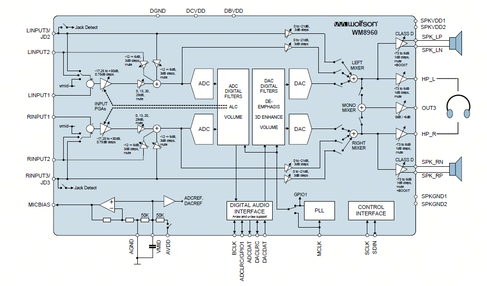
It can vividly illustrate the connection of Audio routing.
Then, use the tinymix command to confirm the routing: Our Device number used is 1, so when operating, -D should be followed by 1
tinymix -D 1 contents
Then we can establish the routing and perform Audio recording and playback.
Recording:
tinymix -D 1 set 'Left Input Boost Mixer LINPUT1 Volume' 3
tinymix -D 1 set 'Right Input Boost Mixer RINPUT1 Volume' 3

tinymix -D 1 set 'Left Input Boost Mixer LINPUT1 Volume' 1
tinymix -D 1 set 'Right Input Boost Mixer RINPUT1 Volume' 1

tinymix -D 1 set 'Capture Volume' 40,40
tinymix -D 1 set 'ADC PCM Capture Volume' 200,200

tinymix -D 1 set 'Left Boost Mixer LINPUT1 Switch' 1
tinymix -D 1 set 'Right Boost Mixer RINPUT1 Switch' 1

tinymix -D 1 set 'Left Input Mixer Boost Switch' 1
tinymix -D 1 set 'Right Input Mixer Boost Switch' 1

tinymix -D 1 set 'Capture Switch' 1,1

tinycap /userdata/2chn_test.wav -D 1 -d 0 -c 2 -b 16 -r 48000 -p 512 -n 4 -t 5
Playback:
tinymix -D  1 set 'Left Output Mixer PCM Playback Switch' 1
tinymix -D  1 set 'Right Output Mixer PCM Playback Switch' 1
tinymix -D  1 set 'Speaker DC Volume' 3
tinymix -D  1 set 'Speaker AC Volume' 3
tinymix -D  1 set 'Speaker Playback Volume' 127 , 127
tinymix -D  1 set 'Playback Volume' 255 , 255
tinymix -D  1 set 'Left Output Mixer PCM Playback Switch' 1
tinymix -D  1 set 'Right Output Mixer PCM Playback Switch' 1

tinyplay /userdata/2chn_test.wav -D 1 -d 0
4.3.19.6. Common Issues
Q1: How to troubleshoot silence issues?
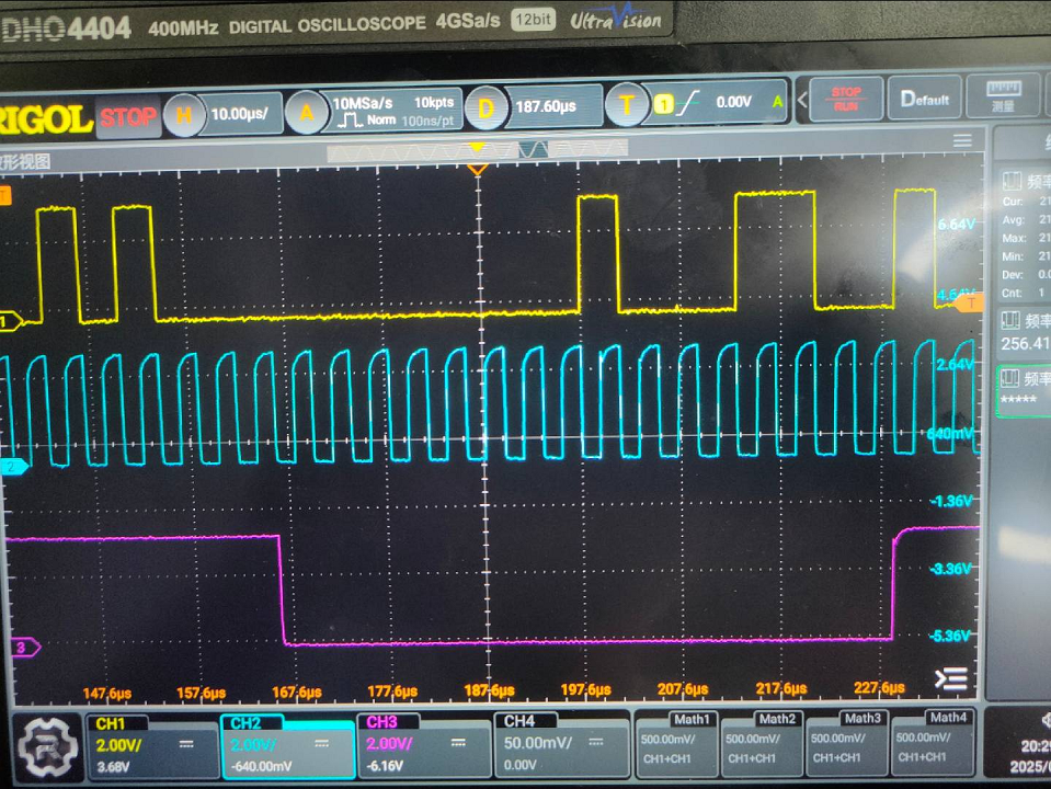
Similarly, using the node-based approach mentioned in the operating mode, investigate each point. First, differentiate the scenario: is it playback silence or recording silence? Then troubleshoot software and hardware; the troubleshooting order generally follows the audio source sequence. For example, for playback, first check if the audio source issued by the software is abnormal, whether the I2S status is correct, whether the codec register status is correct, and finally whether the I2S signal and clock are correct. Of course, if convenient, directly measuring signals when the audio source is confirmed normal can directly identify board status rather than hardware side issues. Recording is the reverse process. For example, in the figure below, we can see that the I2S hardware signal is normal.
Yellow represents the DATA line
Blue represents BCLK
Purple represents LRCLK
Q2: Few LOGs, unable to locate the problem, what to do?
Adjust debug log level
echo "8 4 1 7" > /proc/sys/kernel/printk
echo -n "file dwc-i2s.c +p" > /sys/kernel/debug/dynamic_debug/control
Q3: How to determine sound card registration success and PCM device correspondence?
ALSA has procfs, mounted directory: /proc/asound. ALSA uses files under the /proc/asound directory to save device information and control purposes. Key debugging information is introduced as follows.
/proc/asound/cards: List of registered sound cards. By checking this node, examine the list of registered sound cards in the current system or verify if the sound card has registered successfully.
/proc/asound/pcm: Information about allocated PCM stream devices. By checking this node, find the list of devices supported by the current sound card. This helps in selecting card/device values during testing.
/proc/asound/cardX/pcmY[c, p]/: Each PCM stream device corresponding to a sound card in the system has a similar procfs directory as above. X represents the sound card number, confirmed via /proc/asound/cards or device node information under /dev/snd; Y represents the device number, confirmed via /proc/asound/pcm or device node information under /dev/snd. c/p represent capture/playback respectively. This directory allows viewing PCM device information and status.
info General information about the PCM stream, such as sound card number, device number, stream type, bound codec type, etc.
hw_params When the PCM stream is open, view basic parameter configurations such as sampling rate, bit width, number of channels, period_size, buffer_size, etc. The configured period_size and buffer_size may differ from the printed values here. The actual values should be based on what is viewed here, corresponding to the actual hardware parameters.
#:/proc/asound/card0/pcm0c/sub0# cat hw_params
access: RW_INTERLEAVED
format: S16_LE
subformat: STD
channels: 2
rate: 48000 (48000/1)
period_size: 1024
buffer_size: 4096
sw_params When the PCM stream is open, view start_threshold, stop_threshold, silence_threshold, etc. Focus on start_threshold and stop_threshold thresholds. start_threshold: If this value is set too high, the delay from starting playback to sound output will be too long, causing very brief sounds not to play. stop_threshold: Condition for judging xrun triggering. When available space exceeds this value, xrun will be triggered.
#:/proc/asound/card0/pcm0c/sub0# cat sw_params
tstamp_mode: ENABLE
period_step: 1
avail_min: 1
start_threshold: 1
stop_threshold: 40960
silence_threshold: 0
silence_size: 0
boundary: 4611686018427387904
status View the current substream status (running, xrun, etc.), and the values of appl_ptr/hw_ptr pointers. Among these, hw_ptr and appl_ptr can identify situations where the underlying hardware cannot transmit or receive any data. For example, testing starts but interrupts are not properly triggered, data transmission will stall. At this time, the hw_ptr/appl_ptr pointers will not update continuously.
Q4: What is an xrun issue, and how to locate and resolve it when encountered?
Intermittent or continuous audio playback with interruptions, sounds like “hissing” or “popping” noise, usually indicates an xrun has occurred. Xrun frame loss is unavoidable due to system performance limitations. Under usage scenario requirements, some frame loss rate is allowed, and optimization methods can be used to minimize it as much as possible. If xrun occurs frequently and cannot recover, code implementation defects need to be investigated.
Scenarios where xrun may occur
During playback, the application continuously fills audio data into the driver buffer, which is sent via I2S to the codec for playback. When the application fills too slowly, causing the driver buffer to empty, underrun is triggered, leading to frame loss and possible audio anomalies.
During recording, the digital signal converted by the codec is filled into the driver buffer via I2S, and the application reads audio data from the driver buffer. When the application read speed cannot keep up with the write speed, exceeding the stop_threshold will trigger overrun.
Usage scenarios triggering xrun anomalies
Audio data comes from storage, IO operations take time
Accessing RAM disk and reading/writing PCM devices running single-threaded
Low priority of voice processes, higher priority tasks preempting
Locating xrun
Xrun issues are quite diverse, so we should collect and organize problems as much as possible to provide richer references.
Check if xrun is caused by time-consuming IO operations
Write audio files to RAM disk or specific device files, refer to commands
mkdir /data/audio_test
tinycap /data/audio_test/test.wav

tinycap /dev/null
Note: The above can only be used to determine if xrun is caused by time-consuming IO operations, not as a solution to xrun.
Optimize application testing
Use separate threads to access media storage and read/write PCM devices.
Taking recording as an example, create a separate thread for writing files and create a ring buffer (ring buffer size can be freely adjusted), write pcm_read buffer into the ring buffer, and fread reads data from the ring buffer. As long as fwrite falls into the limit of ring buffer, xrun will not occur.
Obtain information by configuring certain features under /proc
Enable the xrun_debug config option during compilation. Compile and re-flash the image. (If xrun_debug already exists, the feature is already enabled—this step is not needed.)
CONFIG_SND_PCM_XRUN_DEBUG=y
CONFIG_SND_VERBOSE_PROCFS=y
CONFIG_SND_DEBUG=y
Corresponding path: /proc/asound/cardX/pcmY[c,p]/xrun_debug
For example, writing 3 into xrun_debug enables basic debugging and stack dump functionality, which helps check whether the PCM stream has stopped due to some reason.
# Enable basic debugging and dump stack
# Useful to just see, if PCM stream is stopped for a reason (usually wrong audio process timing from scheduler)
echo 3 > /proc/asound/card0/pcm0p/xrun_debug
Analyze issues using ftrace
Ftrace is a kernel debugging and performance analysis tool used to investigate potential causes of xrun. Check whether long interrupt durations are causing delayed scheduling.
Enable ftrace-related config options during compilation. Compile and re-flash the image.
CONFIG_FTRACE=y
CONFIG_FUNCTION_TRACER=y
CONFIG_FUNCTION_GRAPH_TRACER=y
CONFIG_STACK_TRACER=y
CONFIG_DYNAMIC_FTRACE=y
Generate trace file
echo > /sys/kernel/debug/tracing/trace
echo 1 > /sys/kernel/debug/tracing/events/signal/enable
app_test  # Run your application
killed
echo 0 > /sys/kernel/debug/tracing/events/signal/enable
cat /sys/kernel/debug/tracing/trace > /userdata/trace.txt
Alternatively, use the trace-cmd tool. Here is the detailed script:
#!/bin/sh
date
rm /userdata/trace.dat
echo "" > /userdata/log/usr/message
trace-cmd record -e irq -e sched_switch -e sched_wakeup -o /userdata/trace.dat &
cnt=0
while true;do
    nr=$(grep -r "audio unexpected delay count" /userdata/log/usr/message | wc -l)
    echo "nr " $nr
    if [ $nr -gt 1 ];then
    echo "find the error message, send the SIGINT Term Interrupt to the trace-cmd !"
    kill -2 $(pidof trace-cmd)
    date
    exit 0
    else
    if [ $cnt -gt 100 ];then
        date
        cnt=0
        echo "rm the trace.dat file, and restart the trace-cmd"
        kill -9 $(pidof trace-cmd)
        rm -rf /userdata/trace.dat
        trace-cmd record -e irq -e sched_switch -e sched_wakeup -o /userdata/trace.dat &
    fi
    fi
    cnt=$((cnt+1))
    sleep 1
done
Analyze the trace file
There are multiple ways to analyze the trace file, such as using Google Trace Viewer or Kernelshark.
If using Google Trace Viewer, the source code must be modified to revert to lazy-compatible trace output, ensuring the output trace file meets Google Trace Viewer’s format requirements. Patch as follows:
diff --git a/kernel/trace/Kconfig b/kernel/trace/Kconfig
index 29db703f6880..86de03221287 100644
--- a/kernel/trace/Kconfig
+++ b/kernel/trace/Kconfig
@@ -870,6 +870,10 @@ config HIST_TRIGGERS_DEBUG

       If unsure, say N.

+config OLD_TRACE
+   bool "old ftrace"
+   default y
+
 endif # FTRACE

 endif # TRACING_SUPPORT
diff --git a/kernel/trace/trace_output.c b/kernel/trace/trace_output.c
index bc24ae8e3613..e0df7a412c95 100644
--- a/kernel/trace/trace_output.c
+++ b/kernel/trace/trace_output.c
@@ -482,16 +482,23 @@ int trace_print_lat_fmt(struct trace_seq *s, struct trace_entry *entry)
    hardirq              ? 'h' :
    softirq              ? 's' :
                   '.' ;
-
+#ifndef CONFIG_OLD_TRACE
    trace_seq_printf(s, "%c%c%c%c",
         irqs_off, need_resched, need_resched_lazy,
         hardsoft_irq);
-
+#else
+   trace_seq_printf(s, "%c%c%c",
+            irqs_off, need_resched,
+            hardsoft_irq);
+#endif
    if (entry->preempt_count)
    trace_seq_printf(s, "%x", entry->preempt_count);
    else
    trace_seq_putc(s, '.');

+
+
+#ifndef CONFIG_OLD_TRACE
    if (entry->preempt_lazy_count)
    trace_seq_printf(s, "%x", entry->preempt_lazy_count);
    else
@@ -501,7 +508,7 @@ int trace_print_lat_fmt(struct trace_seq *s, struct trace_entry *entry)
    trace_seq_printf(s, "%x", entry->migrate_disable);
    else
    trace_seq_putc(s, '.');
-
+#endif
    return !trace_seq_has_overflowed(s);
 }
For more information about ftrace generation and usage, please refer to the official documentation:
https://www.kernel.org/doc/html/latest/trace/ftrace.html
https://perfetto.dev/docs/data-sources/cpu-scheduling
https://git.kernel.org/pub/scm/linux/kernel/git/rostedt/trace-cmd.git/
https://kernelshark.org/Documentation.html#graph-info-line
In general, there are several directions to troubleshoot xrun issues:
Increase thread priority (use real-time thread + priority value)
Increase
period_sizeto change DMA transfer data volumeImplement asynchronous I/O and ALSA device read/write