PHY Driver Debug Guide
Preface
PHY (Port Physical Layer) is a common abbreviation for the physical layer of the OSI model. Ethernet PHY chips, in the typical sense, are used to connect Ethernet MAC devices (such as SoCs integrating EMAC controllers, e.g., Horizon Journey or Sunrise series chips) with specific transmission media. This document uses the Marvell 88E1512 PHY as an example to illustrate the process of adapting the PHY for the Horizon X3 GMAC network interface.
Ethernet-PHY Capabilities and Constraints of Horizon Chips
Overview of Horizon Ethernet-PHY Interface Capabilities
Supports full-duplex and half-duplex modes.
Supports 100 Mbps and 1000 Mbps; does not support 10 Mbps.
Supports RGMII and RMII types of MII data interfaces; does not support other interface types.
Supports MDIO interface: X3/J3/J5 support Clause 22; J5 supports Clause 45. The MDIO interface clock is adjustable (default 2 MHz; per IEEE 802.3, the recommended clock range is between 1 MHz and 2.5 MHz. Adjustments are not recommended unless specifically required).
Supports 1.8V power domain; does not support 3.3V or other power domains.
Can output a 25 MHz EPHY_CLK as a reference clock for external PHYs.
Does not support clock delay; the PHY or switch must support this feature and have it enabled.
Does not support additional reset pins; if needed, other GPIO pins may be reused based on board design.
Does not support PHY interrupt mode; only supports polling to read PHY status.
Circuit Design Checklist (System Software Related)
MII interface (rgmii/rmii/mdio) voltage levels only support 1.8V power domain.
If the PHY reset pin is driven by a GPIO, ensure that the selected pin, reset logic, and reset timing match the DTS description.
If the PHY reset pin connects to an RC circuit or other reset circuitry, ensure the chip is in a reset-complete state before being accessed.
The Horizon chip does not support adjusting clock delay, so the PHY must either enable this function by default or provide driver support to enable it.
PHY Adaptation in U-Boot
Build Configuration
In U-Boot, the GMAC driver reads the values of registers 0x2 and 0x3 via the MDIO bus—these represent the PHY ID. For the Marvell 88E1512, register 0x2 has the value 0x0141 and register 0x3 has 0x0dd0. Therefore, the PHY ID for 88E1512 is 0x01410dd0. When the Marvell PHY build option is enabled in the U-Boot configuration file, the Marvell 88E1512 PHY driver registers this ID during probe, allowing the X3 GMAC driver to recognize the 88E1512 based on the detected PHY ID.
Enable Marvell PHY build option:
# uboot/configs/xj3_soc_defconfig
CONFIG_PHY_MARVELL=y
DTS Configuration
In a new project DTS, directly include the gmac node defined in hobot-xj3.dtsi, then add corresponding properties. For example:
new_project.dts:
#include "hobot-xj3.dtsi"
......
&gmac {
        status = "okay";
        phyaddr = <0xe>;          // PHY address, current address is 0xe
        phy-mode = "rgmii-id";    // PHY mode; use "rmii-id" for RMII
};
......
X3/J3 only support adding two properties: phyaddr and phy-mode.
It does not support specifying a reset GPIO in DTS.
It does not support fixed mode (connected to a switch).phy-mode only supports "rmii-id" and "rgmii-id"; other modes are unsupported.
Since X3 GMAC does not support configuring Timing Delay on TX and RX of the RGMII interface, TX and RX Timing Delay must be enabled in the PHY configuration. Generally, setting phy-mode to "rgmii-id" in DTS achieves this.
static const char * const phy_interface_strings[] = {
		...
        [PHY_INTERFACE_MODE_RMII]               = "rmii",
        [PHY_INTERFACE_MODE_RGMII]              = "rgmii",
        [PHY_INTERFACE_MODE_RGMII_ID]           = "rgmii-id", # rx and tx delay
        [PHY_INTERFACE_MODE_RGMII_RXID]         = "rgmii-rxid", # rx delay
        [PHY_INTERFACE_MODE_RGMII_TXID]         = "rgmii-txid", # tx delay
		...
};
If the customer uses a different PHY address than the Horizon reference hardware (which uses 0xe), the phyaddr value must be updated in the DTS.
PIN Drive Capability Configuration
If signal electrical characteristics or timing do not meet requirements under default settings, adjust pull-up/down and drive strength of relevant pins based on actual waveform observations.
Under X3/J3 U-Boot, PIN drive capability cannot be configured via DTS. Instead, low-level register settings must be modified directly. Relevant registers are from 0xA600_4098 to 0xA600_40D0. It is recommended to place register modifications at the entry of eqos_probe. Refer to the document:《RM-2501-5-J3 Register Reference Manual-GPIO&PIN-V1.1.pdf》for specific register details.
EMAC Driver Source Code Adaptation Method
If using a standard PHY chip with circuit design referencing DVB, CVB, SDB, etc., no modification is typically needed.
If the PHY reset pin differs from the reference design, it is recommended to implement reset logic at the entry of
eqos_probe.
For example, if the board uses BIFSD_DATA2 as the reset pin, where the PHY chip resets on low level, requires at least 10ms reset duration, and becomes accessible 20ms after reset, follow these steps:
According to the reference document 《PL-2501-3-J3 PIN SW Reg-V1.1.xls》, BIFSD_DATA2 corresponds to GPIO[24] (i.e., GPIO1.8, see worksheet PIN Mux List), and its PIN function configuration register is
0xA600_4060.
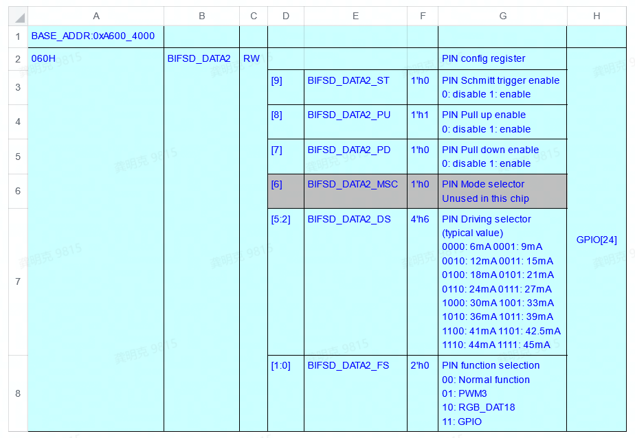
According to 《RM-2501-5-J3 Register Reference Manual-GPIO&PIN-V1.1.pdf》, GPIO group 1 direction and output value configuration register is
0x6000_3018. The upper 16 bits configure direction (bit0 for gpio0, bit1 for gpio1, etc.), and lower 16 bits configure output value.
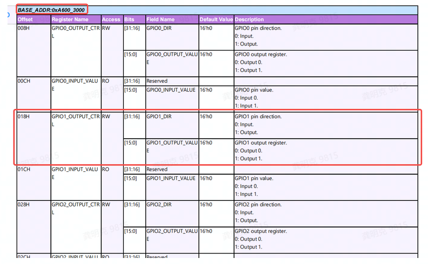
Based on PHY chip requirements, design reset logic as follows:
static int eqos_probe(struct udevice *dev)
{
    unsigned int reg_val;
    ......
    // Set PIN function to GPIO
    reg_val = readl(0xA6004060);
    reg_val |= 0x3;
    writel(reg_val, 0xA6004060);
    ......
    // Set GPIO1.8 direction to output
    reg_val = readl(0xA6003018);
    reg_val |= 0x01000000;
    writel(reg_val, 0xA6003018);
    ......

    // Reset logic
    reg_val = readl(0xA6003018);
    reg_val &= ~0x00000100;    // Pull GPIO1.8 low
    mdelay(10);               // Hold low for 10ms

    reg_val = readl(0xA6003018);
    reg_val |= 0x00000100;    // Pull GPIO1.8 high
    mdelay(20);
    ......
    // PHY registers can now be accessed normally
}
If other pins are used, follow the same steps accordingly.
If the PHY chip’s auto-negotiation time is long (over 4 seconds), modify the macro
PHY_ANEG_TIMEOUT(uboot/include/phy.h) to extend the timeout.Regardless of whether the NIC is used in U-Boot, correct DTS configuration must be made.
Test Method
To test network connectivity in U-Boot, connect the X3 Ethernet port directly to a PC’s Ethernet port and set the PC NIC to a fixed IP address, for example:
IP Address: 192.168.1.195
Subnet Mask: 255.255.255.0
Gateway: 192.168.1.1
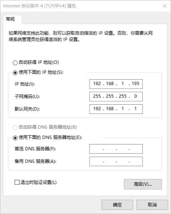
Then connect to the development board via serial console, press any key during boot to enter U-Boot command line, and execute:
Hobot>setenv ipaddr 192.168.1.10
Hobot>ping 192.168.1.195
If “host 192.168.1.195 is alive” appears, the network is functioning.
Common Issues
EQOS_DMA_MODE_SWR stuck
If “EQOS_DMA_MODE_SWR stuck” is printed, it indicates GMAC soft reset failed, usually because the GMAC failed to detect PHY RX CLK input. This could be due to improper PHY reset or abnormal clock input causing invalid PHY RX CLK output.
PHY Adaptation in Kernel
Build Configuration
In the kernel, the corresponding PHY build option must also be enabled to compile the PHY driver into the kernel:
CONFIG_MARVELL_PHY=y

DTS Configuration
In a new project DTS, include the gmac node defined in hobot-xj3.dtsi, then add required properties, for example:
new_project.dts:
#include "hobot-xj3.dtsi"
......
ðernet {
status = "okay";
phy-handle = <&phy1>;
phy-mode = "rgmii-id"; // Use "rmii-id" for RMII
mdio {
#address-cells = <0x1>;
#size-cells = <0x0>;
#ifndef FIXED_PHY
// PHY device
/* EPHY_CLK(gpio2.6) is in gpio mode and used as RESET for PHY */
// Reset active low; use "GPIO_ACTIVE_HIGH" if active high
// Omit if PHY does not use GPIO reset
reset-gpios = <&gpios 38 GPIO_ACTIVE_LOW>;
/* reset pin must assert at least extra delay 50ms for MARVELL 88EA1512 */
reset-delay-us = <20000>;
/*
Note: reset_extra_us specifies extra delay after reset, in microseconds.
This is a custom property, not supported in older versions. Apply patch if needed:
*/
reset_extra_us = <60000>;
phy1: phy@e {
//"ethernet-phy-ieee802.3-c22" is required; C45 not supported on X3/J3
compatible = "marvell,88E1111","ethernet-phy-ieee802.3-c22";
reg = <0xe>; // Current PHY address 0xe, must match phy@e
};
#endif
};
#ifdef FIXED_PHY
// Switch device
// If connecting to a switch, add the following node:
// Example: id=1 (must be unique), full duplex, 1000M, no Pause or Asym Pause
// Reference: kernel/Documentation/devicetree/bindings/net/ethernet-controller.yaml
fixed-link = <1 1 1000 0 0>;
#endif
};
If the current X3/J3 version does not support the “reset_extra_us” property but it is required, refer to the following patch:
0001-ethernet-phy-fix-XJ3-4013-Fixed-ETH-PHY-initializati.patch
Pinctrl-DTS Adaptation Method
To adjust drive strength, pull-up/down, etc., of Ethernet-related pins, modify kernel/arch/arm64/boot/dts/hobot/hobot-pinctrl-xj3.dtsi as needed:
pinctrl: pinctrl@0xA6004000 {
    ......
    eth_func: eth_func {
        pinctrl-single,pins = <
            0x098   (MUX_F3 | DRIVE1_06MA | SCHMITT1_DIS | PULL1_DOWN)
            0x09c   (MUX_F0 | DRIVE1_03MA | SCHMITT1_DIS | PULL1_UP)
            0x0a0   (MUX_F0 | DRIVE1_03MA | SCHMITT1_DIS | PULL1_UP)
            0x0a4   (MUX_F0 | DRIVE1_03MA | SCHMITT1_ENA | PULL1_DOWN)
            0x0a8   (MUX_F0 | DRIVE1_03MA | SCHMITT1_DIS | PULL1_UP)
            0x0ac   (MUX_F0 | DRIVE1_03MA | SCHMITT1_DIS | PULL1_UP)
            0x0b0   (MUX_F0 | DRIVE1_03MA | SCHMITT1_DIS | PULL1_UP)
            0x0b4   (MUX_F0 | DRIVE1_03MA | SCHMITT1_DIS | PULL1_UP)
            0x0b8   (MUX_F0 | DRIVE1_03MA | SCHMITT1_DIS | PULL1_DOWN)
            0x0bc   (MUX_F0 | DRIVE1_12MA | SCHMITT1_DIS | PULL1_DIS)
            0x0c0   (MUX_F0 | DRIVE1_12MA | SCHMITT1_DIS | PULL1_DIS)
            0x0c4   (MUX_F0 | DRIVE1_12MA | SCHMITT1_DIS | PULL1_DIS)
            0x0c8   (MUX_F0 | DRIVE1_12MA | SCHMITT1_DIS | PULL1_DIS)
            0x0cc   (MUX_F0 | DRIVE1_12MA | SCHMITT1_DIS | PULL1_DIS)
            0x0d0   (MUX_F0 | DRIVE1_12MA | SCHMITT1_DIS | PULL1_DIS)
        >;
        };
    ......
}
The above example configures the following pins: EPHY_CLK/MDCK/MDIO/RGMII_RX_CLK/RGMII_RXD0/RGMII_RXD1/RGMII_RXD2/RGMII_RXD3/RGMII_RX_DV/RGMII_TX_CLK/RGMII_TXD0/RGMII_TXD1/RGMII_TXD2/RGMII_TXD3/RGMII_TX_EN
DRIVE1_XXMA sets drive strength, with options:
DRIVE1_03MA/06MA/09MA/12MA/17MA/20MA/22MA/25MA/33MA/35MA/37MA/39MA/41MA/42.5MA/44MA/45MA
EMAC Driver Adaptation Method
MDIO Rate Adjustment (not recommended unless necessary)
Part of the MDIO bus rate adjustment code for X3/J3 chips is located in the xj3_mdio_set_csr function. The core logic calculates the divider based on the current clock tree and stores the final value in priv->csr_val. Divider calculation:
priv->csr_val = 0 , MDIO clock frequency = reference clock / 42
priv->csr_val = 1 , MDIO clock frequency = reference clock / 62
priv->csr_val = 2 , MDIO clock frequency = reference clock / 16
priv->csr_val = 3 , MDIO clock frequency = reference clock / 26
priv->csr_val = 4 , MDIO clock frequency = reference clock / 102
priv->csr_val = 5 , MDIO clock frequency = reference clock / 124
priv->csr_val = 6 , MDIO clock frequency = reference clock / 204
priv->csr_val = 7 , MDIO clock frequency = reference clock / 324
Current reference clock is 250 MHz, csr_val is set to 5, so MDIO clock = 250 MHz / 124 ≈ 2 MHz. To change, modify priv->csr_val accordingly.
RMII-PHY Adaptation
The kernel RMII driver lacks configuration for bit 0 and bit 8 of register
0xA1000384. Currently, this is configured in U-Boot, which requires correct DTS setup in U-Boot. If this cannot be guaranteed, set register0xA1000384at a later stage in the MAC driver’s probe function.For RMII-PHY at 100M mode, modify the target clock in
xj3_set_speed. Example modification:
diff --git a/drivers/net/ethernet/hobot/hobot_eth.c b/drivers/net/ethernet/hobot/hobot_eth.c
--- a/drivers/net/ethernet/hobot/hobot_eth.c
+++ b/drivers/net/ethernet/hobot/hobot_eth.c
@@ -1175,11 +1175,11 @@ static void xj3_set_speed(struct xj3_priv *priv) {
         rate_L2 = clk_round_rate(priv->plat->xj3_mac_div_clk, target);
         clk_set_rate(priv->plat->xj3_mac_div_clk, rate_L2);
     } else if (phydev->speed == SPEED_100) {
-        target = 125000000;
+        target = 150000000;
         rate_L1 = clk_round_rate(priv->plat->xj3_mac_pre_div_clk, target);
         clk_set_rate(priv->plat->xj3_mac_pre_div_clk, rate_L1);

-        target = 25000000;
+        target = 50000000;
         rate_L2 = clk_round_rate(priv->plat->xj3_mac_div_clk, target);
         clk_set_rate(priv->plat->xj3_mac_div_clk, rate_L2);
Test Method
Similarly, connect the X3 Ethernet port directly to a PC’s Ethernet port.
Set PC NIC to fixed IP:
IP Address: 192.168.1.195
Subnet Mask: 255.255.255.0
Gateway: 192.168.1.1
Then enter the X3 kernel shell and set its IP:
ifconfig eth0 192.168.1.10 netmask 255.255.255.0
route add default gw 192.168.1.1
Then ping to test connectivity:
ping 192.168.1.195

PING 192.168.1.195 (192.168.1.195) 56(84) bytes of data.
64 bytes from 192.168.1.195: icmp_seq=1 ttl=128 time=0.801 ms
Introduction to Common Tools
Tools in U-Boot
mii: Used primarily for reading/writing PHY registers.
mii - MII utility commands

Usage:
mii device                            - list available devices
mii device <devname>                  - set current device
mii info   <addr>                     - display MII PHY info
mii read   <addr> <reg>               - read  MII PHY <addr> register <reg>
mii write  <addr> <reg> <data>        - write MII PHY <addr> register <reg>
mii modify <addr> <reg> <data> <mask> - modify MII PHY <addr> register <reg>
                                        updating bits identified in <mask>
mii dump   <addr> <reg>               - pretty-print <addr> <reg> (0-5 only)
Addr and/or reg may be ranges, e.g. 2-7.
Example:
// Read register
Hobot>mii read 0xe 2
0141
// Read and parse register
Hobot>mii dump 0xe 0
0.     (1140)                 -- PHY control register --
  (8000:0000) 0.15    =     0    reset
  (4000:0000) 0.14    =     0    loopback
  (2040:0040) 0. 6,13 =   b10    speed selection = 1000 Mbps
  (1000:1000) 0.12    =     1    A/N enable
  (0800:0000) 0.11    =     0    power-down
  (0400:0000) 0.10    =     0    isolate
  (0200:0000) 0. 9    =     0    restart A/N
  (0100:0100) 0. 8    =     1    duplex = full
  (0080:0000) 0. 7    =     0    collision test enable
  (003f:0000) 0. 5- 0 =     0    (reserved)
// View current MII device list
Hobot# mii device
MII devices: 'ethernet@59110000' 'ethernet@59120000'
Current device: 'ethernet@59110000'
// Switch current MII device
Hobot# mii device ethernet@59120000
Hobot# mii device
MII devices: 'ethernet@59110000' 'ethernet@59120000'
Current device: 'ethernet@59120000'
md: Used for reading memory/IO registers.
md - memory display

Usage:
md [.b, .w, .l, .q] address [# of objects]
Example:

Hobot>md 0xA1000000
a1000000: 01102064 00001010 00000001 00000000    d ..............
a1000010: 0120107d 00001010 00000001 00000000    }. .............
a1000020: 0130107d 00001010 00000001 00000000    }.0.............
a1000030: 01101042 00003000 00000001 00a80000    B....0..........
a1000040: 01101044 00001010 00000001 00000000    D...............
......
mw: Used for writing memory/IO registers
mw - memory write (fill)

Usage:
mw [.b, .w, .l, .q] address value [count]

Example:
Hobot>mw 0x20000000 0x1
Hobot>md 0x20000000
20000000: 00000001 ffffffff ffffffff ffffffff    ................
20000010: ffffffff ffffffff ffffffff ffffffff    ................
......
ping: Used to test network connectivity.
ping - send ICMP ECHO_REQUEST to network host

Usage:
ping pingAddress

Hobot>setenv ipaddr 192.168.1.10        // Must set local IP first, same subnet
Hobot>ping 192.168.1.200
Phy name:Marvell 88E1518
Phy uid:1410dd0
ethernet@A5014000 Waiting for PHY auto negotiation to complete....... done
set mac_div_clk = 125000000Using ethernet@A5014000 device
host 192.168.1.200 is alive            // Network is reachable
Tools in Kernel
ethtool: Tool for viewing/modifying network status.
View current link status
root@x3dvbx3-samsung1G-3200:~# ethtool eth0
Settings for eth0:
        Supported ports: [ TP MII ]
        Supported link modes:   10baseT/Full        // NIC supported capabilities
                                100baseT/Full
                                1000baseT/Full
        Supported pause frame use: Symmetric Receive-only
        Supports auto-negotiation: Yes
        Supported FEC modes: Not reported
        Advertised link modes:  10baseT/Full        // Advertised capabilities
                                100baseT/Full
                                1000baseT/Full
        Advertised pause frame use: No
        Advertised auto-negotiation: Yes            // Auto-negotiation enabled
        Advertised FEC modes: Not reported
        Link partner advertised link modes:  10baseT/Half 10baseT/Full  // Link partner capabilities
                                             100baseT/Half 100baseT/Full
                                             1000baseT/Full
        Link partner advertised pause frame use: Symmetric Receive-only
        Link partner advertised auto-negotiation: Yes
        Link partner advertised FEC modes: Not reported
        Speed: 1000Mb/s    // Negotiated speed, duplex, port type
        Duplex: Full
        Port: MII
        PHYAD: 14            // PHY address is 14
        Transceiver: internal
        Auto-negotiation: on
        Link detected: yes

// Modify NIC capabilities, e.g., set to fixed 100M full-duplex
ethtool -s eth0 autoneg off speed 100 duplex full

Check updated status:
root@x3dvbx3-samsung1G-3200:~# ethtool eth0
Settings for eth0:
        Supported ports: [ TP MII ]
        Supported link modes:   10baseT/Full        // NIC supported capabilities
                                100baseT/Full
                                1000baseT/Full
        Supported pause frame use: Symmetric Receive-only
        Supports auto-negotiation: Yes
        Supported FEC modes: Not reported
        Advertised link modes:  100baseT/Full        // Only advertise 100M
        Advertised pause frame use: No
        Advertised auto-negotiation: No              // Auto-negotiation disabled
        Advertised FEC modes: Not reported
        Speed: 100Mb/s        // Link status: 100M full-duplex
        Duplex: Full
        Port: MII
        PHYAD: 14            // PHY address is 14
        Transceiver: internal
        Auto-negotiation: off
        Link detected: yes
phytool: PHY register read/write tool (not supported on older X3/J3 versions; supported on J5)
Usage: phytool read  IFACE/ADDR/REG
       phytool write IFACE/ADDR/REG <0-0xffff>
       phytool print IFACE/ADDR[/REG]
where

ADDR := C22 | C45
C22  := <0-0x1f>
C45  := <0-0x1f>:<0-0x1f>
REG  := <0-0x1f>

Examples:
       phytool read  eth0/0:3/1
       phytool write eth0/0xa/0 0x1140
       phytool print eth0/0x1c
For older X3/J3 versions, apply the following patch to support phytool, or use the gmac_rw_phy.sh script introduced below for PHY access.
0001-eth-phy-feat-XJ3-4413-Add-code-supported-by-the-phyt.patch
gmac_rw_phy.sh (X3/J3 only): Script provided for reading/writing PHY registers. Note: Since the kernel continuously accesses the PHY, it is recommended to perform multiple operations to confirm successful access.
gmac_rw_phy.sh is a register read/write script provided for X3/J3 chips. Usage:
# Common command
# Read 32 registers starting from reg=0 of Phy=0xe (address)
# ./gmac_rw_phy.sh 0xe read_phy  0 32
```#
# Write Phy=0xe (address), reg=1, val=0xc83d
# ./gmac_rw_phy.sh 0xe write_phy  1 0xc83d
For example:
root@x3dvbx3-samsung1G-3200:/userdata# ./gmac_rw_phy.sh 0xe read_phy 0 32
0x2100 0x2100 0x0141 0x0dd4 0x0141 0x0000 0x0004 0x2001
0x0000 0x0200 0x0000 0x0000 0x0000 0x0003 0x0000 0x3000
0x3070 0x6c08 0x0000 0x6400 0x0020 0x0000 0x0000 0x0000
0x0000 0x0000 0x0040 0x0000 0x0000 0x0000 0x0000 0x0000
tcpdump/wireshark: Wireshark is a Windows version packet capture tool with powerful features and easy usage, which will not be described in detail here. Tcpdump is a tool for Linux environments. The D-Robotics chip supports a simplified version of this tool (some very old versions do not, see attached file for download). Although tcpdump is powerful, for PHY-related functions, only some basic options are needed, for example:
root@x3dvbx3-samsung1G-3200:~# tcpdump -h
tcpdump version 4.9.2
libpcap version 1.9.1 (with TPACKET_V3)
OpenSSL 1.1.1g  21 Apr 2020
Usage: tcpdump [-aAbdDefhHIJKlLnNOpqStuUvxX#] [ -B size ] [ -c count ]
                [ -C file_size ] [ -E algo:secret ] [ -F file ] [ -G seconds ]
                [ -i interface ] [ -j tstamptype ] [ -M secret ] [ --number ]
                [ -Q in|out|inout ]
                [ -r file ] [ -s snaplen ] [ --time-stamp-precision precision ]
                [ --immediate-mode ] [ -T type ] [ --version ] [ -V file ]
                [ -w file ] [ -W filecount ] [ -y datalinktype ] [ -z postrotate-command ]
                [ -Z user ] [ expression ]

// Capture packets on the eth0 interface
root@x3dvbx3-samsung1G-3200:~# tcpdump -i eth0
tcpdump: verbose output suppressed, use -v or -vv for full protocol decode
listening on eth0, link-type EN10MB (Ethernet), capture size 262144 bytes
08:04:33.567718 IP 192.168.1.10.ssh > 192.168.1.200.51017: Flags [P.], seq 2043263027:2043263219, ack 955812216, win 315, length 192
08:04:33.572145 IP 192.168.1.10.ssh > 192.168.1.200.51017: Flags [P.], seq 192:416, ack 1, win 315, length 224
08:04:33.572376 IP 192.168.1.10.ssh > 192.168.1.200.51017: Flags [P.], seq 416:496, ack 1, win 315, length 80
......

// Capture packets on the eth0 interface and save them to the file t1.pcap (*.pcap files can be directly opened in Wireshark)
root@x3dvbx3-samsung1G-3200:~# tcpdump -i eth0 -w /userdata/t1.pcap
tcpdump: listening on eth0, link-type EN10MB (Ethernet), capture size 262144 bytes
ifconfig: ifconfig is a Linux tool used to display or configure network devices. Although ifconfig is quite powerful, in PHY-related network applications, usually only the most basic options are needed, for example:
root@x3dvbx3-samsung1G-3200:/# ifconfig -h
Usage:
  ifconfig [-a] [-v] [-s] <interface> [[<AF>] <address>]
  [add <address>[/<prefixlen>]]
  [del <address>[/<prefixlen>]]
  [[-]broadcast [<address>]]  [[-]pointopoint [<address>]]
  [netmask <address>]  [dstaddr <address>]  [tunnel <address>]
  [outfill <NN>] [keepalive <NN>]
  [hw <HW> <address>]  [metric <NN>]  [mtu <NN>]
  [[-]trailers]  [[-]arp]  [[-]allmulti]
  [multicast]  [[-]promisc]
  [mem_start <NN>]  [io_addr <NN>]  [irq <NN>]  [media <type>]
  [txqueuelen <NN>]
  [[-]dynamic]
  [up|down] ...

  <HW>=Hardware Type.
  List of possible hardware types:
    loop (Local Loopback) slip (Serial Line IP) cslip (VJ Serial Line IP)
    slip6 (6-bit Serial Line IP) cslip6 (VJ 6-bit Serial Line IP) adaptive (Adaptive Serial Line IP)
    ether (Ethernet) netrom (AMPR NET/ROM) tunnel (IPIP Tunnel)
    ppp (Point-to-Point Protocol) arcnet (ARCnet) dlci (Frame Relay DLCI)
    frad (Frame Relay Access Device) irda (IrLAP)
  <AF>=Address family. Default: inet
  List of possible address families:
    unix (UNIX Domain) inet (DARPA Internet) inet6 (IPv6)
    netrom (AMPR NET/ROM)

// View network interface status
root@x3dvbx3-samsung1G-3200:/# ifconfig eth0
eth0      Link encap:Ethernet  HWaddr 00:61:7d:31:9f:b9
          inet addr:192.168.1.10  Bcast:192.168.1.255  Mask:255.255.255.0
          inet6 addr: fe80::261:7dff:fe31:9fb9/64 Scope:Link
          UP BROADCAST RUNNING MULTICAST  MTU:1500  Metric:1
          RX packets:191166 errors:0 dropped:1 overruns:0 frame:0// Statistics
          TX packets:313229 errors:0 dropped:0 overruns:0 carrier:0
          collisions:0 txqueuelen:1000
          RX bytes:12269756 (11.7 MiB)  TX bytes:44393384 (42.3 MiB)
          Interrupt:43 Base address:0xa000

// Change the network interface IP address to 192.168.1.100 and subnet mask to 255.255.255.0
root@x3dvbx3-samsung1G-3200:/# ifconfig eth0 192.168.1.100 netmask 255.255.255.0
root@x3dvbx3-samsung1G-3200:/# ifconfig eth0
eth0      Link encap:Ethernet  HWaddr 00:61:7d:31:9f:b9
          inet addr:192.168.1.100  Bcast:192.168.1.255  Mask:255.255.255.0
          inet6 addr: fe80::261:7dff:fe31:9fb9/64 Scope:Link
          UP BROADCAST RUNNING MULTICAST  MTU:1500  Metric:1
          RX packets:191225 errors:0 dropped:1 overruns:0 frame:0
          TX packets:313259 errors:0 dropped:0 overruns:0 carrier:0
          collisions:0 txqueuelen:1000
          RX bytes:12273296 (11.7 MiB)  TX bytes:44398076 (42.3 MiB)
          Interrupt:43 Base address:0xa000