4.3.9. I2C 调试指南
4.3.9.1. 概述
X5 Soc 提供
4.3.9.2. 特点
I2C 控制器
支持
三种 速度 模式: standard mode(0-100Kb/s);
fast mode(<=400Kb/s) && fast mode plus(<=1000Kb/s);
high-speed mode(<=3.4Mb/s)。
支持
主从 模式 配置 支持7位
和10位 寻址 模式
X5总共
典型应用
I2C 通讯设备
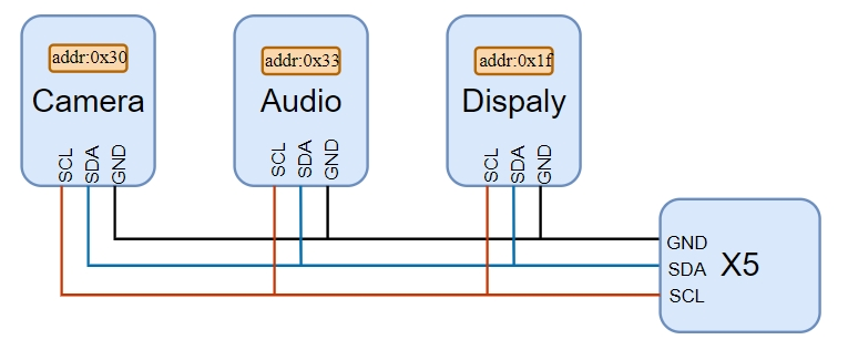
功能原理
I2C 总线
4.3.9.3. 驱动代码
drivers/i2c/i2c-dev.c 				# I2C 字符设备接口代码
drivers/i2c/i2c-core-base.c 			# I2C 框架代码
drivers/i2c/busses/i2c-designware-platdrv.c 	# I2C 驱动代码源文件
内核配置位置
/* arch/arm64/configs/hobot_x5_soc_defconfig */
CONFIG_I2C_CHARDEV=y 			# I2C 驱动应用层配置宏
CONFIG_I2C_DESIGNWARE_PLATFORM=y 	# DW I2C 驱动配置宏
内核 DTS 节点配置
X5 SOC 总共
X5 I2C 控制器arch/arm64/boot/dts/hobot/x5.dtsi 文件
备注:
x5.dtsi 中
4.3.9.4. I2C 使用
在
I2C Uboot 阶段使用
在 U-Boot 中,i2c 命令
输入 help i2c 可以
=> help i2c
i2c - I2C sub-system

Usage:
i2c bus [muxtype:muxaddr:muxchannel] - show I2C bus info
i2c crc32 chip address[.0, .1, .2] count - compute CRC32 checksum
i2c dev [dev] - show or set current I2C bus
i2c loop chip address[.0, .1, .2] [# of objects] - looping read of device
i2c md chip address[.0, .1, .2] [# of objects] - read from I2C device
i2c mm chip address[.0, .1, .2] - write to I2C device (auto-incrementing)
i2c mw chip address[.0, .1, .2] value [count] - write to I2C device (fill)
i2c nm chip address[.0, .1, .2] - write to I2C device (constant address)
i2c probe [address] - test for and show device(s) on the I2C bus
i2c read chip address[.0, .1, .2] length memaddress - read to memory
i2c write memaddress chip address[.0, .1, .2] length [-s] - write memory
          to I2C; the -s option selects bulk write in a single transaction
i2c flags chip [flags] - set or get chip flags
i2c olen chip [offset_length] - set or get chip offset length
i2c reset - re-init the I2C Controller
i2c speed [speed] - show or set I2C bus speed
1.显示 I2C 总线
=> i2c bus
Bus 0:  i2c@340d0000
2.选择
=> i2c dev 0
Setting bus to 0
3.通过 i2c probe 命令
=> i2c probe
Valid chip addresses: 1C
输出
4.设置 I2C 总线
查看
=> i2c speed
Current bus speed=100000
设置 I2C 总线
=> i2c speed 400000
Setting bus speed to 400000 Hz
5.读取 I2C 设备
使用 i2c md 命令
=> i2c md 0x1C 0x00 0x20
0000: 06 0f 0f c0 00 00 00 00 3f 33 61 0d 09 00 00 00    ........?3a.....
0010: ff 00 00 00 00 00 00 33 a0 15 a0 33 a0 24 dc 33    .......3...3.$.3
0x1C 是
6.向 I2C 设备
使用 i2c mw 命令
=> i2c mw 0x1C 0x00 06 1
0x1C 是
I2C Kernel 阶段使用
I2C 速度配置
默认
以
如果
需要 使用3.4MHz,需要 在 对应 板卡 对应 的 dts 的 i2c4 的 节点 内 配置 以下 参数: ... &i2c4 { status = "okay"; pinctrl-names = "default"; pinctrl-0 = <&pinctrl_i2c4>; clock-frequency = <3400000>; i2c-scl-falling-time-ns = <78>; i2c-sda-falling-time-ns = <78>; } ...
如果
需要 使用1MHz,需要 在 对应 板卡 对应 的 dts 的 i2c4 的 节点 内 配置 以下 参数: ... &i2c4 { status = "okay"; pinctrl-names = "default"; pinctrl-0 = <&pinctrl_i2c4>; clock-frequency = <1000000>; i2c-scl-falling-time-ns = <60>; i2c-sda-falling-time-ns = <60>; } ...
如果
需要 使用400kHz,需要 在 对应 板卡 对应 的 dts 的 i2c4 的 节点 内 配置 以下 参数: ... &i2c4 { status = "okay"; pinctrl-names = "default"; pinctrl-0 = <&pinctrl_i2c4>; clock-frequency = <400000>; i2c-scl-falling-time-ns = <190>; } ...
字
status: 表示
节点 状态,”okay” 表示 该 设备 启用,”disabled” 表示 设备 禁用。 pinctrl-names 和 pinctrl-0: 通过
引脚 控制 子系统(Pin Control)指定 该 I2C 控制器 所 使用 的 引脚 配置。 clock-frequency: 设置 I2C 总线
的 时钟 频率,单位 为 Hz。例如,<400000> 表示 400kHz。 i2c-scl-falling-time-ns 和 i2c-sda-falling-time-ns: 这
两个 参数 用于 配置 I2C 时钟 线(SCL)和 数据线(SDA)的 下降时间,单位 为 纳秒(ns)。
备注:
“i2c-scl-falling-time-ns”及“i2c-sda-falling-time-ns”这
I2C Slave 模式使用
概述
X5 的 I2C 控制器CONFIG_I2C_DESIGNWARE_SLAVE 后,可
注意:
同
一路 &i2cN节点下,不要同时 配置 Slave 模式 的 设备 节点 与 Master 模式 的 设备 节点;该路 控制器 应 专用 于 Slave 或 专用 于 Master。 Slave 模式
下 总线 时钟 由 外部 Master 提供,速率 与 上 拉 电阻 由 对方 板卡 与 硬件 设计 决定;X5 侧 只 需 保证 SCL/SDA/GND 正确 连接,两板 共地。
使用配置
本slave-eeprom 驱动
驱动
drivers/i2c/i2c-core-slave.c              # I2C Slave 核心层
drivers/i2c/busses/i2c-designware-slave.c # DW I2C Slave 控制器驱动
drivers/i2c/i2c-slave-eeprom.c            # 软件模拟 EEPROM 的 Slave 驱动
内核
在 arch/arm64/configs/hobot_x5_soc_defconfig 或 hobot_x5_soc_perf_defconfig 中
CONFIG_I2C=y                      # I2C 核心框架
CONFIG_I2C_CHARDEV=y              # 用户态 /dev/i2c-N(Master 板测试工具需要)
CONFIG_I2C_SLAVE=y                # Slave 模式框架
CONFIG_I2C_SLAVE_EEPROM=y         # slave-eeprom 配置
CONFIG_I2C_DESIGNWARE_PLATFORM=y  # DW I2C 控制器驱动
CONFIG_I2C_DESIGNWARE_SLAVE=y     # DW I2C Slave 支持
内核 DTS 节点
在
&i2c1 {
    status = "okay";
    snps,slave-sar-enable;

    eeprom_slave: eeprom@64 {
        compatible = "slave-24c02";
        reg = <0x40000064>;
    };
};
字
snps,slave-sar-enable:Slave 模式
下 使 控制器 在 总线 上 对 IC_SAR 所 配置 的 从机 地址 进行 应答(ACK)。 compatible:
slave-24c02表示模拟 256 字节 AT24C02;亦可 选用 slave-24c512等(可参考 i2c-slave-eeprom.c 驱动)。 reg:7 位
从机 地址 与 I2C_OWN_SLAVE_ADDRESS(1 << 30,即0x40000000)按位或,该 示例 7 位 地址 为 0x64,等价于 reg = <0x40000064>;其中I2C_OWN_SLAVE_ADDRES为开启 该 I2C 控制器 Slave 模式 的 标识。
功能测试
使用
1. Slave 板
确认
# cat /sys/bus/i2c/devices/i2c-1/name
Synopsys DesignWare I2C Slave adapter
向
# printf 'D-Robotics X5-EVB' | dd of=/sys/bus/i2c/devices/i2c-1/1-1064/slave-eeprom bs=1 seek=0 conv=notrunc
17+0 records in
17+0 records out
17 bytes copied, 0.0118063 s, 1.4 kB/s
#
# hexdump -C /sys/bus/i2c/devices/i2c-1/${SLAVE_DEV}/slave-eeprom
00000000  44 2d 52 6f 62 6f 74 69  63 73 20 58 35 2d 45 56  |D-Robotics X5-EV|
00000010  42 ff ff ff ff ff ff ff  ff ff ff ff ff ff ff ff  |B...............|
00000020  ff ff ff ff ff ff ff ff  ff ff ff ff ff ff ff ff  |................|
*
00000100
2. Master 板
扫描
# i2cdetect -y -r 1
     0  1  2  3  4  5  6  7  8  9  a  b  c  d  e  f
00:                         -- -- -- -- -- -- -- --
10: -- -- -- -- -- -- -- -- -- -- -- -- -- -- -- --
20: -- -- -- -- -- -- -- -- -- -- -- -- -- -- -- --
30: -- -- -- -- -- -- -- -- -- -- -- -- -- -- -- --
40: -- -- -- -- -- -- -- -- -- -- -- -- -- -- -- --
50: -- -- -- -- -- -- -- -- -- -- -- -- -- -- -- --
60: -- -- -- -- 64 -- -- -- -- -- -- -- -- -- -- --
70: -- -- -- -- -- -- -- --
读写b 表示
# 读偏移 0x00 的 1 字节
# i2cget -y 1 0x64 0x00 b
0x44
#

# 向偏移 0x00 写入 0x68 并回读
# i2cset -y 1 0x64 0x00 0x68
# i2cget -y 1 0x64 0x00
0x68
#
3. Slave 板
Master 写入
# hexdump -C /sys/bus/i2c/devices/i2c-1/${SLAVE_DEV}/slave-eeprom
00000000  68 2d 52 6f 62 6f 74 69  63 73 20 58 35 2d 45 56  |h-Robotics X5-EV|
00000010  42 ff ff ff ff ff ff ff  ff ff ff ff ff ff ff ff  |B...............|
00000020  ff ff ff ff ff ff ff ff  ff ff ff ff ff ff ff ff  |................|
*
00000100
User Space
通常,I2C 设备
下面
#include <stdio.h>
#include <stdint.h>
#include <string.h>
#include <stdlib.h>
#include <getopt.h>
#include <fcntl.h>
#include <unistd.h>
#include <sys/ioctl.h>
#include <linux/i2c.h>
#include <linux/i2c-dev.h>

/**
 * 打开指定的 I2C 总线设备文件
 */
static int open_i2c_bus(uint32_t bus)
{
	char filename[20];
	snprintf(filename, sizeof(filename), "/dev/i2c-%d", bus);
	int file = open(filename, O_RDWR);
	if (file < 0)
	{
		perror("Failed to open the I2C bus");
	}
	return file;
}

/**
 * 设置 I2C 地址
 */
static int set_i2c_address(int file, uint8_t i2c_addr)
{
	if (ioctl(file, I2C_SLAVE, i2c_addr) < 0)
	{
		perror("Failed to set I2C address");
		return -1;
	}
	return 0;
}

/**
 * I2C 读操作:16-bit 寄存器,16-bit 数据
 */
static int32_t i2c_read_reg16_data16(int file, uint8_t i2c_addr, uint16_t reg_addr, uint16_t *value)
{
	uint8_t sendbuf[2];
	uint8_t readbuf[2];
	struct i2c_rdwr_ioctl_data data;
	struct i2c_msg msgs[2];

	sendbuf[0] = (uint8_t)((reg_addr >> 8u) & 0xFF);
	sendbuf[1] = (uint8_t)(reg_addr & 0xFF);

	msgs[0].addr = i2c_addr;
	msgs[0].flags = 0; // 写操作
	msgs[0].len = 2;
	msgs[0].buf = sendbuf;

	msgs[1].addr = i2c_addr;
	msgs[1].flags = I2C_M_RD; // 读操作
	msgs[1].len = 2;
	msgs[1].buf = readbuf;

	data.msgs = msgs;
	data.nmsgs = 2;

	if (ioctl(file, I2C_RDWR, &data) < 0)
	{
		perror("Failed to read from the I2C bus");
		return -1;
	}

	*value = (uint16_t)((readbuf[0] << 8) | readbuf[1]);
	return 0;
}

/**
 * I2C 写操作:16-bit 寄存器,16-bit 数据
 */
static int32_t i2c_write_reg16_data16(int file, uint8_t i2c_addr, uint16_t reg_addr, uint16_t value)
{
	uint8_t sendbuf[4];

	sendbuf[0] = (uint8_t)((reg_addr >> 8u) & 0xFF);
	sendbuf[1] = (uint8_t)(reg_addr & 0xFF);
	sendbuf[2] = (uint8_t)((value >> 8u) & 0xFF);
	sendbuf[3] = (uint8_t)(value & 0xFF);

	if (write(file, sendbuf, sizeof(sendbuf)) != sizeof(sendbuf))
	{
		perror("Failed to write to the I2C bus");
		return -1;
	}

	return 0;
}

/**
 * I2C 读操作:16-bit 寄存器,8-bit 数据
 */
static int32_t i2c_read_reg16_data8(int file, uint8_t i2c_addr, uint16_t reg_addr, uint8_t *value)
{
	uint8_t sendbuf[2];
	uint8_t readbuf[1];
	struct i2c_rdwr_ioctl_data data;
	struct i2c_msg msgs[2];

	sendbuf[0] = (uint8_t)((reg_addr >> 8u) & 0xFF);
	sendbuf[1] = (uint8_t)(reg_addr & 0xFF);

	msgs[0].addr = i2c_addr;
	msgs[0].flags = 0; // 写操作
	msgs[0].len = 2;
	msgs[0].buf = sendbuf;

	msgs[1].addr = i2c_addr;
	msgs[1].flags = I2C_M_RD; // 读操作
	msgs[1].len = 1;
	msgs[1].buf = readbuf;

	data.msgs = msgs;
	data.nmsgs = 2;

	if (ioctl(file, I2C_RDWR, &data) < 0)
	{
		perror("Failed to read from the I2C bus");
		return -1;
	}

	*value = readbuf[0];
	return 0;
}

/**
 * I2C 写操作:16-bit 寄存器,8-bit 数据
 */
static int32_t i2c_write_reg16_data8(int file, uint8_t i2c_addr, uint16_t reg_addr, uint8_t value)
{
	uint8_t sendbuf[3];

	sendbuf[0] = (uint8_t)((reg_addr >> 8u) & 0xFF);
	sendbuf[1] = (uint8_t)(reg_addr & 0xFF);
	sendbuf[2] = value;

	if (write(file, sendbuf, sizeof(sendbuf)) != sizeof(sendbuf))
	{
		perror("Failed to write to the I2C bus");
		return -1;
	}

	return 0;
}

/**
 * 显示帮助信息
 */
void print_help(const char *prog_name)
{
	printf("Usage: %s [options]\n", prog_name);
	printf("Options:\n");
	printf("  -b, --bus <bus>        I2C bus number\n");
	printf("  -a, --addr <address>   I2C device address\n");
	printf("  -r, --reg <reg>        Register address\n");
	printf("  -v, --value <value>    Value to write\n");
	printf("  -w, --write            Write mode (default is read)\n");
	printf("  -x, --16bit            Use 16-bit data (default is 8-bit)\n");
	printf("  -h, --help             Show this help message\n");
}

/**
 * 主函数:处理用户输入和 I2C 操作
 */
int main(int argc, char **argv)
{

	uint32_t bus = 0;
	uint8_t i2c_addr = 0;
	uint16_t reg_addr = 0;
	uint16_t value16 = 0;
	uint8_t value8 = 0;
	int is_read = 1;  // 默认读操作
	int is_16bit = 0; // 默认 8-bit 数据

	static struct option long_options[] = {
		{"bus", required_argument, 0, 'b'},
		{"addr", required_argument, 0, 'a'},
		{"reg", required_argument, 0, 'r'},
		{"value", required_argument, 0, 'v'},
		{"write", no_argument, 0, 'w'},
		{"16bit", no_argument, 0, 'x'},
		{"help", no_argument, 0, 'h'},
		{0, 0, 0, 0}};
	int opt;
	while ((opt = getopt_long(argc, argv, "b:a:r:v:wxh", long_options, NULL)) != -1)
	{
		switch (opt)
		{
		case 'b':
			bus = strtoul(optarg, NULL, 0);
			break;
		case 'a':
			i2c_addr = (uint8_t)strtoul(optarg, NULL, 0);
			break;
		case 'r':
			reg_addr = (uint16_t)strtoul(optarg, NULL, 0);
			break;
		case 'v':
			if (is_16bit)
				value16 = (uint16_t)strtoul(optarg, NULL, 0);
			else
				value8 = (uint8_t)strtoul(optarg, NULL, 0);
			is_read = 0;
			break;
		case 'w':
			is_read = 0;
			break;
		case 'x':
			is_16bit = 1;
			break;
		case 'h':
		default:
			print_help(argv[0]);
			return 0;
		}
	}
	if (argc == 1) {
		print_help(argv[0]);
		return 0;
	}
	int file = open_i2c_bus(bus);
	if (file < 0)
		return -1;

	if (set_i2c_address(file, i2c_addr) < 0)
	{
		close(file);
		return -1;
	}

	if (is_read)
	{
		if (is_16bit)
		{
			if (i2c_read_reg16_data16(file, i2c_addr, reg_addr, &value16) == 0)
			{
				printf("Read 16-bit value: 0x%04X\n", value16);
			}
		}
		else
		{
			if (i2c_read_reg16_data8(file, i2c_addr, reg_addr, &value8) == 0)
			{
				printf("Read 8-bit value: 0x%02X\n", value8);
			}
		}
	}

	if (!is_read)
	{
		if (is_16bit)
		{
			if (i2c_write_reg16_data16(file, i2c_addr, reg_addr, value16) == 0)
			{
				printf("Wrote 16-bit value: 0x%04X\n", value16);
			}
		}
		else
		{
			if (i2c_write_reg16_data8(file, i2c_addr, reg_addr, value8) == 0)
			{
				printf("Wrote 8-bit value: 0x%02X\n", value8);
			}
		}
	}

	close(file);
	return 0;
}
测试
#读取 I2C 总线 7 上地址为 0x30 的设备中寄存器地址 0x3e01 的 8 位数据:
#./i2c_tool -b 7 -a 0x30 -r 0x3e01
Read 8-bit value: 0x02

#读取 I2C 总线 7 上地址为 0x30 的设备中寄存器地址 0x3e01 的 16 位数据:
#./i2c_tool -b 7 -a 0x30 -r 0x3e01 -x
Read 16-bit value: 0x0200

#向 I2C 总线 7 上地址为 0x30 的设备中寄存器地址 0x3e01 写入 8 位数据 0x1A
#./i2c_tool -b 7 -a 0x30 -r 0x3e01 -v 0x5A
Wrote 8-bit value: 0x5A

#向 I2C 总线 7 上地址为 0x30 的设备中寄存器地址 0x3e01 写入 16 位数据 0x1A10
#./i2c_tool -b 7 -a 0x30 -r 0x3e01 -v 0x1A10 -w -x
Wrote 16-bit value: 0x1A10
注意:当前
开源工具:i2c-tools
i2c-tools 是
i2cdetect — 用来
列举 I2C bus 及 该 bus 上 的 所有 设备 i2cdump — 显示 I2C 设备
的 所有 register 值 i2cget — 读取 I2C 设备
某个 register 的 值 i2cset — 写入 I2C 设备
某个 register 的 值 i2ctransfer — 可以
读、写 I2C 设备 某个 或者 多个 register 的 值
I2C Sysfs 频率控制节点
X5实现
root@buildroot:/# ls /sys/class/i2c-adapter/i2c-4/speed
/sys/class/i2c-adapter/i2c-4/speed
root@buildroot:~# ls /sys/class/i2c-adapter/i2c-4/scl-falling-time-ns
/sys/class/i2c-adapter/i2c-4/scl-falling-time-ns
root@buildroot:~# ls /sys/class/i2c-adapter/i2c-4/sda-falling-time-ns
/sys/class/i2c-adapter/i2c-4/sda-falling-time-ns
使用 cat 命令
root@buildroot:/# cat /sys/class/i2c-adapter/i2c-4/speed
100000
root@buildroot:~# cat /sys/class/i2c-adapter/i2c-4/scl-falling-time-ns
0ns
root@buildroot:~# cat /sys/class/i2c-adapter/i2c-4/sda-falling-time-ns
0ns
使用 echo 命令
root@buildroot:/# echo 400000 > /sys/class/i2c-adapter/i2c-4/speed
root@buildroot:/# cat /sys/class/i2c-adapter/i2c-4/speed
400000
修改 I2C 下降
root@buildroot:/# echo 190 > /sys/class/i2c-adapter/i2c-4/scl-falling-time-ns
root@buildroot:/# cat /sys/class/i2c-adapter/i2c-4/scl-falling-time-ns
190ns
注意:
操作 sysfs 速率
配置 节点不会修改 dts 内 配置 的“i2c-scl-falling-time-ns”以及“i2c-sda-falling-time-ns”。因此,在 修改 sysfs 节点 配置 速率 后,需要 根据 PCB 的 实际 情况,配置 scl-falling-time-ns 及 sda-falling-time-ns。 scl-falling-time-ns 及 sda-falling-time-ns 主要
作为 调试 节点 提供,推荐 用户 通过 DTS 配置 默认 参数,而 不是 直接 修改 sysfs 节点。 配置
不 正确 的 scl-falling-time-ns 和 sda-falling-time-ns 可能 导致 I2C 控制器无法 正常 ,请运作 谨慎 使用。
4.3.9.5. I2C 常见问题
在
驱动能力不足
问题
可能
I2C 控制器
当前 配置 的 驱动 能力 不足,无法 提供 足够 的 电流 拉低 i2c 信号线。 硬件
上拉 电阻 配置 不合理,阻值 过低,影响 了 I2C 的 下 拉 电平。
排查
示波器
观测 波形: 通过
示波器 检测 I2C 信号 波形,重点 查看 信号 是否 能够 被 有效 拉低 到 逻辑 低电平,根据 主从 设备 阈值 并 留有 一定 裕量。
检查
硬件 电阻 配置: 确认 SDA 和 SCL 信号线
上拉 电阻 的 阻值,推荐值 为 速率 <=400Kb/s 时,使用2.2K、4.7K 上拉;速率 > 400Kb/s 时,使用1K 上拉;若 发现 问题,可以 尝试 减小 上拉 电阻值,以 平衡 i2c 下 拉 能力。
解决方案:
修改
设备树 增加 驱动 能力,以 i2c4为例 参照 修改,并 修改 字 段 drive-strength。
pconf_drv_pu_ds4_1v8: pconf-dev-pu-ds4-1v8 {
	bias-pull-up;
	power-source = <HORIZON_IO_PAD_VOLTAGE_1V8>;
	drive-strength = <4>;
};

&i2c4grp {
	horizon,pins = <
		LSIO_I2C4_SCL  LSIO_PINMUX_3 BIT_OFFSET0  MUX_ALT0 &pconf_drv_pu_ds4_1v8
		LSIO_I2C4_SDA  LSIO_PINMUX_3 BIT_OFFSET2  MUX_ALT0 &pconf_drv_pu_ds4_1v8
	>;
};
优化
上拉 电阻: 根据 实际 的 波形 情况,调整 SDA 和 SCL 线 的 上 拉 电阻,减小 上拉 阻值 以 提升 信号 的 驱动 能力。
设备供电时序异常
问题
可能
从
设备 的 供电 初始化 时序 错误 或 较慢,导致 设备 未 准备 好 就 被 主 设备 访问。
排查
检测
从 设备 供电 时序: 使用
示波器 或 逻辑 分析仪 观察 从 设备 的 上 电 时序,确认 供电 是否 稳定,是否 符合 Spec 的 要求。
确认
从 设备 工作 状态: 使用 i2cdetect 工具
扫描 I2C 总线,验证 从 设备 是否 能 被 正常 检测 到:
i2cdetect -y 4 # 4为 I2C 控制器实际编号
如果
解决方案:
从
设备 上电 时序 由主 设备 控制 时,需要 确认 上电 时序 是否 符合要求,并 确保 从 设备 初始化 完成 后 再启动 I2C 通信。