3.15. sample_pipeline Usage Instructions
3.15.1. Overview
3.15.1.1. Function Introduction
sample_pipeline is used to implement one or multiple sensor pipeline cascades, supporting common pipeline scenarios for users. Users can explore the construction methods of various pipelines through the subdirectories under sample_pipeline.
Note: When an HDR sensor is connected, the VIN-ISP connection must use online mode. Since online mode exclusively occupies the ISP resource, only 1 stream is supported.
3.15.1.2. Architecture Description of sample_pipeline
sample_pipeline contains multiple test cases, each existing as a subdirectory under app/samples/platform_samples/sample_pipeline. Each subdirectory is described as follows:
| Directory | Description |
|---|---|
| common | Common operation functions, not elaborated in this section |
| single_pipe_vin_isp_vse | Example of a single sensor simple pipeline cascade |
| single_pipe_vin_isp_vse_vpu | Example of a single sensor simple pipeline cascade with encoding |
| single_pipe_vin_isp_gdc | Example of GDC processing with a single sensor |
| single_pipe_vin_isp_vse_gdc | Example of a single sensor pipeline with VSE followed by GDC dynamic binbuf switching |
| multi_pipe_vin_isp_vse | Example of multiple sensor pipelines cascaded with encoding |
| multi_pipe_crop_and_stitch | Test case for multi-sensor cropping and stitching |
| multi_pipe_gdc_stitching | Test case for stitching two sensor inputs |
| multi_pipe_vin_isp_vse_gpu2d | Example of two sensor pipelines with GPU rotation |
| sample_custom_capbuf | Test processing latency of VSE / GDC under different configurations |
| uvc_gadget_camera | Virtual UVC test case |
| uvc_capture_sample | UVC camera capture example |
| mp4_decode_and_display | Use case for displaying MP4 files via HDMI after decoding through the VPU |
| single_pipe_vin_isp_vse_gpu2d | Test a single video pipeline from Sensor → VIN → ISP → VSE → GPU2D |
| single_pipe_vin_isp_vse_vo | Example for verifying single-channel video capture and display functionality |
| single_format_convert_gpu2d | Test example program for verifying image format conversion using 2D GPU |
| single_pipe_vin_isp_vse_multi_process | Multi-process communication example for single sensor pipeline |
| single_pipe_vin_isp_vse_bpu | Example of algorithm inference pathway from sensor image data to BPU |
3.15.2. single_pipe_vin_isp_vse
3.15.2.1. Functional Overview
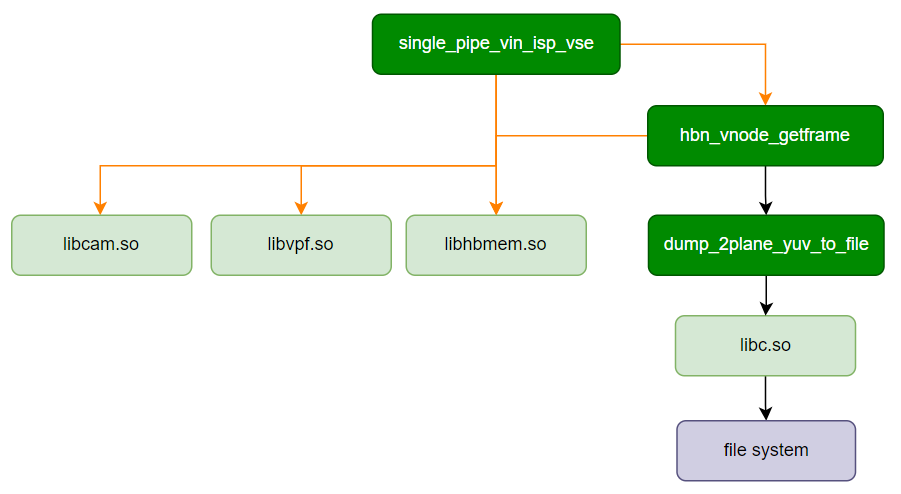
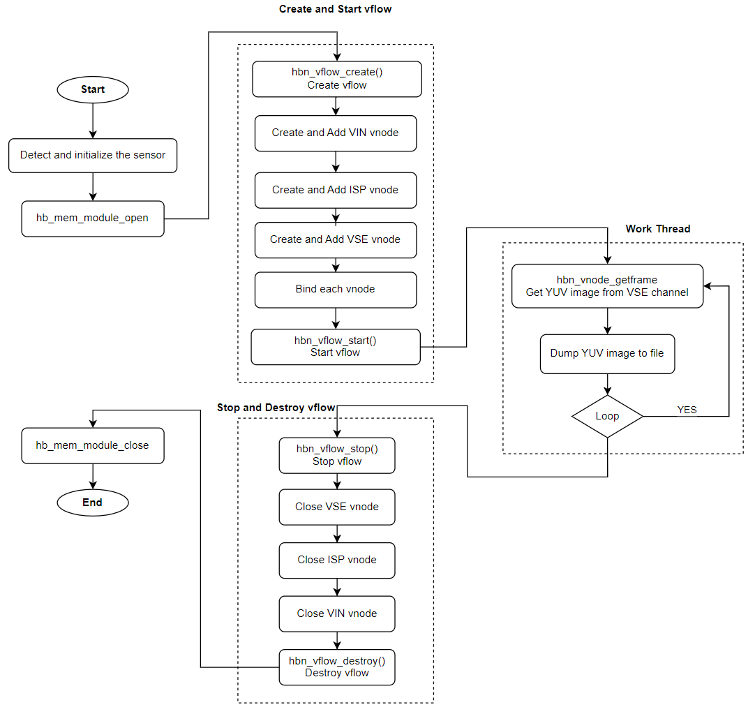
The single_pipe_vin_isp_vse example cascades the MIPI CSI, VIN, ISP, and VSE modules. It is one of the most basic examples demonstrating the connection of modules in a video pipeline. Users can refer to this example to understand the creation methods of vnode and vflow.
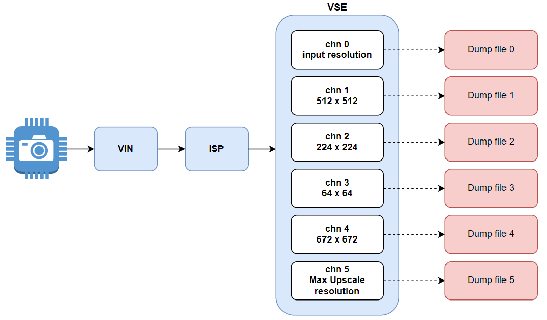
After the Camera Sensor image passes through VIN and ISP processing, it reaches the VSE module. The VSE module is configured with six output channels as follows:
Channel 0: Outputs the original resolution image after ISP processing.
Channel 1: Outputs a commonly used algorithm image resolution of 512 x 512, aligned to 16 pixels.
Channel 2: Outputs a commonly used algorithm image resolution of 224 x 224, not aligned to 16 pixels.
Channel 3: Outputs an image with width and height each cropped by half around the original center point. The output width and height equal the ROI region dimensions, scaled down to the supported minimum resolution: 64 x 64.
Channel 4: Outputs a commonly used algorithm image resolution: 672 x 672.
Channel 5: Outputs an image scaled up to the maximum supported resolution (Note: Images can be scaled up to 4x maximum, and only this channel supports scaling up): 4096 x 3076.
Software Architecture Description
Data Flow Description
Code Location and Directory Structure
Code location:
app/samples/platform_samples/sample_pipeline/single_pipe_vin_isp_vseDirectory structure
single_pipe_vin_isp_vse
├── Makefile
├── single_pipe_vin_isp_vse
└── single_pipe_vin_isp_vse.c
API Flow Description
3.15.2.2. Compilation and Deployment
Compilation
Enter the
single_pipe_vin_isp_vsedirectory and executemaketo compile.The output artifact is
single_pipe_vin_isp_vselocated in the source directory.For detailed compilation methods, please refer to the Compilation Methods section.
Program Deployment
After uploading single_pipe_vin_isp_vse to the development board, run the command chmod +x single_pipe_vin_isp_vse to grant executable permissions.
3.15.2.3. Running
Running Method
Directly execute the program ./single_pipe_vin_isp_vse to obtain help information.
Program Parameter Options
Usage: ./single_pipe_vin_isp_vse [OPTIONS]
Options:
  -s <sensor_index>             Specify sensor index
  -c <channel_type>             Specify channel type: vo and vf and io and if, default: vf:if
                Support both individual configuration and combined configuration.
                The individual configuration supports four types:
                                1. vo: vin online isp
                                2. vf: vin offline isp
                                3. io: isp online vse
                                4. if: isp offline vse
                The combination configuration supports four types:
                                1. vo:io  vin online isp + isp online vse
                                2. vo:if  vin online isp + isp offline vse
                                3. vf:io  vin offline isp + isp online vse
                                4. vf:if  vin offline isp + isp offline vse
  -h    Show help message
Parameter Description:
-s: Specify the Camera Sensor model and configuration.-c: Specify the connection methods between the designated VIN and ISP, and between the ISP and VSE, supporting both offline and online connection modes respectively.
Running Results
single_pipe_vin_isp_vse saves one NV12 image from each output channel every 60 frames into the current running directory.
Example: Using sc230ai as the sensor input, execute ./single_pipe_vin_isp_vse -s 3. Please select the corresponding index based on the currently connected sensor.
Using index:3  sensor_name:sc230ai-30fps  config_file:linear_1920x1080_raw10_30fps_1lane.c
[INFO] board_id is 0x0202, not need skip sci1.
mipi mclk is configed.
Searching camera sensor on device: /proc/device-tree/soc/cam/vcon@0 i2c bus: 4 mipi rx phy: 0
INFO: Found sensor_name:sc230ai-30fps on mipi rx csi 0, i2c addr 0x30, config_file:linear_1920x1080_raw10_30fps_1lane.c
hbn_vnode_set_ochn_attr: 0, 1920x1080
hbn_vnode_set_ochn_attr: 1, 512x512
hbn_vnode_set_ochn_attr: 2, 224x224
hbn_vnode_set_ochn_attr: 3, 64x64
hbn_vnode_set_ochn_attr: 4, 672x672
hbn_vnode_set_ochn_attr: 5, 3840x2160
[  353.381931] hobot-sif 3d020000.sif: sif frame size incorrect, hsize count:0x780 vsize count:0x0 for inst:0
[  353.414876] hobot-sif 3d020000.sif: sif frame size incorrect, hsize count:0x780 vsize count:0x438 for inst:0
####################### vse chn 0 #######################
=== Frame Info ===
Frame ID: 0
Timestamps: 353357434335
Systimestamps: 353357434418
tv: 0.000000
trig_tv: 0.000000
Frame Done: 8
Buffer Index: 0

=== Graphic Buffer ===
File Descriptors: 23 -1 -1
Plane Count: 2
Format: 8
Width: 1920
Height: 1080
Stride: 1920
Vertical Stride: 1080
Is Contiguous: 1
Share IDs: 44 0 0
Flags: 67108881
Sizes: 2073600 1036800 0
Virtual Addresses: 0xffffbd120000 0xffffbd31a400 (nil)
Physical Addresses: 2795712512 2797786112 0
Offsets: 0 0 0
####################### vse chn 1 #######################
=== Frame Info ===
Frame ID: 0
Timestamps: 353357434335
Systimestamps: 353357434418
tv: 0.000000
trig_tv: 0.000000
Frame Done: 8
Buffer Index: 0

=== Graphic Buffer ===
File Descriptors: 29 -1 -1
Plane Count: 2
Format: 8
Width: 512
Height: 512
Stride: 512
Vertical Stride: 512
Is Contiguous: 1
Share IDs: 50 0 0
Flags: 67108881
Sizes: 262144 131072 0
Virtual Addresses: 0xffffbcad0000 0xffffbcb10000 (nil)
Physical Addresses: 2805063680 2805325824 0
Offsets: 0 0 0
####################### vse chn 2 #######################
=== Frame Info ===
Frame ID: 0
Timestamps: 353357434335
Systimestamps: 353357434418
tv: 0.000000
trig_tv: 0.000000
Frame Done: 8
Buffer Index: 0

=== Graphic Buffer ===
File Descriptors: 35 -1 -1
Plane Count: 2
Format: 8
Width: 224
Height: 224
Stride: 224
Vertical Stride: 224
Is Contiguous: 1
Share IDs: 56 0 0
Flags: 67108881
Sizes: 50176 25088 0
Virtual Addresses: 0xffffbc9fd000 0xffffbca09400 (nil)
Physical Addresses: 2806255616 2806305792 0
Offsets: 0 0 0
####################### vse chn 3 #######################
=== Frame Info ===
Frame ID: 0
Timestamps: 353357434335
Systimestamps: 353357434418
tv: 0.000000
trig_tv: 0.000000
Frame Done: 8
Buffer Index: 0

=== Graphic Buffer ===
File Descriptors: 41 -1 -1
Plane Count: 2
Format: 8
Width: 64
Height: 64
Stride: 64
Vertical Stride: 64
Is Contiguous: 1
Share IDs: 62 0 0
Flags: 67108881
Sizes: 4096 2048 0
Virtual Addresses: 0xffffbdfa9000 0xffffbdfaa000 (nil)
Physical Addresses: 2806501376 2806505472 0
Offsets: 0 0 0
####################### vse chn 4 #######################
=== Frame Info ===
Frame ID: 0
Timestamps: 353357434335
Systimestamps: 353357434418
tv: 0.000000
trig_tv: 0.000000
Frame Done: 8
Buffer Index: 0

=== Graphic Buffer ===
File Descriptors: 47 -1 -1
Plane Count: 2
Format: 8
Width: 672
Height: 672
Stride: 672
Vertical Stride: 672
Is Contiguous: 1
Share IDs: 68 0 0
Flags: 67108881
Sizes: 451584 225792 0
Virtual Addresses: 0xffffbc931000 0xffffbc99f400 (nil)
Physical Addresses: 2806538240 2806989824 0
Offsets: 0 0 0
####################### vse chn 5 #######################
=== Frame Info ===
Frame ID: 0
Timestamps: 353357434335
Systimestamps: 353357434418
tv: 0.000000
trig_tv: 0.000000
Frame Done: 8
Buffer Index: 0

=== Graphic Buffer ===
File Descriptors: 53 -1 -1
Plane Count: 2
Format: 8
Width: 3840
Height: 2160
Stride: 3840
Vertical Stride: 2160
Is Contiguous: 1
Share IDs: 74 0 0
Flags: 67108881
Sizes: 8294400 4147200 0
Virtual Addresses: 0xffffbbc07000 0xffffbc3f0000 (nil)
Physical Addresses: 2808590336 2816884736 0
Offsets: 0 0 0
The following files will be saved during execution:
vse_ch0_0.yuv
vse_ch1_0.yuv
vse_ch2_0.yuv
vse_ch3_0.yuv
vse_ch4_0.yuv
vse_ch5_0.yuv
vse_ch0_60.yuv
vse_ch1_60.yuv
vse_ch2_60.yuv
vse_ch3_60.yuv
vse_ch4_60.yuv
vse_ch5_60.yuv
... ...
3.15.3. single_pipe_vin_isp_vse_vpu
3.15.3.1. Functional Overview
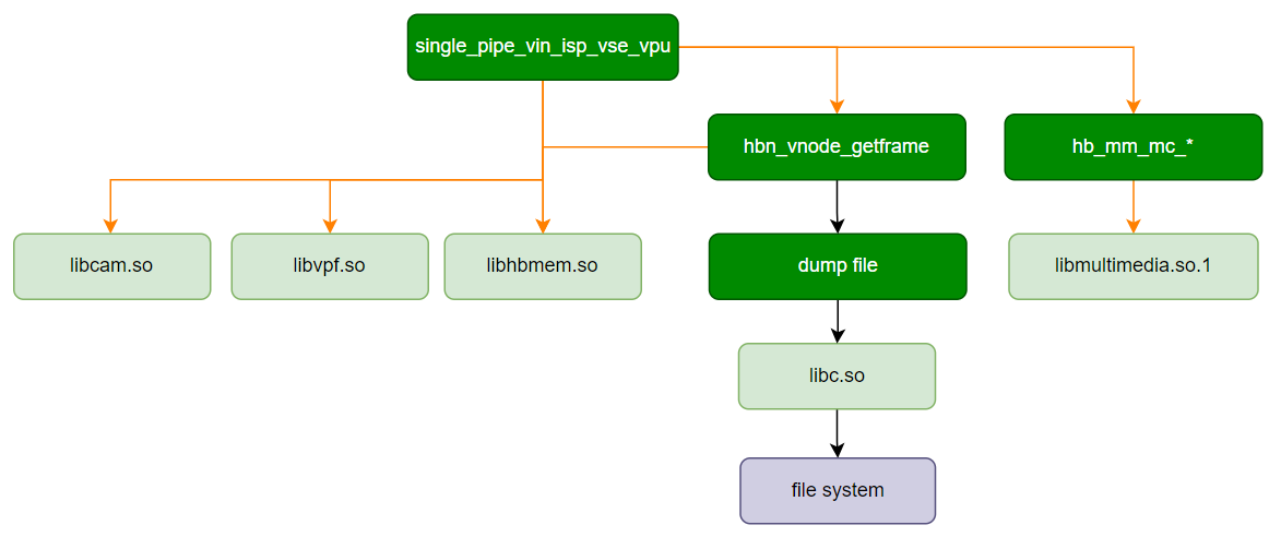
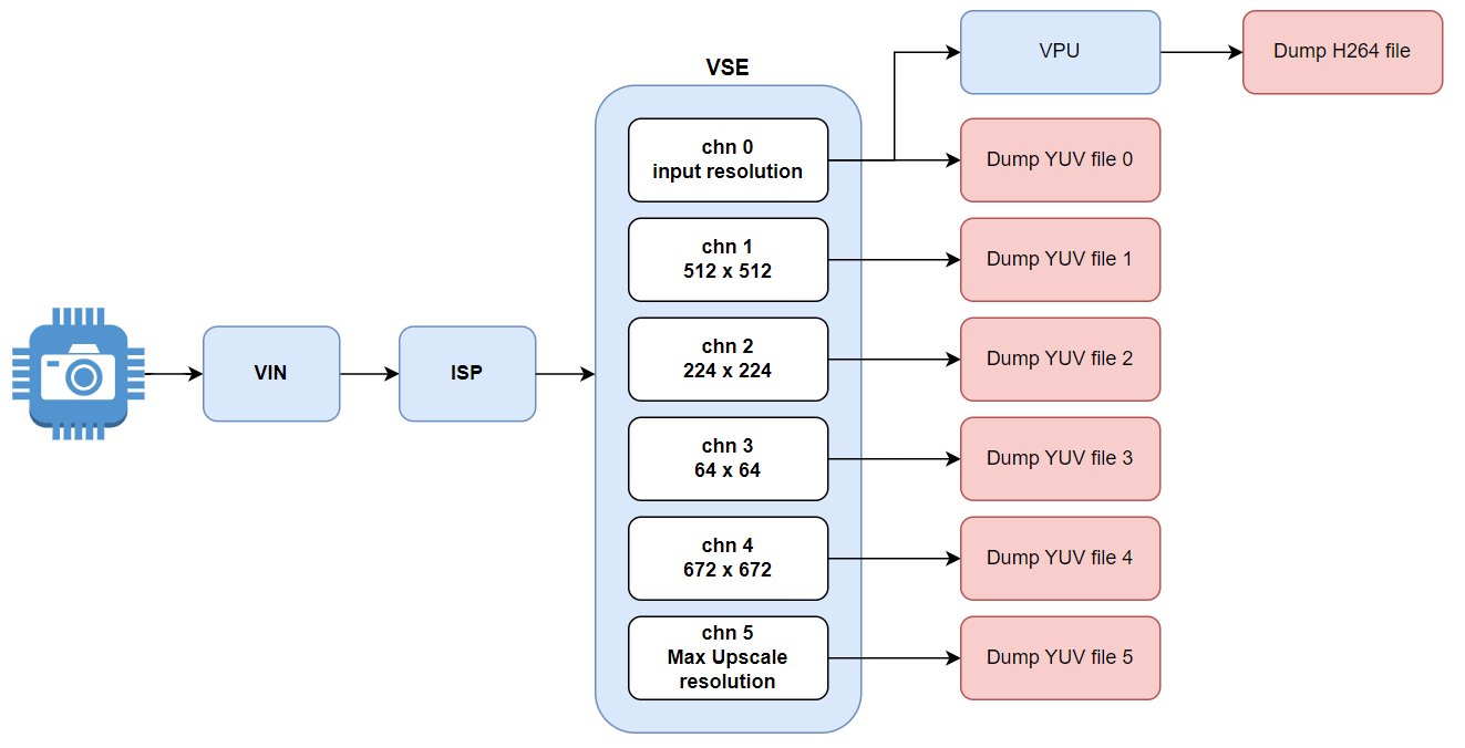
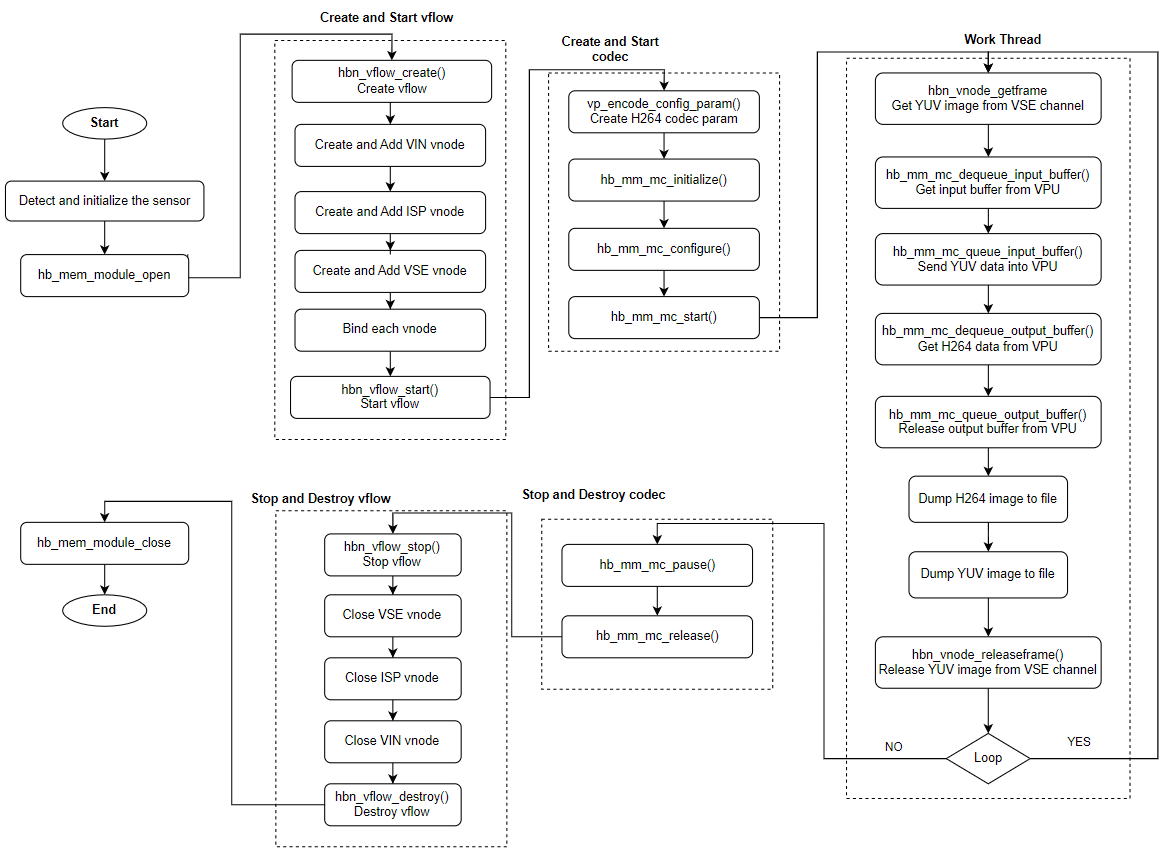
The single_pipe_vin_isp_vse_vpu example cascades the MIPI CSI, VIN, ISP, VSE, and CODEC modules, forming one of the most basic module cascading examples. After the Camera Sensor image undergoes VIN and ISP processing, it reaches the VSE module. The VSE module is configured with six output channels as follows:
Channel 0: Outputs the original resolution image after ISP processing. The output from this channel is further sent to the encoder and saved as an H.264 video stream.
Channel 1: Outputs a commonly used algorithm image resolution of 512 x 512, aligned to 16 pixels.
Channel 2: Outputs a commonly used algorithm image resolution of 224 x 224, not aligned to 16 pixels.
Channel 3: Outputs an image with width and height each cropped by half around the original center point. The output width and height equal the ROI region dimensions, scaled down to the supported minimum resolution: 64 x 64.
Channel 4: Outputs a commonly used algorithm image resolution: 672 x 672.
Channel 5: Outputs an image scaled up to the maximum supported resolution (Note: Images can be scaled up to 4x maximum): 4096 x 3076.
Software Architecture Description
Data Flow Description
Code Location and Directory Structure
Code location:
app/samples/platform_samples/sample_pipeline/single_pipe_vin_isp_vse_vpuDirectory structure
single_pipe_vin_isp_vse_vpu
├── Makefile
├── single_pipe_vin_isp_vse_vpu
└── single_pipe_vin_isp_vse_vpu.c
API Flow Description
3.15.3.2. Compilation and Deployment
Compilation
Enter the
single_pipe_vin_isp_vse_vpudirectory and executemaketo compile.The output artifact is
single_pipe_vin_isp_vse_vpulocated in the source directory.For detailed compilation methods, please refer to the Compilation Methods section.
Program Deployment
After uploading single_pipe_vin_isp_vse_vpu to the development board, run the command chmod +x single_pipe_vin_isp_vse_vpu to grant executable permissions.
3.15.3.3. Running
Running Method
Directly execute the program ./single_pipe_vin_isp_vse_vpu to obtain help information.
Program Parameter Options
Usage: ./single_pipe_vin_isp_vse_vpu [OPTIONS]
Options:
  -s <sensor_index>             Specify sensor index
  -c <channel_type>             Specify channel type: vo and vf and io and if, default: vf:if
                Support both individual configuration and combined configuration.
                The individual configuration supports four types:
                                1. vo: vin online isp
                                2. vf: vin offline isp
                                3. io: isp online vse
                                4. if: isp offline vse
                The combination configuration supports four types:
                                1. vo:io  vin online isp + isp online vse
                                2. vo:if  vin online isp + isp offline vse
                                3. vf:io  vin offline isp + isp online vse
                                4. vf:if  vin offline isp + isp offline vse
Parameter Description:
-s: Specify the Camera Sensor model and configuration.-c: Specify the connection methods between the designated VIN and ISP, and between the ISP and VSE, supporting both offline and online connection modes respectively.
Running Results
single_pipe_vin_isp_vse_vpu saves one NV12 image from each output channel every 60 frames into the current running directory and saves the H.264 encoded file from VSE channel 0.
Example: Using sc230ai as the sensor input, execute ./single_pipe_vin_isp_vse_vpu -s 3. Please select the corresponding index based on the currently connected sensor.
Sample log output is shown below:
# ./single_pipe_vin_isp_vse_vpu -s 3
Using index:3  sensor_name:sc230ai-30fps  config_file:linear_1920x1080_raw10_30fps_1lane.c
[INFO] board_id is 0x0202, not need skip sci1.
mipi mclk is configed.
Searching camera sensor on device: /proc/device-tree/soc/cam/vcon@0 i2c bus: 4 mipi rx phy: 0
INFO: Found sensor_name:sc230ai-30fps on mipi rx csi 0, i2c addr 0x30, config_file:linear_1920x1080_raw10_30fps_1lane.c
hbn_vnode_set_ochn_attr: 0, 1920x1080
hbn_vnode_set_ochn_attr: 1, 512x512
hbn_vnode_set_ochn_attr: 2, 224x224
hbn_vnode_set_ochn_attr: 3, 64x64
hbn_vnode_set_ochn_attr: 4, 672x672
hbn_vnode_set_ochn_attr: 5, 3840x2160
[   34.670395] hobot-sif 3d020000.sif: sif frame size incorrect, hsize count:0x780 vsize count:0x0 for inst:0
[   34.703353] hobot-sif 3d020000.sif: sif frame size incorrect, hsize count:0x780 vsize count:0x438 for inst:0
Encode idx: 0, init successful
lunch read_vse_data thread
count:0
####################### vse chn 0 #######################
=== Frame Info ===
Frame ID: 0
Timestamps: 34646123641
Systimestamps: 34646123724
tv: 0.000000
trig_tv: 0.000000
Frame Done: 8
Buffer Index: 0

=== Graphic Buffer ===
File Descriptors: 23 -1 -1
Plane Count: 2
Format: 8
Width: 1920
Height: 1080
Stride: 1920
Vertical Stride: 1080
Is Contiguous: 1
Share IDs: 44 0 0
Flags: 67108881
Sizes: 2073600 1036800 0
Virtual Addresses: 0xffff90d80000 0xffff90f7a400 (nil)
Physical Addresses: 2795712512 2797786112 0
Offsets: 0 0 0
####################### vse chn 1 #######################
=== Frame Info ===
Frame ID: 0
Timestamps: 34646123641
Systimestamps: 34646123724
tv: 0.000000
trig_tv: 0.000000
Frame Done: 8
Buffer Index: 0

=== Graphic Buffer ===
File Descriptors: 39 -1 -1
Plane Count: 2
Format: 8
Width: 512
Height: 512
Stride: 512
Vertical Stride: 512
Is Contiguous: 1
Share IDs: 60 0 0
Flags: 67108881
Sizes: 262144 131072 0
Virtual Addresses: 0xffff8f858000 0xffff8f898000 (nil)
Physical Addresses: 2820648960 2820911104 0
Offsets: 0 0 0
####################### vse chn 2 #######################
=== Frame Info ===
Frame ID: 0
Timestamps: 34646123641
Systimestamps: 34646123724
tv: 0.000000
trig_tv: 0.000000
Frame Done: 8
Buffer Index: 0

=== Graphic Buffer ===
File Descriptors: 55 -1 -1
Plane Count: 2
Format: 8
Width: 224
Height: 224
Stride: 224
Vertical Stride: 224
Is Contiguous: 1
Share IDs: 76 0 0
Flags: 67108881
Sizes: 50176 25088 0
Virtual Addresses: 0xffff8f5a5000 0xffff8f5b1400 (nil)
Physical Addresses: 2823827456 2823877632 0
Offsets: 0 0 0
####################### vse chn 3 #######################
=== Frame Info ===
Frame ID: 0
Timestamps: 34646123641
Systimestamps: 34646123724
tv: 0.000000
trig_tv: 0.000000
Frame Done: 8
Buffer Index: 0

=== Graphic Buffer ===
File Descriptors: 71 -1 -1
Plane Count: 2
Format: 8
Width: 64
Height: 64
Stride: 64
Vertical Stride: 64
Is Contiguous: 1
Share IDs: 92 0 0
Flags: 67108881
Sizes: 4096 2048 0
Virtual Addresses: 0xffff91d95000 0xffff91d96000 (nil)
Physical Addresses: 2824482816 2824486912 0
Offsets: 0 0 0
####################### vse chn 4 #######################
=== Frame Info ===
Frame ID: 0
Timestamps: 34646123641
Systimestamps: 34646123724
tv: 0.000000
trig_tv: 0.000000
Frame Done: 8
Buffer Index: 0

=== Graphic Buffer ===
File Descriptors: 87 -1 -1
Plane Count: 2
Format: 8
Width: 672
Height: 672
Stride: 672
Vertical Stride: 672
Is Contiguous: 1
Share IDs: 108 0 0
Flags: 67108881
Sizes: 451584 225792 0
Virtual Addresses: 0xffff8f47a000 0xffff8f4e8400 (nil)
Physical Addresses: 2824581120 2825032704 0
Offsets: 0 0 0
####################### vse chn 5 #######################
=== Frame Info ===
Frame ID: 0
Timestamps: 34646123641
Systimestamps: 34646123724
tv: 0.000000
trig_tv: 0.000000
Frame Done: 8
Buffer Index: 0

=== Graphic Buffer ===
File Descriptors: 103 -1 -1
Plane Count: 2
Format: 8
Width: 3840
Height: 2160
Stride: 3840
Vertical Stride: 2160
Is Contiguous: 1
Share IDs: 124 0 0
Flags: 67108881
Sizes: 8294400 4147200 0
Virtual Addresses: 0xffff8e412000 0xffff8ebfb000 (nil)
Physical Addresses: 2830053376 2838347776 0
Offsets: 0 0 0
...
The program will generate the following files at runtime:
single_pipe_vin_isp_vse_vpu.h264
vse_ch0_0.yuv
vse_ch1_0.yuv
vse_ch2_0.yuv
vse_ch3_0.yuv
vse_ch4_0.yuv
vse_ch5_0.yuv
vse_ch0_60.yuv
vse_ch1_60.yuv
vse_ch2_60.yuv
vse_ch3_60.yuv
vse_ch4_60.yuv
vse_ch5_60.yuv
... ...
3.15.4. single_pipe_vin_isp_gdc
3.15.4.1. Function Overview
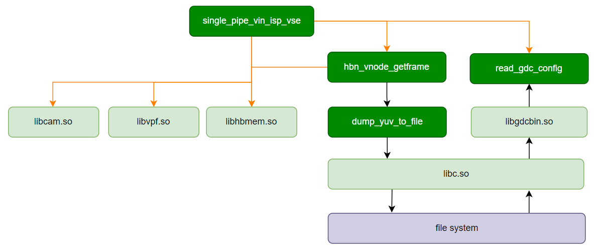
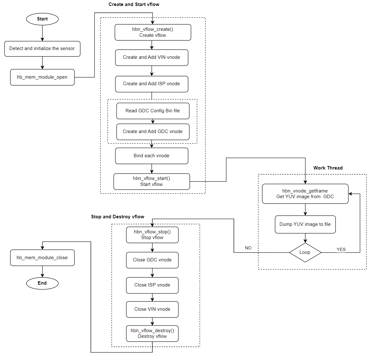
single_pipe_vin_isp_gdc demonstrates the configuration and execution of a single video input (VIN) pipeline through Image Signal Processing (ISP) and Geometric Distortion Correction (GDC).
This sample program initializes the Camera Sensor, establishes a video pipeline to GDC, and routes the ISP-processed image data to two GDC instances for further processing.
Software Architecture Description
Data Flow Description

Code Location and Directory Structure
Code location:
app/samples/platform_samples/sample_pipeline/single_pipe_vin_isp_gdcDirectory structure
single_pipe_vin_isp_gdc
├── Makefile
├── single_pipe_vin_isp_gdc
└── single_pipe_vin_isp_gdc.c
API Flow Description
3.15.4.2. Build and Deployment
Build
Enter the
single_pipe_vin_isp_gdcdirectory and runmaketo compile.The output binary is
single_pipe_vin_isp_gdclocated in the source directory.For detailed build instructions, refer to the Build Method section.
Program Deployment
After uploading single_pipe_vin_isp_gdc and the corresponding GDC BIN file for the sensor to the development board, run the command chmod +x single_pipe_vin_isp_gdc to grant execution permissions.
3.15.4.3. Run
How to Run the Program
Executing ./single_pipe_vin_isp_gdc directly displays the help message.
Program Option Descriptions
Usage: single_pipe_vin_isp_gdc [OPTIONS]
Options:
  -s <sensor_index>             Specify sensor index
  -c <channel_type>             Specify channel type: vo and vf
                                        1. vo: vin online isp
                                        2. vf: vin offline isp
                                        3. default is vf
  -f <gdc_bin_file>      Specify sensor gdc_bin_file path
  -h                     Show this help message
-s <sensor_index>Specifies the
Camera Sensorindex.Example:
-s 0uses the sensor with index 0.
-c:Specify the connection method between the VIN and ISP, supporting both offline and online connection modes.
Example:
-c vodenotes VIN online ISP
-f <gdc_bin_file>Specifies the path to the GDC configuration binary file.
Example:
-f /path/to/gdc.binuses the GDC binary file at the specified path.
-hDisplays help information. Running this command outputs detailed descriptions of the above options.
Runtime Behavior
This section demonstrates the usage of single_pipe_vin_isp_gdc using the sc230ai sensor as an example.
Run the following command:
./single_pipe_vin_isp_gdc -s 3 -f sc230ai_gdc.bin
Notes
The GDC bin file must be specifically calibrated for each
Camera Sensor. This sample code typically uses pre-configured files from thevp_sensors/gdc_bindirectory. To add or modify GDC bin files, refer to the sample_gdc example for instructions on GDC usage.
Example log output:
 ./single_pipe_vin_isp_gdc -s 3 -f sc230ai_gdc.bin
Using index:3  sensor_name:sc230ai-30fps  config_file:linear_1920x1080_raw10_30fps_1lane.c
[INFO] board_id is 202, so skip sci1.
Searching camera sensor on device: /proc/device-tree/soc/cam/vcon@0 i2c bus: 4 mipi rx phy: 0
Searching camera sensor on device: /proc/device-tree/soc/cam/vcon@2 i2c bus: 2 mipi rx phy: 2
WARN: Sensor Name: sc230ai-30fps, Expected Chip ID: 0xCB34, Actual Chip ID Read: 0x01
Searching camera sensor on device: /proc/device-tree/soc/cam/vcon@3 i2c bus: 7 mipi rx phy: 3
INFO: Found sensor_name:sc230ai-30fps on mipi rx csi 3, i2c addr 0x30, config_file:linear_1920x1080_raw10_30fps_1lane.c

***************  Command Lists  ***************
 g      -- get single frame
 l      -- get a set frames
 q      -- quit
 h      -- print help message

Command:
Command Explanation:
g: Retrieves images from the output channels of both GDC instances. Multiple ‘g’ inputs allow continuous image capture (e.g., typing
gggg).
Command: g
gdc(165733) dump yuv 1920x1080(stride:1920), buffer size: 2073600 + 1036800 frame id: 4612, timestamp: 45479310356561
isp dump yuv 1920x1080(stride:1920), buffer size: 2073600 + 1036800 frame id: 5490, timestamp: 45508577025491
gdc(231269) dump yuv 1920x1080(stride:1920), buffer size: 2073600 + 1036800 frame id: 5490, timestamp: 45508577025491
l: Continuously captures 12 frames, retrieving one image from each GDC output channel per capture (equivalent to entering 12 ‘g’ commands).
Command: l
gdc(165733) dump yuv 1920x1080(stride:1920), buffer size: 2073600 + 1036800 frame id: 4613, timestamp: 45479343689602
isp dump yuv 1920x1080(stride:1920), buffer size: 2073600 + 1036800 frame id: 5522, timestamp: 45509643692158
gdc(231269) dump yuv 1920x1080(stride:1920), buffer size: 2073600 + 1036800 frame id: 5522, timestamp: 45509643692158
... (omitted, total 12 frames dumped) ...
gdc(165733) dump yuv 1920x1080(stride:1920), buffer size: 2073600 + 1036800 frame id: 5532, timestamp: 45509977023200
isp dump yuv 1920x1080(stride:1920), buffer size: 2073600 + 1036800 frame id: 5533, timestamp: 45510010356909
gdc(231269) dump yuv 1920x1080(stride:1920), buffer size: 2073600 + 1036800 frame id: 5533, timestamp: 45510010356909
q: Exits the program.
Command: q
quit
3.15.5. single_pipe_vin_isp_vse_gdc
3.15.5.1. Function Overview
single_pipe_vin_isp_vse_gdc demonstrates the cascade of VIN, ISP, VSE, and GDC modules in a single video pipeline, as well as dynamic switching of GDC binbuf.
This example supports the following link configurations:
VIN -> ISP: Supports online / offlineISP -> VSE: Supports online / offlineVSE -> GDC: Supports offline only (VSE outputs to DDR)
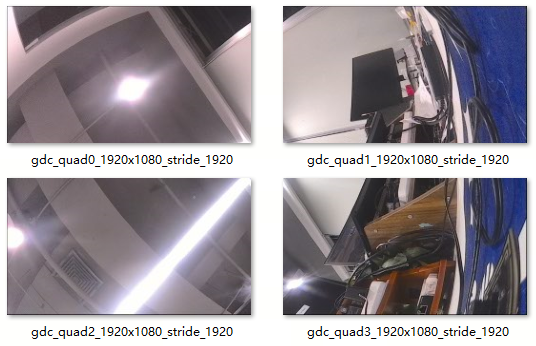
On the GDC side, the example uses AFFINE mode to pre-generate and load 4 sets of binbuf based on the input ROI (upper-left, upper-right, lower-left, lower-right quadrant configurations). During runtime, it dynamically switches binbuf and continuously captures 4 GDC output images saved to the current directory.
Software Architecture Description
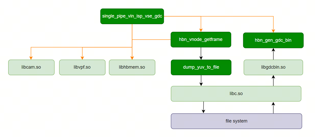
Data Flow Description
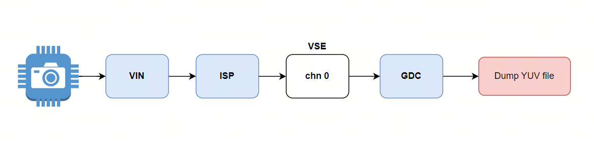
Code Location and Directory Structure
Code location:
app/samples/platform_samples/sample_pipeline/single_pipe_vin_isp_vse_gdcDirectory structure
single_pipe_vin_isp_vse_gdc
├── Makefile
├── single_pipe_vin_isp_vse_gdc
└── single_pipe_vin_isp_vse_gdc.c
API Flow Description
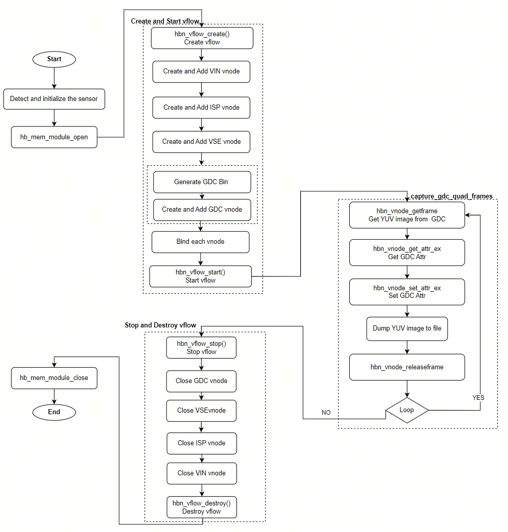
3.15.5.2. Build and Deployment
Build
Enter the
single_pipe_vin_isp_vse_gdcdirectory and runmaketo compileThe output binary is
single_pipe_vin_isp_vse_gdclocated in the source directoryFor detailed compilation instructions, refer to the Build Method section
Program Deployment
After uploading single_pipe_vin_isp_vse_gdc to the development board, run chmod +x single_pipe_vin_isp_vse_gdc to grant execution permission.
3.15.5.3. Run
How to Run the Program
Execute the program directly with ./single_pipe_vin_isp_vse_gdc to display help information
Program Parameter Options
Usage: ./single_pipe_vin_isp_vse_gdc [OPTIONS]
Options:
  -s <sensor_index>             Specify sensor index
  -c <channel_type>             Specify channel type: vo and vf and io and if, default: vf:if
                Support both individual configuration and combined configuration.
                The individual configuration supports four types:
                                1. vo: vin online isp
                                2. vf: vin offline isp
                                3. io: isp online vse
                                4. if: isp offline vse
                The combination configuration supports four types:
                                1. vo:io  vin online isp + isp online vse
                                2. vo:if  vin online isp + isp offline vse
                                3. vf:io  vin offline isp + isp online vse
                                4. vf:if  vin offline isp + isp offline vse
  -h    Show help message
Parameter descriptions
-s: Specify the Camera Sensor model and configuration-c: Specify the connection mode forVIN->ISPandISP->VSE(online/offline)-h: Print help information
Running Results
After running this example, 4 sets of GDC binbuf configurations will be switched sequentially, and 4 output images will be saved with file names as follows:
gdc_quad0_1920x1080_stride_1920.yuv
gdc_quad1_1920x1080_stride_1920.yuv
gdc_quad2_1920x1080_stride_1920.yuv
gdc_quad3_1920x1080_stride_1920.yuv
This section uses sc230ai as an example to demonstrate the usage of single_pipe_vin_isp_vse_gdc
Run the following command:
./single_pipe_vin_isp_vse_gdc -s 3 -c vf:if
Image output is as follows:
Notes
Multiple different binbufs will occupy multiple ION memory blocks. Identical binbufs will share the same ION memory block.
3.15.6. multi_pipe_vin_isp_vse
3.15.6.1. Function Overview
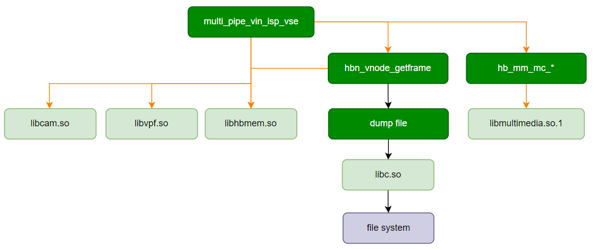
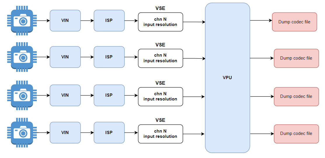
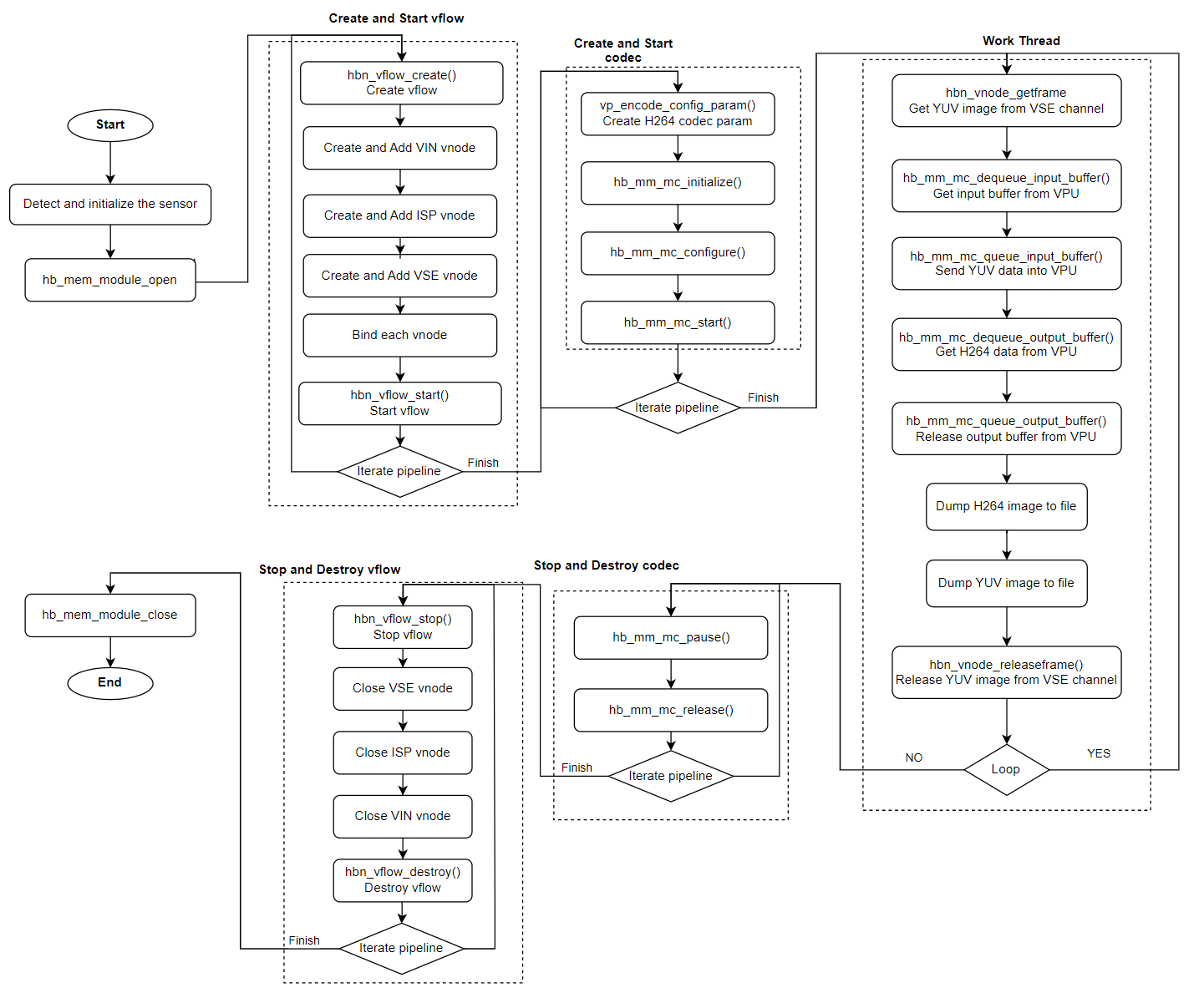
multi_pipe_vin_isp_vse is a test program for multiple video pipelines, completing hardware initialization and pipeline integration for modules including MIPI CSI, VIN, ISP, VSE, and CODEC, and acquiring h264 encoded data from CODEC. Users can refer to this program to learn how to use the HBN API to create multiple video vflow pipelines.
Software Architecture Description
Data Flow Description
Code Location and Directory Structure
Code location:
app/samples/platform_samples/sample_pipeline/multi_pipe_vin_isp_vseDirectory structure
multi_pipe_vin_isp_vse
├── Makefile
├── multi_pipe_vin_isp_vse
└── multi_pipe_vin_isp_vse.c
API Flow Description
3.15.6.2. Build and Deployment
Build
Enter the
multi_pipe_vin_isp_vsedirectory and runmaketo compile.The output binary is
multi_pipe_vin_isp_vselocated in the source directory.For detailed build instructions, refer to the Build Method section.
Program Deployment
After uploading multi_pipe_vin_isp_vse to the development board, run chmod +x multi_pipe_vin_isp_vse to grant execution permissions.
3.15.6.3. Run
How to Run the Program
Running ./multi_pipe_vin_isp_vse -h directly displays the help message.
Program Option Descriptions
Options:
-c, --config="sensor=id channel=vse_chn type=TYPE output=FILE"
                Configure parameters for each video pipeline, can be repeated up to 4 times.
                sensor   --  Sensor index, can have multiple parameters, reference sensor list.
                mode     --  Sensor mode of camera_config_t
                channel  --  Vse channel index bind to encode, default 0, can be set to [0-5].
                type     --  Encode type, default is h264, can be set to [h264, h265].
                output   --  Save codec stream data to file, default is 'pipeline[xx]_[width]x[height]_[xxx]fps.[type]'.
-v, --verbose   Enable verbose mode
-h, --help      Show help message
-c, --config="sensor=id channel=vse_chn type=TYPE output=FILE"Configures parameters for each video pipeline. This option can be repeated up to 4 times to configure up to 4 video pipelines.
sensoris required;channel,type, andoutputare optional. Default values are used if not specified.sensor: Sensor index (required).channel: VSE channel index (optional, default 0, range [0-5]).type: Encoding type (optional, default h264, supports [h264, h265]).output: File to save encoded stream data (optional, default format:pipeline[xx]_[width]x[height]_[xxx]fps.[type]).
-v, --verboseEnables verbose mode.
-h, --helpDisplays help message.
Note: To adjust the number of video pipelines, simply increase or decrease the number of -c parameter sets. Up to 4 video pipelines are supported.
Runtime Behavior
This section demonstrates the use of multi_pipe_vin_isp_vse with two video pipelines.
Run the following command:
./multi_pipe_vin_isp_vse -c "sensor=2 channel=0 type=h264 output=output0.h264" -c "sensor=8 channel=1 type=h265 output=output1.h265" -v
Pipeline configuration details:
Pipeline 0:
sensor=2 channel=0 type=h264 output=output0.h264Sensor name:
sc230ai-10fpsVSE channel: 0
Encoding type: h264
Output file: output0.h264
Pipeline 1:
sensor=8 channel=1 type=h265 output=output1.h265Sensor name:
imx415-30fps-2laneVSE channel: 1
Encoding type: h265
Output file: output1.h265
Example log output:
# ./multi_pipe_vin_isp_vse -c "sensor=2 channel=0 type=h264 output=output0.h264" -c "sensor=8 channel=1 type=h265 output=output1.h265" -v
Using index:2  sensor_name:sc230ai-10fps  config_file:linear_1920x1080_raw10_10fps_1lane.c
[INFO] board_id is 0x0202, not need skip sci1.
mipi mclk is configed.
Searching camera sensor on device: /proc/device-tree/soc/cam/vcon@0 i2c bus: 4 mipi rx phy: 0
INFO: Found sensor_name:sc230ai-10fps on mipi rx csi 0, i2c addr 0x30, config_file:linear_1920x1080_raw10_10fps_1lane.c
Using index:8  sensor_name:imx415-30fps-2lane  config_file:linear_3840x2160_raw10_30fps_2lane.c
[INFO] board_id is 0x0202, not need skip sci1.
mipi mclk is not configed.
Searching camera sensor on device: /proc/device-tree/soc/cam/vcon@1 i2c bus: 1 mipi rx phy: 1
WARN: Sensor Name: imx415-30fps-2lane, Expected Chip ID: 0x03, Actual Chip ID Read: 0x00
mipi mclk is configed.
Searching camera sensor on device: /proc/device-tree/soc/cam/vcon@2 i2c bus: 2 mipi rx phy: 2
WARN: Sensor Name: imx415-30fps-2lane, Expected Chip ID: 0x03, Actual Chip ID Read: 0x00
mipi mclk is configed.
Searching camera sensor on device: /proc/device-tree/soc/cam/vcon@3 i2c bus: 7 mipi rx phy: 3
INFO: Found sensor_name:imx415-30fps-2lane on mipi rx csi 3, i2c addr 0x1a, config_file:linear_3840x2160_raw10_30fps_2lane.c
Pipeline index 0:
        Sensor index: 2
        Sensor name: sc230ai-10fps
        Active mipi host: 0
        Vse Channel: 0
        Encode type: h264
        Output file: output0.h264
Pipeline index 1:
        Sensor index: 8
        Sensor name: imx415-30fps-2lane
        Active mipi host: 3
        Vse Channel: 1
        Encode type: h265
        Output file: output1.h265
MIPI host: 0x9
  Host 0: Used
  Host 3: Used
Verbose: 1
hbn_vnode_set_ochn_attr: 1920x1080
Create Encode idx: 0, init successful
Input width 3840 exceeds maximum width 1920 for channel 1. Adjusting to maximum width.
Input height 2160 exceeds maximum height 1080 for channel 1. Adjusting to maximum height.
hbn_vnode_set_ochn_attr: 1920x1080
Create Encode idx: 1, init successful
Encodec idx: 0 type:0 get stream size:306122
Encodec idx: 0 type:0 get stream size:150586
Encodec idx: 1 type:1 get stream size:8447
Encodec idx: 1 type:1 get stream size:10329
Encodec idx: 0 type:0 get stream size:154342
Encodec idx: 1 type:1 get stream size:10957
Encodec idx: 1 type:1 get stream size:10894
Encodec idx: 1 type:1 get stream size:7949
Encodec idx: 0 type:0 get stream size:111222
Encodec idx: 1 type:1 get stream size:7741
Encodec idx: 1 type:1 get stream size:9076
Encodec idx: 1 type:1 get stream size:8035
Encodec idx: 0 type:0 get stream size:132560
After running, the following encoded video files will be saved:
output0.h264 output1.h265
3.15.7. multi_pipe_gdc_stitching
3.15.7.1. Function Overview
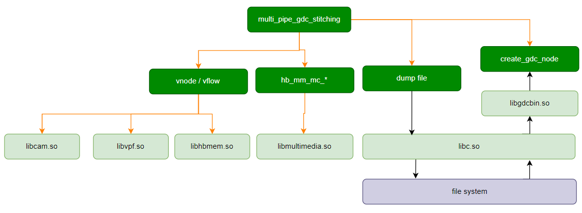
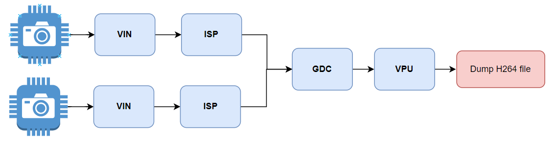
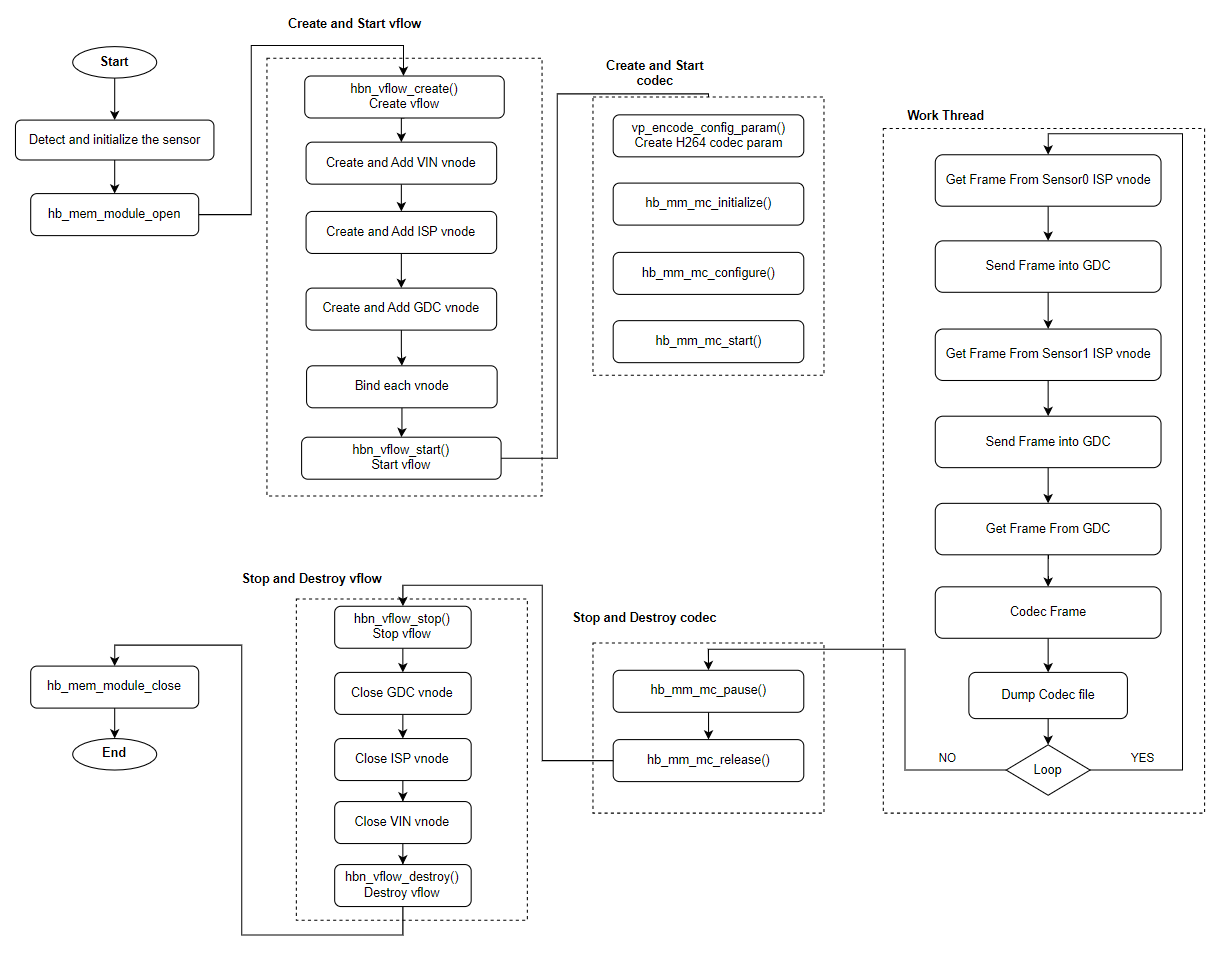
The multi_pipe_gdc_stitching program acquires images from two sensors with identical resolution, performs GDC stitching, and encodes the stitched output into an h264 video.
Software Architecture Description
Data Flow Description
Code Location and Directory Structure
Code location:
app/samples/platform_samples/sample_pipeline/multi_pipe_gdc_stitchingDirectory structure
multi_pipe_gdc_stitching
├── Makefile
├── multi_pipe_gdc_stitching
└── multi_pipe_gdc_stitching.c
API Flow Description
3.15.7.2. Build and Deployment
Build
Enter the
multi_pipe_gdc_stitchingdirectory and runmaketo compile.The output binary is
multi_pipe_gdc_stitchinglocated in the source directory.For detailed build instructions, refer to the Build Method section.
Program Deployment
After uploading multi_pipe_gdc_stitching to the development board, run chmod +x multi_pipe_gdc_stitching to grant execution permissions.
3.15.7.3. Run
How to Run the Program
Running ./multi_pipe_gdc_stitching directly displays the help message.
Program Option Descriptions
Usage: multi_pipe_gdc_stitching [Options]
Options:
-c, --config="sensor=id"
                Configure parameters for each video pipeline, can be repeated up to 2 times.
                sensor   --  Sensor index, can have multiple parameters, reference sensor list.
-v, --verbose   Enable verbose mode
-h, --help      Show help message
-c, --config="sensor=id"Configures parameters for each video pipeline. Currently supports up to 2 camera configurations.
-v, --verboseEnables verbose mode.
-h, --helpDisplays help message.
Note: Two cameras with the same resolution must be configured.
Runtime Behavior
Example log output:
# ./multi_pipe_gdc_stitching -c "sensor=3" -c "sensor=3"
Using index:3  sensor_name:sc230ai-30fps  config_file:linear_1920x1080_raw10_30fps_1lane.c
[INFO] board_id is 0x0202, not need skip sci1.
mipi mclk is configed.
Searching camera sensor on device: /proc/device-tree/soc/cam/vcon@0 i2c bus: 4 mipi rx phy: 0
INFO: Found sensor_name:sc230ai-30fps on mipi rx csi 0, i2c addr 0x30, config_file:linear_1920x1080_raw10_30fps_1lane.c
Using index:3  sensor_name:sc230ai-30fps  config_file:linear_1920x1080_raw10_30fps_1lane.c
[INFO] board_id is 0x0202, not need skip sci1.
mipi mclk is not configed.
Searching camera sensor on device: /proc/device-tree/soc/cam/vcon@1 i2c bus: 1 mipi rx phy: 1
WARN: Sensor Name: sc230ai-30fps, Expected Chip ID: 0xCB34, Actual Chip ID Read: 0x00
mipi mclk is configed.
Searching camera sensor on device: /proc/device-tree/soc/cam/vcon@2 i2c bus: 2 mipi rx phy: 2
WARN: Sensor Name: sc230ai-30fps, Expected Chip ID: 0xCB34, Actual Chip ID Read: 0x00
mipi mclk is configed.
Searching camera sensor on device: /proc/device-tree/soc/cam/vcon@3 i2c bus: 7 mipi rx phy: 3
INFO: Found sensor_name:sc230ai-30fps on mipi rx csi 3, i2c addr 0x30, config_file:linear_1920x1080_raw10_30fps_1lane.c
total_pipeline_num:2
Pipeline index 0:
        Sensor index: 3
        Sensor name: sc230ai-30fps
        Active mipi host: 0
Pipeline index 1:
        Sensor index: 3
        Sensor name: sc230ai-30fps
        Active mipi host: 3
Encode type: h264
Output file: pipeline1_1920x1080_30fps.h264
MIPI host: 0x9
  Host 0: Used
Verbose: 0
Create Encode idx: 0, init successful
q
^C[  145.555162] [VPF ops]:[L153][S2][gdc0] vpf_safety_close: sudden close
[  145.561818] vin sensor1: sensor_frame_end_stop_wait 488 fe 0ms abort
[  145.569080] [VPF ops]:[L153][S1][vin3] vpf_safety_close: sudden close
[  145.577640] [VPF ops]:[L153][S1][isp0] vpf_safety_close: sudden close
[  145.589144] vin sensor0: sensor_frame_end_stop_wait 509 fe 0ms abort
[  145.596381] [VPF ops]:[L153][S0][vin0] vpf_safety_close: sudden close
[  145.604412] [VPF ops]:[L153][S0][isp0] vpf_safety_close: sudden close
...
After running, the following encoded video file will be saved:
pipeline1_1920x1080_30fps.h264
3.15.8. multi_pipe_vin_isp_vse_gpu2d
3.15.8.1. Function Overview
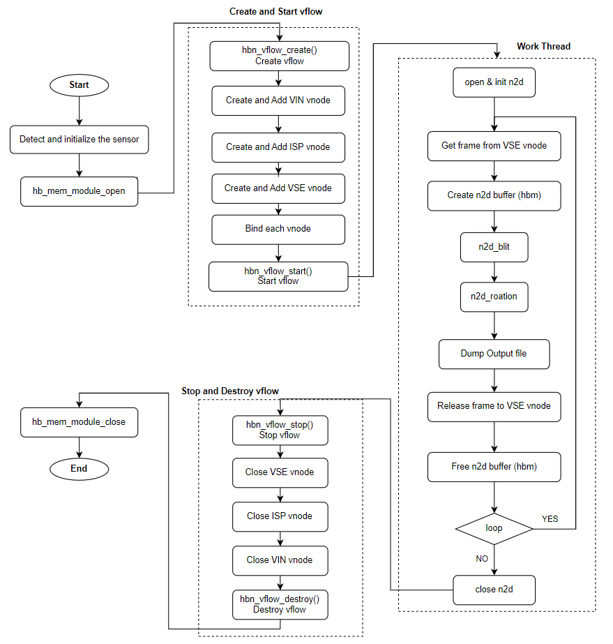
multi_pipe_vin_isp_vse_gpu2d is a test program for multiple video pipelines, completing hardware initialization and pipeline integration for MIPI CSI, VIN, ISP, VSE, and GPU2D modules. The program processes data through the SIF->ISP->VSE pipeline, applies GPU2D rotation, and saves the rotated images as BMP format files in the current directory.
Software Architecture Description
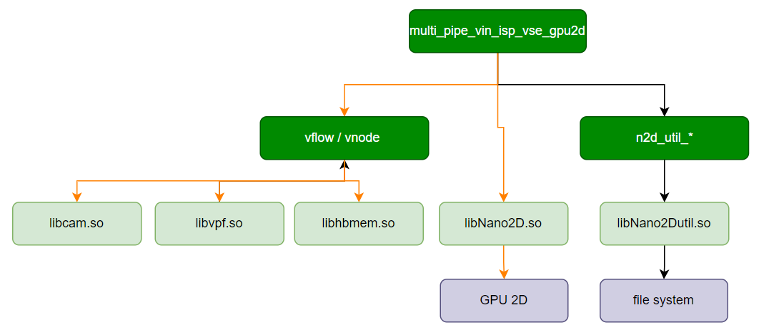
Data Flow Description
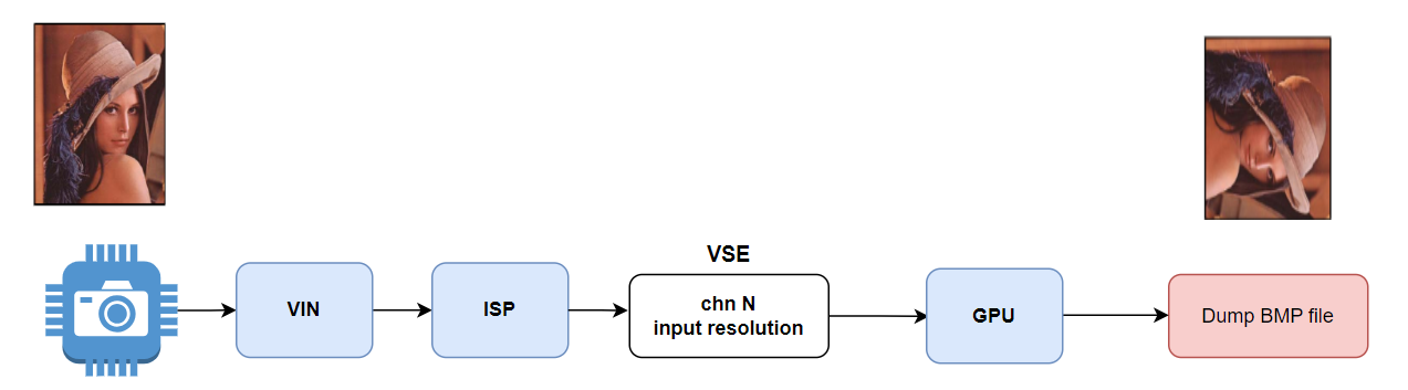
Code Location and Directory Structure
Code location:
app/samples/platform_samples/sample_pipeline/multi_pipe_vin_isp_vse_gpu2dDirectory structure
multi_pipe_vin_isp_vse_gpu2d
├── Makefile
├── create_n2d_buffer_wraper.c
├── create_n2d_buffer_wraper.h
├── multi_pipe_vin_isp_vse_gpu2d
└── multi_pipe_vin_isp_vse_gpu2d.c
API Flow Description
3.15.8.2. Build and Deployment
Build
Enter the
multi_pipe_vin_isp_vse_gpu2ddirectory and runmaketo compile.The output binary is
multi_pipe_vin_isp_vse_gpu2dlocated in the source directory.For detailed build instructions, refer to the Build Method section.
Program Deployment
After uploading multi_pipe_vin_isp_vse_gpu2d to the development board, run chmod +x multi_pipe_vin_isp_vse_gpu2d to grant execution permissions.
3.15.8.3. Run
How to Run the Program
Running ./multi_pipe_vin_isp_vse_gpu2d directly displays the help message.
Program Option Descriptions
Usage: multi_pipe_vin_isp_vse_gpu2d [Options]
Options:
-c, --config="sensor=id output=FILE"
                Configure parameters for each video pipeline, can be repeated up to 4 times.
                sensor   --  Sensor index, can have multiple parameters, reference sensor list.
                output   --  Save bmp data to file.
-v, --verbose   Enable verbose mode
-y, --enable yuv-debug
-h, --help      Show help message
-c, --config="sensor=id channel=vse_chn output=FILE"Configure parameters for each video pipeline, can be repeated up to 4 times to set up to 4 video pipelines.
sensor (required): Sensor index, can have multiple parameters, refer to sensor list.output (optional): Save encoded stream data to file. Default naming format is ‘output_sensor’id_[width]x[height]_rotated_count.[bmp]`.
-v, --verboseEnable verbose mode.
-h, --helpShow help message.
Running Effect
This example uses two sc230ai sensors to demonstrate how to use multi_pipe_vin_isp_vse_gpu2d.
Run the following command:
./multi_pipe_vin_isp_vse_gpu2d -c "sensor=3" -c "sensor=3"
Sample log output:
root@buildroot:/app/platform_samples/sample_pipeline/multi_pipe_vin_isp_vse_gpu2d# ./multi_pipe_vin_isp_vse_gpu2d -c "sensor=3" -c "sensor=3"
Using index:3  sensor_name:sc230ai-30fps  config_file:linear_1920x1080_raw10_30fps_1lane.c
[INFO] board_id is 0x0202, not need skip sci1.
mipi mclk is configed.
Searching camera sensor on device: /proc/device-tree/soc/cam/vcon@0 i2c bus: 4 mipi rx phy: 0
INFO: Found sensor_name:sc230ai-30fps on mipi rx csi 0, i2c addr 0x30, config_file:linear_1920x1080_raw10_30fps_1lane.c
Using index:3  sensor_name:sc230ai-30fps  config_file:linear_1920x1080_raw10_30fps_1lane.c
[INFO] board_id is 0x0202, not need skip sci1.
mipi mclk is not configed.
Searching camera sensor on device: /proc/device-tree/soc/cam/vcon@1 i2c bus: 1 mipi rx phy: 1
WARN: Sensor Name: sc230ai-30fps, Expected Chip ID: 0xCB34, Actual Chip ID Read: 0x00
WARN: Sensor Name: sc230ai-30fps, Expected Chip ID: 0xCB34, Actual Chip ID Read: 0x00
WARN: Sensor Name: sc230ai-30fps, Expected Chip ID: 0xCB34, Actual Chip ID Read: 0x00
WARN: Sensor Name: sc230ai-30fps, Expected Chip ID: 0xCB34, Actual Chip ID Read: 0x00
mipi mclk is configed.
Searching camera sensor on device: /proc/device-tree/soc/cam/vcon@2 i2c bus: 2 mipi rx phy: 2
INFO: Found sensor_name:sc230ai-30fps on mipi rx csi 2, i2c addr 0x30, config_file:linear_1920x1080_raw10_30fps_1lane.c
total_pipeline_num:2
Pipeline index 0:
        Sensor index: 3
        Sensor name: sc230ai-30fps
        Active mipi host: 0
        Vse Channel: 0
        Encode type: bmp
        Output file:
Pipeline index 1:
        Sensor index: 3
        Sensor name: sc230ai-30fps
        Active mipi host: 2
        Vse Channel: 0
        Encode type: bmp
        Output file:
MIPI host: 0x5
  Host 0: Used
  Host 2: Used
Verbose: 0
mipi rx = 0,active_mipi_host = 0
isp_width:1920 , isp_height:1080hbn_vnode_set_ochn_attr: 1920x1080
mipi rx = 2,active_mipi_host = 2
isp_width:1920 , isp_height:1080hbn_vnode_set_ochn_attr: 1920x1080
************ n2d read start*********
Saved file to [./_width:1920_height:1080_stride1920_frameid20.bmp].
Saved file to [./_width:1920_height:1080_stride1920_frameid5.bmp].
Saved file to [./_width:1920_height:1080_stride1920_frameid32.bmp].
Saved file to [./_width:1920_height:1080_stride1920_frameid16.bmp].
Saved file to [./_width:1920_height:1080_stride1920_frameid43.bmp].
Saved file to [./_width:1920_height:1080_stride1920_frameid27.bmp].
Saved file to [./_width:1920_height:1080_stride1920_frameid55.bmp].
Saved file to [./_width:1920_height:1080_stride1920_frameid39.bmp].
Saved file to [./_width:1920_height:1080_stride1920_frameid70.bmp].
Saved file to [./_width:1920_height:1080_stride1920_frameid53.bmp].
Saved file to [./_width:1920_height:1080_stride1920_frameid78.bmp].
Saved file to [./_width:1920_height:1080_stride1920_frameid59.bmp].
Saved file to [./_width:1920_height:1080_stride1920_frameid85.bmp].
Saved file to [./_width:1920_height:1080_stride1920_frameid66.bmp].
Saved file to [./_width:1920_height:1080_stride1920_frameid92.bmp].
Saved file to [./_width:1920_height:1080_stride1920_frameid93.bmp].
Saved file to [./_width:1920_height:1080_stride1920_frameid118.bmp].
Saved file to [./_width:1920_height:1080_stride1920_frameid99.bmp].
Saved file to [./_width:1920_height:1080_stride1920_frameid125.bmp].
Saved file to [./_width:1920_height:1080_stride1920_frameid106.bmp].
Saved file to [./_width:1920_height:1080_stride1920_frameid132.bmp].
Saved file to [./_width:1920_height:1080_stride1920_frameid113.bmp].
Saved file to [./_width:1920_height:1080_stride1920_frameid139.bmp].
Saved file to [./_width:1920_height:1080_stride1920_frameid120.bmp].
Saved file to [./_width:1920_height:1080_stride1920_frameid146.bmp].
Saved file to [./_width:1920_height:1080_stride1920_frameid127.bmp].
Saved file to [./_width:1920_height:1080_stride1920_frameid153.bmp].
Saved file to [./_width:1920_height:1080_stride1920_frameid134.bmp].
Saved file to [./_width:1920_height:1080_stride1920_frameid160.bmp].
Saved file to [./_width:1920_height:1080_stride1920_frameid141.bmp].
Saved file to [./_width:1920_height:1080_stride1920_frameid167.bmp].
Saved file to [./_width:1920_height:1080_stride1920_frameid148.bmp].
encode thread end
After running, the following encoded files will be saved:
_width:1920_height:1080_stride1920_frameid160.bmp
_width:1920_height:1080_stride1920_frameid167.bmp
3.15.9. multi_pipe_crop_and_stitch
3.15.9.1. Function Overview
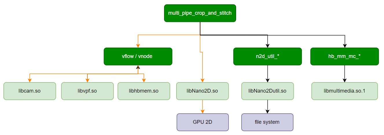
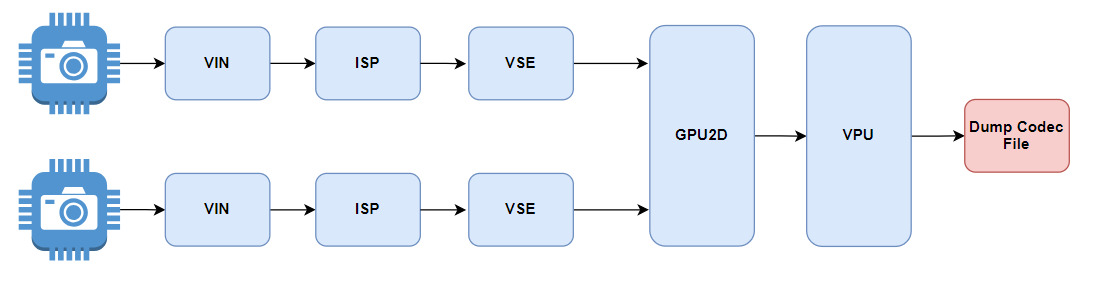
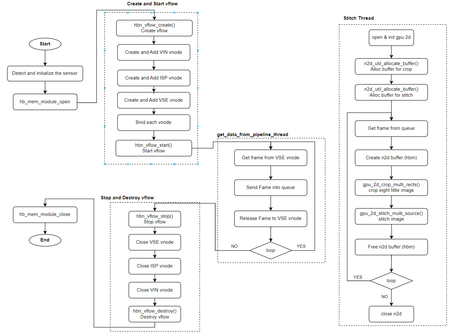
multi_pipe_crop_and_stitch is a test program for multiple video pipelines, which completes hardware initialization and pipeline connection for modules including MIPI CSI, VIN, ISP, VSE, 2D GPU, and CODEC. Users can refer to this program to learn how to use the HBN API to create multiple video vflow pipelines and use the 2D GPU to achieve image cropping, scaling, and stitching.
Key steps are as follows:
Two video streams are captured simultaneously and scaled to 4K via VSE.
Extract 640×480 images from the top-left, top-right, bottom-left, and bottom-right corners of each video stream, resulting in 8 small images.
Scale up the 8 small images obtained in step 2.
Stitch the two original video frames and the 8 small images into a single 4K image.
Encode the stitched image using H265 and save it to the file
output.h265.
Note: Currently supported camera resolutions are: 1920×1080 and 3840×2160.
Software Architecture
Data Flow
Code Location and Directory Structure
Code location:
app/samples/platform_samples/sample_pipeline/multi_pipe_crop_and_stitchDirectory structure:
multi_pipe_crop_and_stitch
├── Makefile
├── bpu_limit.sh
├── multi_pipe_crop_and_stitch
├── multi_pipe_crop_and_stitch.c
├── param_parser.c
├── param_parser.h
├── qos.sh
├── qos_read.sh
├── run_gdc_yolo_h264_mjpeg.sh
├── run_gdc_yolo_h265.sh
├── run_gdc_yolo_hdmi.sh
└── run_noqos.sh
API Flow
3.15.9.2. Build and Deployment
Build
Enter the
multi_pipe_crop_and_stitchdirectory and runmaketo compile.The output binary is
multi_pipe_crop_and_stitchin the source directory.For detailed build instructions, see the Build Method section.
Program Deployment
After uploading multi_pipe_crop_and_stitch to the development board, run chmod +x multi_pipe_crop_and_stitch to make it executable.
3.15.9.3. Run
Running the Program
Run ./multi_pipe_crop_and_stitch directly to get help information.
Program Options
Usage: multi_pipe_crop_and_stitch [Options]
Options:
-c, --config="sensor=id "
                Configure parameters for each video pipeline, can be repeated up to 4 times.
                sensor   --  Sensor index,can have multiple parameters, reference sensor list.
                gdc      --  Enable gdc, default is disable.
                out264   --  Enable codec h264 stream, default is disable.
                outmjpeg --  Enable codec mjpeg stream, default is disable.
                file     --  Enable codec stream save as file, default is disable.
-o, --output="file or hdmi, default is nothing output
-r, --ratio="camera image width ratio, used to blend, default is 0.0
-b, --bpu_enable        Enable bpu, default is disable
-p, --bpu_postprocess_enable    Enable bpu postprocess, default is disable
-v, --verbose   Enable verbose mode
-h, --help      Show help message
-c, --config="sensor=id"Configure parameters for each video pipeline. Currently supports up to two cameras, with individual settings per sensor:
sensor: Sensor index, refer to sensor list.gdc: Enable GDC, default is 0, valid values [0-1].out264: Enable H264 encoding, default is 0, valid values [0-1].outmjpeg: Enable MJPEG encoding, default is 0, valid values [0-1].file: Save encoded streams to file, filename format:Chn[channel_number].[codec_type].
-o, --outputOutput method for the stitched image:
-o file: Output H265 encoded file namedoutput.h265.-o hdmi: Output to HDMI display (currently supports only 4K resolution).
-b, --bpu_enableEnable algorithm thread for human detection using YOLOv5.
-p, --bpu_postprocess_enableEnable algorithm post-processing.
-v, --verboseEnable verbose logging.
-h, --helpShow help message.
Running Effect
This example uses two sc230ai sensors to demonstrate how to use multi_pipe_crop_and_stitch to test image cropping, stitching, and output H265 encoded file.
Run the following test command:
./multi_pipe_crop_and_stitch -c "sensor=3" -c "sensor=3" -o file
Sample log output:
Using index:3  sensor_name:sc230ai-30fps  config_file:linear_1920x1080_raw10_30fps_1lane.c
[INFO] board_id is 202, not need skip sci1.
mipi mclk is configed.
Searching camera sensor on device: /proc/device-tree/soc/cam/vcon@0 i2c bus: 4 mipi rx phy: 0
mipi mclk is not configed.
Searching camera sensor on device: /proc/device-tree/soc/cam/vcon@1 i2c bus: 1 mipi rx phy: 1
mipi mclk is configed.
Searching camera sensor on device: /proc/device-tree/soc/cam/vcon@2 i2c bus: 2 mipi rx phy: 2
INFO: Found sensor_name:sc230ai-30fps on mipi rx csi 2, i2c addr 0x30, config_file:linear_1920x1080_raw10_30fps_1lane.c
mipi host 2
MIPI host: 0x4
  Host 2: Used

Using index:3  sensor_name:sc230ai-30fps  config_file:linear_1920x1080_raw10_30fps_1lane.c
[INFO] board_id is 202, not need skip sci1.
mipi mclk is configed.
Searching camera sensor on device: /proc/device-tree/soc/cam/vcon@0 i2c bus: 4 mipi rx phy: 0
mipi mclk is not configed.
Searching camera sensor on device: /proc/device-tree/soc/cam/vcon@1 i2c bus: 1 mipi rx phy: 1
mipi mclk is configed.
Searching camera sensor on device: /proc/device-tree/soc/cam/vcon@3 i2c bus: 7 mipi rx phy: 3
INFO: Found sensor_name:sc230ai-30fps on mipi rx csi 3, i2c addr 0x30, config_file:linear_1920x1080_raw10_30fps_1lane.c
mipi host 3
MIPI host: 0xc
  Host 2: Used
  Host 3: Used

 Show sensor info:
  Pipeline index 0:
        Sensor index: 3
        Sensor name: sc230ai-30fps
        Active mipi host: 2
        Vse Channel: 5
  Pipeline index 1:
        Sensor index: 3
        Sensor name: sc230ai-30fps
        Active mipi host: 3
        Vse Channel: 5
hbn_vnode_set_ochn_attr: 3840x2160 fps:30
hbn_vnode_set_ochn_attr: 3840x2160 fps:30

Codec param:
        codec type :H265
        codec fps :30
        codec width :3840
        codec height :2160
Create Encode idx: 0, init successful

input q to stop :
During execution, the following encoded video file will be saved:
output.h264
3.15.10. uvc_gadget_camera
3.15.10.1. Function Overview
uvc_gadget_camera provides the following functions:
Capture data from MIPI camera through CSI, VIN, ISP, VSE, CODEC, and send it to PC via USB Gadget for display. Currently supports only H264 format.
UAC1 plays PCM file in a loop, using default 48K sample rate, dual channel, 16-bit.
UAC1 records PCM file, using default 48K sample rate, dual channel, 16-bit.
Software Architecture
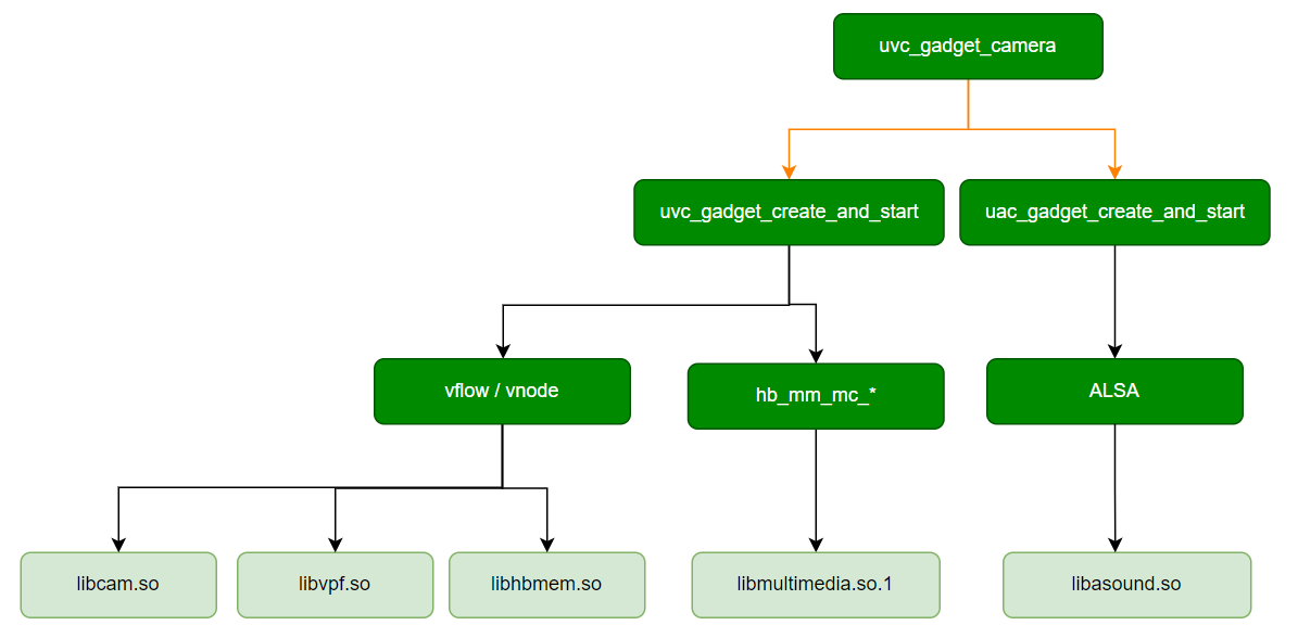
Data Flow
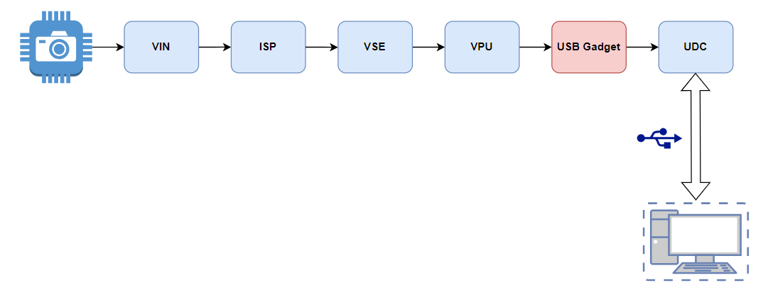
Code Location and Directory Structure
Code location:
app/samples/platform_samples/sample_pipeline/uvc_gadget_cameraDirectory structure:
.
├── Makefile
├── alsa_device.c
├── audio
│   └── count10_48K_chn2_s16le.pcm
├── include
│   ├── alsa_device.h
│   ├── uac_common.h
│   ├── uac_gadget.h
│   ├── uac_micphone.h
│   ├── uac_speaker.h
│   ├── utils.h
│   ├── uvc.h
│   ├── uvc_gadget.h
│   └── uvc_gadget_api.h
├── lib
│   └── libguvc.a
├── mqueue.c
├── mqueue.h
├── uac_gadget.c
├── uac_micphone.c
├── uac_speaker.c
├── uvc_gadget_camera
├── uvc_gadget_camera.c
├── uvc_gadget_wraper.c
├── uvc_gadget_wraper.h
├── vp_codec.c
├── vp_codec.h
├── vp_pipeline.h
└── vp_pipeline.c
API Flow
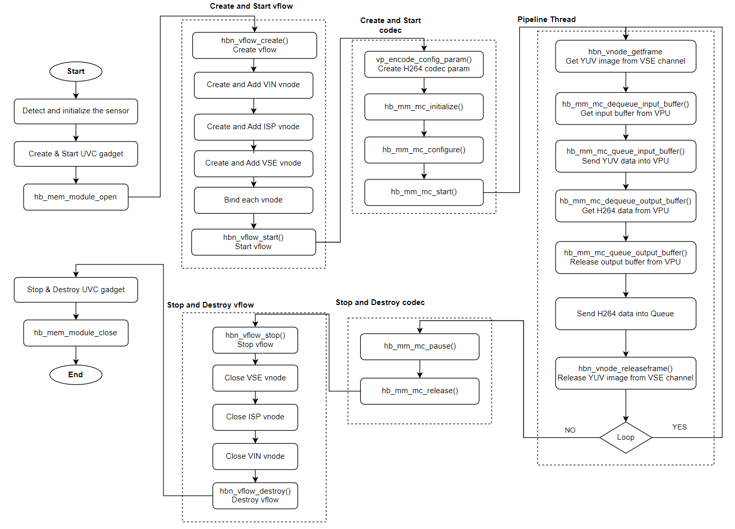
3.15.10.2. Build and Deployment
Build
Enter the
uvc_gadget_cameradirectory and runmaketo compile.The output binary is
uvc_gadget_camerain the source directory.For detailed build instructions, see the Build Method section.
Program Deployment
After uploading uvc_gadget_camera to the development board, run chmod +x uvc_gadget_camera to make it executable.
3.15.10.3. Run
Running the Program
Run ./uvc_gadget_camera directly to get help information.
Program Options
Usage: get_isp_data [OPTIONS]
Options:
  -s <sensor_index>      Specify sensor index
  -m <sensor_mode>       Specify sensor mode of camera_config_t
  -p <play PCM file>     Specifies the audio playback file path
  -r <record PCM file>   Specify the audio recording file path
  -h                     Show this help message
-s <sensor_index>Specify the
Camera Sensorindex.Example:
-s 0means using sensor with index 0.
-m <sensor_mode>Specify the sensor mode (sensor_mode) in
camera_config_t.Example:
-m 6means using mode 6 (Slave). This option is not supported by all sensors; use according to the specificCamera Sensormodule design.
-p <play PCM file>Specify the path of the PCM file to play.
Example:
-p /userdata/play.pcm, using default 48K sample rate, dual channel, 16-bit.
-r <record PCM file>Specify the path to save the recorded PCM file.
Example:
-r /userdata/rec.pcm, using default 48K sample rate, dual channel, 16-bit.
-hShow help message. Running this command will display detailed descriptions of the above options.
Running Effect
Example 1: Testing UVC
Connect the development board and PC using a USB data cable, refer to USB 2.0 Interface.
By default, the USB interface is used for ADB. Run the following commands to switch to UVC gadget mode:
/etc/init.d/usb-gadget.sh stop
/etc/init.d/usb-gadget.sh start uvc isoc
The appearance of device node
/dev/video0indicates successful switch:
root@buildroot:~# ls /dev/video0
/dev/video0
Start
uvc_gadget_camera
Using sc230ai as an example, run the following command:
./uvc_gadget_camera -s 3
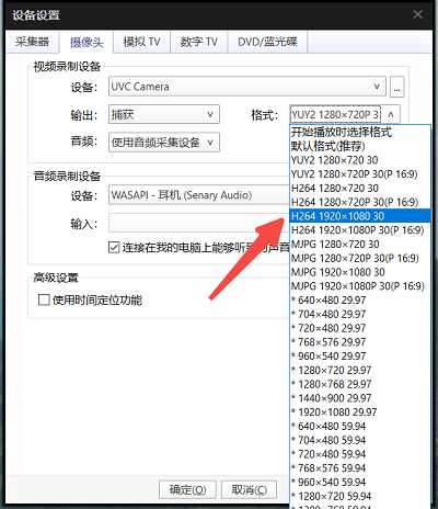
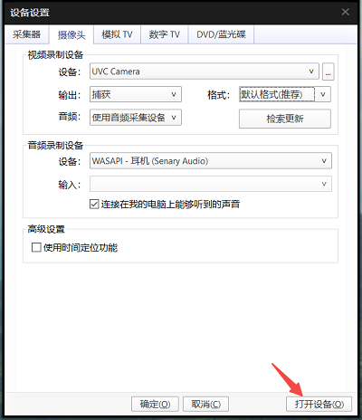
On the PC, open a USB Camera player such as PotPlayer. Press
Alt+Dto open camera settings, select “UVC Camera”, and click “Refresh”.
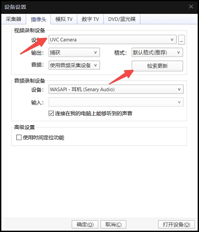
On the PC, select the appropriate configuration based on the camera’s resolution and frame rate, then open the camera.
Notes
After
usb-gadget.shscript starts UVC, the UVC peripheral does not appear immediately on PC. It is created only after running theuvc_gadget_cameraprogram.When opening the camera in PotPlayer on PC, if format options are not available, click “Refresh”.
When opening the camera in PotPlayer, ensure the format matches the actual camera parameters. Mismatched resolution or format will cause
uvc_gadget_camerato exit.
Example 2: Testing UVC + UAC1
/etc/init.d/usb-gadget.sh stop
/etc/init.d/usb-gadget.sh start uvc-uac1 isoc
Start
uvc_gadget_camera
Using sc230ai as example, play count10_48K_chn2_s16le.pcm in loop and record audio to /userdata/rec.pcm. Use the following command:
cd /app/platform_samples/sample_pipeline/uvc_gadget_camera/
./uvc_gadget_camera -s 3 -p count10_48K_chn2_s16le.pcm -r /userdata/rec.pcm
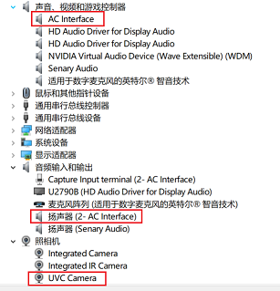
On the PC, Device Manager will show new UVC and UAC devices.
Running Results
Run command
./uvc_gadget_camera -s 3, log output as follows (uvc_gadget_camerawaits for PC client connection):
 ./uvc_gadget_camera -s 3
index:3 settle=-1 sensor_mode=0
Using index:3  sensor_name:sc230ai-30fps  config_file:linear_1920x1080_raw10_30fps_1lane.c
[INFO] board_id is 202, not need skip sci1.
mipi mclk is configed.
Searching camera sensor on device: /proc/device-tree/soc/cam/vcon@0 i2c bus: 4 mipi rx phy: 0
INFO: Found sensor_name:sc230ai-30fps on mipi rx csi 0, i2c addr 0x30, config_file:linear_1920x1080_raw10_30fps_1lane.c
##function uvc_gadget_init in
using uvc device: /dev/video0
###uvc_gadget_init###
using uvc device: /dev/video0
width: 1920
height: 1080
format: 1
io_method: 0
bulk_mode: 0
nbufs: 2
mult: 2
burst: 0
speed: 3
mult_alts: 0
h264_quirk: 0
maxpkt_quirk: 3072
uvc device is dwc3-gadget on bus gadget.0
uvc open succeeded, file descriptor = 4
uvc_size=3, maxpkt_size=3072
##function uvc_gadget_init succeed
##function uvc_gadget_start in
##function uvc_gadget_start succeed
'q' for exit
##function uvc_loop in
When PC initiates connection and correct format is provided, the following log appears:
STREAM ON! show video info:
==============================================
fcc: h264(0x34363248)
run_standalone: 1
uvc_devname: /dev/video0
mem: 0xffff9003b2a0
dummy_buf: (nil)
nbufs: 2
width: 1920
height: 1080
bulk: 0
imgsize: 0
imgdata: (nil)
maxpkt: 1024
speed: 3
mult_alts: 0
h264_quirk: 0
maxpkt_quirk: 3072
==============================================
3.15.11. sample_custom_capbuf
3.15.11.1. Function Overview
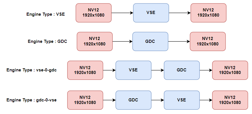
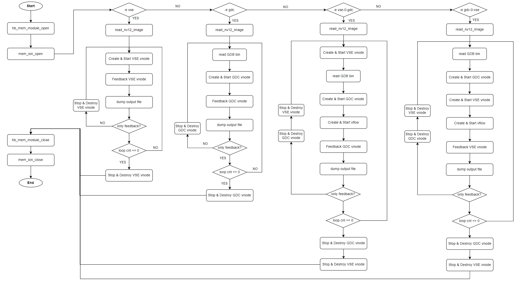
sample_custom_capbuf supports various VSE/GDC pipeline configurations via parameter options. Users can adjust parameters according to actual needs to build pipelines and verify module processing latency.
Software Architecture Description
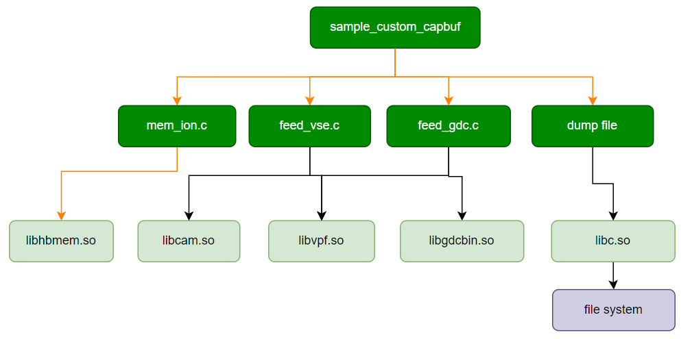
Data Flow Description
Code Location and Directory Structure
Code location:
app/samples/platform_samples/sample_pipeline/sample_custom_capbufDirectory structure
sample_custom_capbuf
├── Makefile
├── feedback_gdc.c
├── feedback_gdc.h
├── feedback_vse.c
├── feedback_vse.h
├── mem_ion.c
├── mem_ion.h
├── run_test.sh
├── sample_custom_capbuf
├── sample_custom_capbuf.c
├── test_res
│   ├── gdc.bin
│   └── test_image_1920x1080.yuv
├── vflow_connection.h
└── vflow_connection.c
API Flow Description
3.15.11.2. Compilation and Deployment
Compilation
Enter the
sample_custom_capbufdirectory and runmaketo compile.The output binary is
sample_custom_capbuflocated in the source directory.For detailed compilation methods, refer to the Build Instructions section.
Program Deployment
After uploading sample_custom_capbuf, run_test.sh, and the test_res directory to the development board, run the command chmod +x sample_custom_capbuf run_test.sh to grant executable permissions.
3.15.11.3. Execution
How to Run the Program
sample_custom_capbuf includes a pre-configured test script run_test.sh to validate processing latency of VSE/GDC modules under various scenarios. Users can modify run_test.sh as needed.
Simply execute the script via ./run_test.sh to run this test case.
Program Parameter Options
Usage: program -e <engine> [OPTIONS]
Options for vse:
-i, --input_file FILE   Specify the input file
-w, --input_width WIDTH Specify the input width
-h, --input_height HEIGHT       Specify the input height
-V, --verbose           Enable verbose mode
Options for gdc:
-c, --config_file FILE  Specify the config file
-i, --input_file FILE   Specify the input file
-o, --output_file FILE  Specify the output file
-w, --input_width WIDTH Specify the input width
-h, --input_height HEIGHT       Specify the input height
-x, --output_width WIDTH        Specify the output width
-y, --output_height HEIGHT      Specify the output height
Options for gdc-0-vse:
-i, --input_file FILE   Specify the input file
-w, --input_width WIDTH Specify the input width
-h, --input_height HEIGHT       Specify the input height
-V, --verbose           Enable verbose mode
-c, --config_file FILE  Specify the config file for gdc
-o, --output_file FILE  Specify the output file for gdc
-x, --output_width WIDTH        Specify the output width for gdc
-y, --output_height HEIGHT      Specify the output height for gdc
This test case uses the -e option to specify the module type to be tested. Supported module types are:
vse: scales an NV12 image using VSEgdc: performs distortion correction on an NV12 image using GDCvse-0-gdc: first scales via VSE channel 0, then applies GDC distortion correction, and outputs NV12gdc-0-vse: first applies GDC distortion correction, then scales via VSE channel 0, and outputs NV12
This sample uses environment variables defined in the run_test.sh script to control test options. The environment variables are described below:
CAP_LOOP_CNTSpecifies the number of test loops. If
CAP_LOOP_CNTis empty, only one test iteration is performed.
CAP_LOOP_FLAGSpecifies the vnode operation type. Supported values:
CAP_LOOP_ONLY_FEEDBACK: value 0, indicating that vnode is reused directly in each loop without destruction and recreationCAP_LOOP_FEEDBACK_AND_CREATE: value 1, indicating that vnode is recreated and reinitialized in each loop
CAP_BUF_FLAGSpecifies the output buffer type for feeding back to VSE/GDC:
CAP_BUF_CUSTOM: value 0, indicating buffer memory is allocated via HBM interface
CAP_BUF_CUSTOM_EXT: value 1, indicating buffer memory is allocated via ION interfaceCAP_BUF_INTERNAL: value 2, indicating buffer memory is obtained internally by the module
CAP_DUMP_FLAGIndicates whether to save output YUV images.
For VSE module, default output directory is
/userdata/vseFor GDC module, default output directory is
/userdata/gdc
CAP_THREAD_NUMSpecifies the number of threads created for concurrent module operations. If
CAP_THREAD_NUMis empty, only one test thread is created.
Notes
Only VSE, GDC, and GDC-bound-VSE feedback modes are supported.
For user-defined output buffers, the Y and UV address spaces must be contiguous, allocated from ION space, and must include valid bufferindex and share_id fields.
Execution Output
Run ./run_test.sh
...
==== feedback_thread_vse buf flag CAP_BUF_CUSTOM loop 100 time cost 1263.837 ms
==== feedback_thread_gdc buf flag CAP_BUF_CUSTOM loop 100 time cost 895.005 ms
==== feedback_thread_vse buf flag CAP_BUF_INTERNAL loop 100 time cost 1640.084 ms
==== feedback_thread_gdc buf flag CAP_BUF_INTERNAL loop 100 time cost 966.076 ms
...
3.15.12. uvc_capture_sample
3.15.12.1. Function Overview
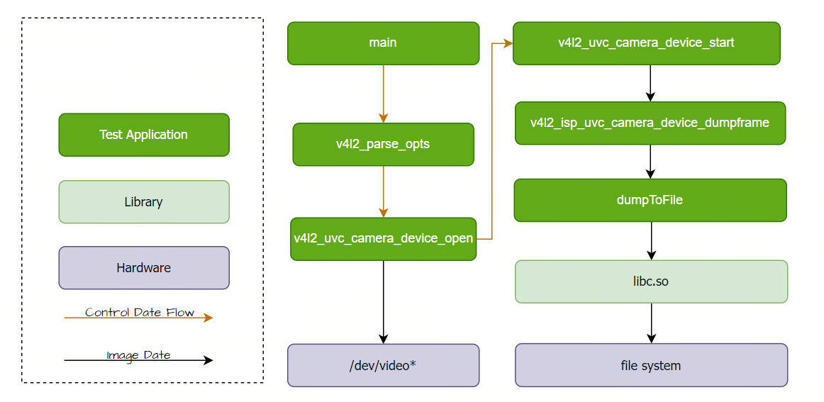
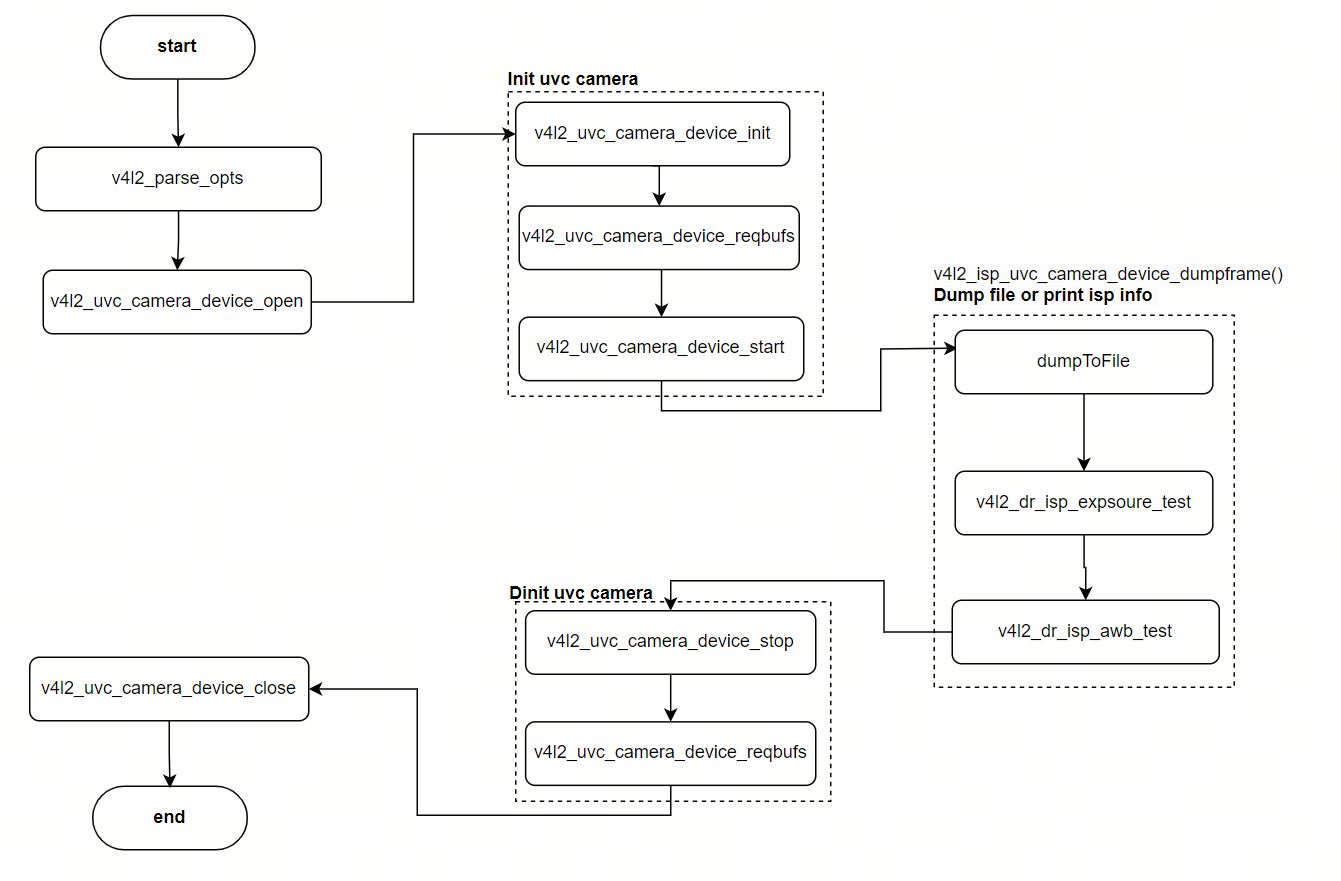
uvc_capture_sample is a program that tests the UVC camera video capture pipeline, performing image capture from a UVC camera and saving the output images. It also supports displaying ISP-related information.
Software Architecture Description
Code Location and Directory Structure
Code location:
app/samples/platform_samples/sample_pipeline/uvc_capture_sampleDirectory structure
uvc_capture_sample
├── Makefile
├── common_utils.c
├── common_utils.h
├── uvc_capture_sample.c
├── uvc_capture_sample.h
├── v4l2_common_utils.c
└── v4l2_common_utils.h
API Flow Description
3.15.12.2. Compilation and Deployment
Compilation
Enter the
uvc_capture_sampledirectory and runmaketo compile.The output binary is
uvc_capture_samplelocated in the source directory.For detailed compilation methods, refer to the Build Instructions section.
Program Deployment
After uploading the uvc_capture_sample directory to the development board, run chmod +x uvc_capture_sample to grant executable permissions.
3.15.12.3. Execution
How to Run the Program
Before running, connect a UVC camera to the development board’s USB HOST port.
Run ./uvc_capture_sample -h directly to get help information.
Program Parameter Options
Options:
-i, --video_id <id>Specifies the corresponding video node, such as video0, video1, etc.
The
/dev/videoXnodes in the system may serve different purposes. Use the following command to check supported formats and capabilities:
v4l2-ctl --device=/dev/videoX --list-formats-ext
-d, --dump_fileWhether to save image files. Enabling this option saves captured images as files.
-F, --formatSets the image format (e.g., YUYV, NV12), which must match the actual format supported by the UVC camera.
-l, --loop_cnt <num>Sets the number of capture cycles (i.e., number of frames to capture).
-H, --height <px>Sets the image height in pixels.
-W, --width <px>Sets the image width in pixels.
-E, --isp_infoDisplays ISP exposure and white balance information.
-H, --helpShows help information.
Examples:
Configure a UVC camera video pipeline using video0, set format to YUYV, and save 5 captured frames.
./uvc_capture_sample -i 0 -l 5 -W 1920 -H 1080 -F YUYV -d
Configure a UVC camera video pipeline using video0, set format to YUYV, save 5 captured frames, and print current exposure and white balance information.
./uvc_capture_sample -i 0 -l 5 -W 1920 -H 1080 -F YUYV -d -E
Execution Output
Run the following command:
./uvc_capture_sample -i 0 -l 5 -W 1920 -H 1080 -F YUYV -d
Sample log output:
ptc[0].video_id = 0
ptc[0].loop_cnt = 5
ptc[0].pic_width = 1920
ptc[0].pic_height = 1080
ptc[0].pic_format = 6
ptc[0].dump_mask = 1
DEBUG: index = 0, max_num = 24
pipe_num:0
TestContext[0] create pthread success
loop_cnt: 5
open device: /dev/video0 (fd=3)
     driver: uvcvideo
       card: FHD Camera Microphone: FHD Came
    version: 6.1.83
   all caps: 84a00001
device caps: 04200001
 0: Motion-JPEG 0x47504a4d 0x1
...
filedump(/userdata/yuv_dump/isp_5_s0_c0_b1_f0_005838.yuv, size(4147200) is successed
loop cnt use up
pipe(0)Test thread 281473524101408---join done.
------ Test case uvc_capture_sample done  ------
3.15.13. mp4_decode_and_display
3.15.13.1. Function Overview
The mp4_decode_and_display sample parses the H264 or H265 raw stream from MP4 files using the ffmpeg library, sends it to the VPU for decoding, and then displays it on an HDMI monitor.
The program also supports specifying playback position after startup: after the program executes, you can specify the current playback position via command line.
Note:
An HDMI monitor must be connected, and the HDMI monitor must support the resolution of the video file in the MP4
Since the decoder can only start decoding from key frames, when the specified position is not a key frame, it will select an appropriate position near the specified position to start playback
Software Architecture
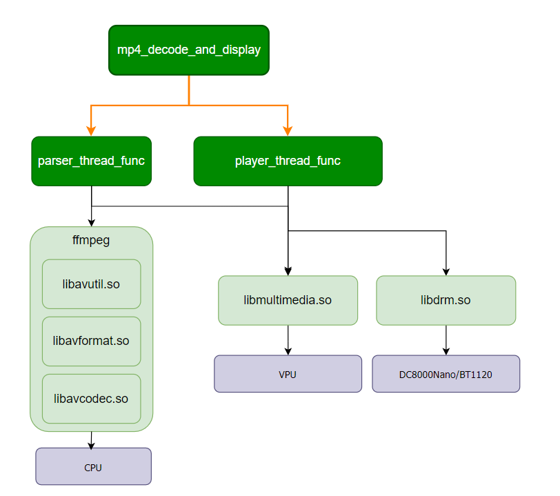
Data Flow

Code Location and Directory Structure
Code location:
app/samples/platform_samples/sample_pipeline/mp4_decode_and_displayDirectory structure:
mp4_decode_and_display
.
├── Makefile
├── codec_helper.c
├── codec_helper.h
├── mp4_decode_and_display.c
├── uthash.h
├── vp_codec.c
├── vp_codec.h
├── vp_display.c
└── vp_display.h
API Flow
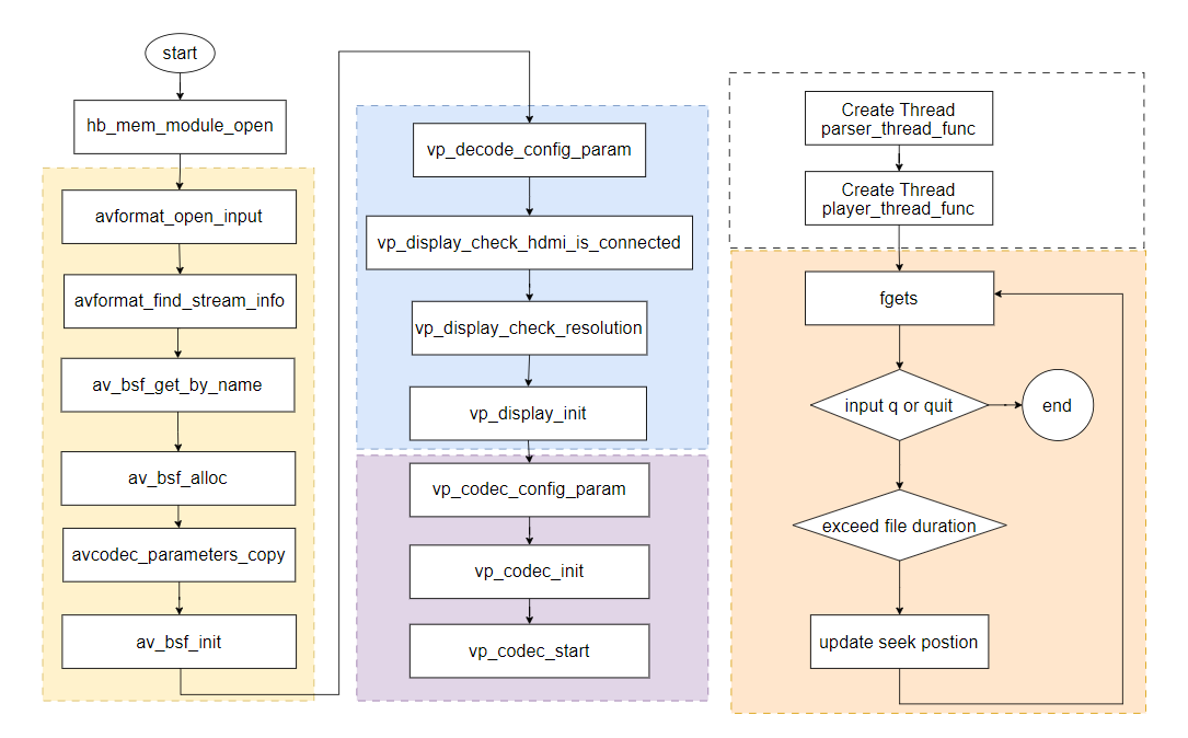
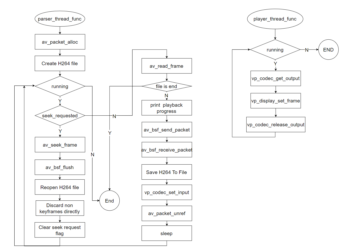
3.15.13.2. Build and Deployment
Build
Navigate to the mp4_decode_and_display directory and run
maketo buildThe output artifact is
mp4_decode_and_displayin the source code directoryFor detailed build instructions, please refer to the Build Method section
Deployment
After uploading mp4_decode_and_display to the development board, run chmod +x mp4_decode_and_display to grant executable permissions.
3.15.13.3. Running
The following preparations are needed before running:
MP4 format video file
HDMI display screen, and the display screen must support the resolution of the video in the MP4 video file
How to Run
Execute ./mp4_decode_and_display directly to get help information
Program Parameter Options
./mp4_decode_and_display
Usage: ./mp4_decode_and_display <input_mp4_file>
Example: ./mp4_decode_and_display input.mp4
Parameter description:
input_mp4_file: Specify the MP4 file
Running Results
The execution results of mp4_decode_and_display are as follows:
The video from the MP4 video file will be displayed on the HDMI display screen
Starting from the most recently specified playback position, save the H264 or H265 raw stream to file output.h264 or output.h265
Enter a number in the command line to specify the playback position
Enter q or quit to exit the program, or press Enter after the file finishes playing to also exit the program
./mp4_decode_and_display ./20250829-172933.mp4
[MP4_PLAYER]Printf video info:
[MP4_PLAYER] Input file: ./20250829-172933.mp4
[MP4_PLAYER] Output file:
[MP4_PLAYER] Codec: h264
[MP4_PLAYER] Duration: 136 seconds
[MP4_PLAYER] Total frames: 3146
[MP4_PLAYER] Video FPS: 23.00 or TotalFrames/Duration: 23.13
[MP4_PLAYER] Codec: H264
[MP4_PLAYER] Resolution: 1920x1080


[MP4_PLAYER] hdmi is connected.
[Decoder] Decode idx: 0, init successful
[MP4_PLAYER] Init video decode instance 0 successful
[Decoder] Decode idx: 0, start successful
[MP4_PLAYER] Parser thread start.


[MP4_PLAYER] MP4 decoder started. Enter seek position in seconds (or 'q' to quit):
[MP4_PLAYER] Example: 30 (seek to 30 seconds)[MP4_PLAYER] Seek to (seconds):

[MP4_PLAYER] Player thread start.
[MP4_PLAYER] playback progress: 0/136 s
[MP4_PLAYER] playback progress: 1/136 s
[MP4_PLAYER] playback progress: 2/136 s
[MP4_PLAYER] playback progress: 3/136 s
[MP4_PLAYER] playback progress: 4/136 s
[MP4_PLAYER] playback progress: 5/136 s
q
[MP4_PLAYER] Quitting...
[MP4_PLAYER] Parse thread finished
[MP4_PLAYER] Player thread finished

DRM resources cleaned up.
[MP4_PLAYER] MP4 decoder stopped
3.15.14. single_pipe_vin_isp_vse_gpu2d
3.15.14.1. Function Overview
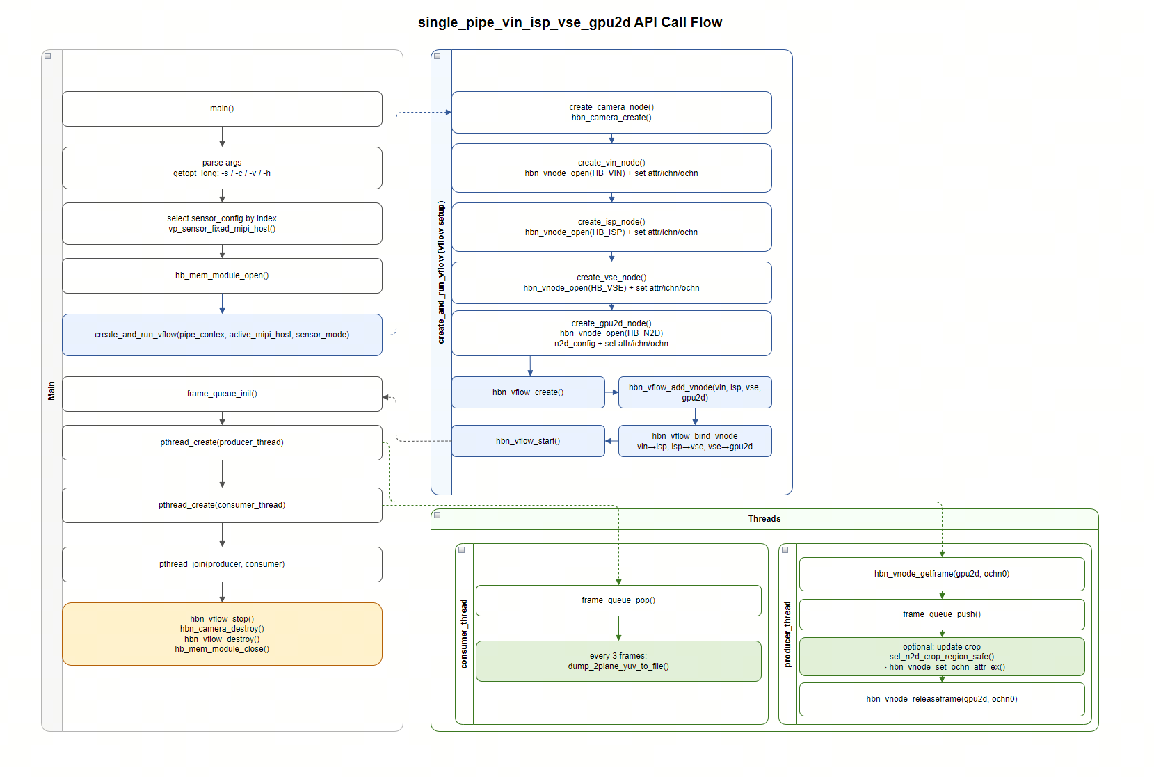
single_pipe_vin_isp_vse_gpu2d is a sample program for testing a single video pipeline, demonstrating the complete video processing chain from Sensor → VIN → ISP → VSE → GPU2D.
The core functions of the program are:
Complete signal processing through VIN, ISP, and VSE modules;
Use GPU2D module to perform image cropping and scaling;
Finally save NV12 images as .yuv files through queue processing.
Software Architecture
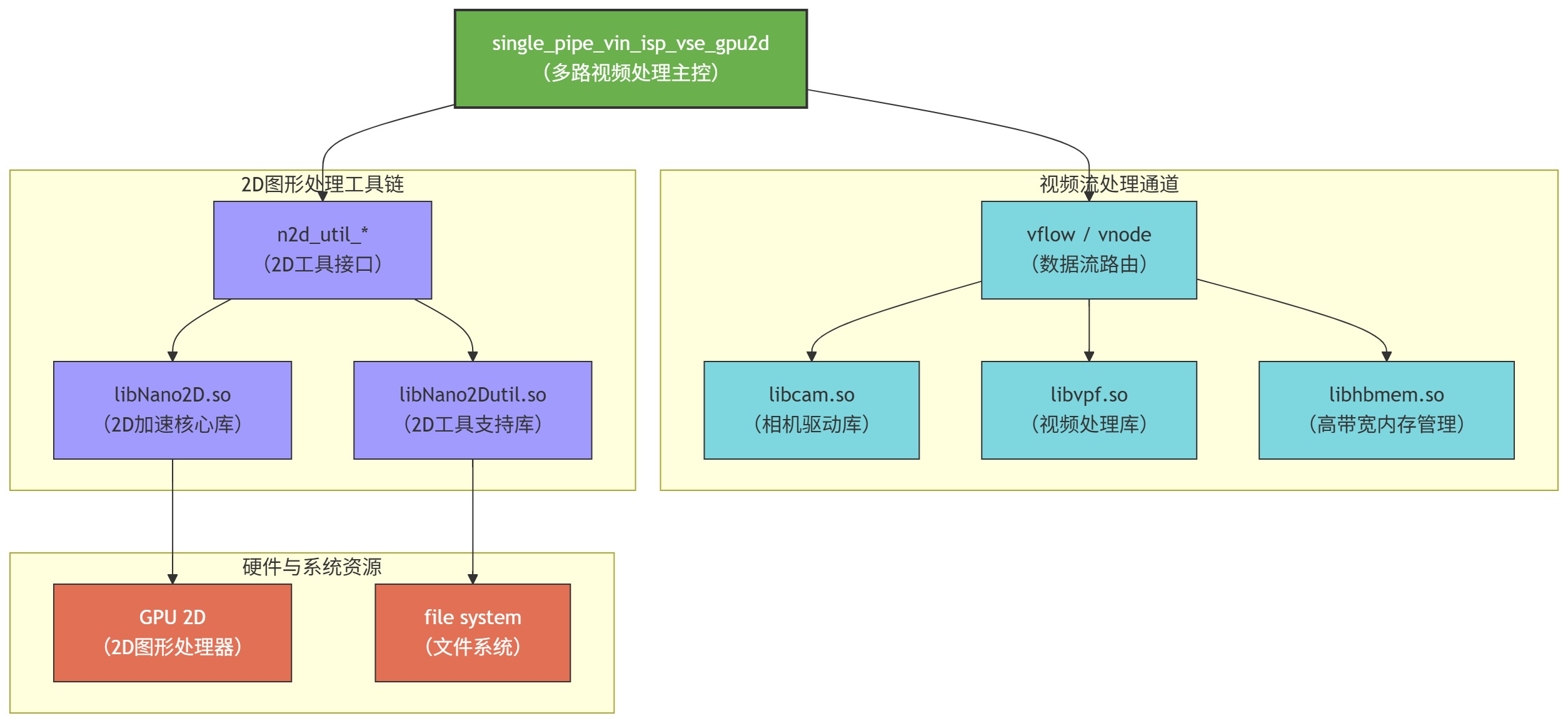
Data Flow

Code Location and Directory Structure
Code location:
app/samples/platform_samples/sample_pipeline/single_pipe_vin_isp_vse_gpu2dDirectory structure:
single_pipe_vin_isp_vse_gpu2d
├── Makefile
├── single_pipe_vin_isp_vse_gpu2d
└── single_pipe_vin_isp_vse_gpu2d.c
API Flow
3.15.14.2. Build and Deployment
Build
Navigate to the single_pipe_vin_isp_vse_gpu2d directory and run
maketo buildThe output artifact is
single_pipe_vin_isp_vse_gpu2din the source code directoryFor detailed build instructions, please refer to the Build Method section
Deployment
After uploading single_pipe_vin_isp_vse_gpu2d to the development board, run chmod +x single_pipe_vin_isp_vse_gpu2d to grant executable permissions.
3.15.14.3. Running
How to Run
Execute ./single_pipe_vin_isp_vse_gpu2d directly to get help information
Program Parameter Options
Usage: single_pipe_vin_isp_vse_gpu2d [options]
Options:
  -s <sensor_index>             Specify sensor index
  -v                            Enable verbose mode
  -c <channel_type>             Specify channel type: vo and vf and io and if, default: vf:if
                Support both individual configuration and combined configuration.
                The individual configuration supports four types:
                                1. vo: vin online isp
                                2. vf: vin offline isp
                                3. io: isp online vse
                                4. if: isp offline vse
                The combination configuration supports four types:
                                1. vo:io  vin online isp + isp online vse
                                2. vo:if  vin online isp + isp offline vse
                                3. vf:io  vin offline isp + isp online vse
                                4. vf:if  vin offline isp + isp offline vse
  -h    Show this help message
-s <sensor_index>Sensor index (required): integer type, corresponding to the sensor list printed by
vp_show_sensors_list().
-c <channel_type>Specify the online/offline combination between VIN→ISP and ISP→VSE. Default is
vf:if.Individual types:
vo/vf/io/ifCombined types:
vo:io/vo:if/vf:io/vf:if
-vEnable verbose mode to print more per-frame logs.
-hShow help information.
Running Results
This example demonstrates how to use single_pipe_vin_isp_vse_gpu2d with one imx219 sensor.
Run the following command:
./single_pipe_vin_isp_vse_gpu2d -s 30
Example log output:
root@buildroot:/userdata/app_test# ./single_pipe_vin_isp_vse_gpu2d -s 30
Verbose: 0
Using index:30  sensor_name:imx219-1920x1080-30fps  config_file:linear_1920x1080_raw10_30fps_2lane.c
[INFO] RDK board_id is 0x0503, so skip csi test for index 1 and index 3
mipi mclk is not configed.
Searching camera sensor on device: /proc/device-tree/soc/cam/vcon@0 i2c bus: 6 mipi rx phy: 0
INFO: Found sensor_name:imx219-1920x1080-30fps on mipi rx csi 0, i2c addr 0x10, config_file:linear_1920x1080_raw10_30fps_2lane.c
        Sensor name: imx219-1920x1080-30fps
        Active mipi host: 0
Connection method from VIN to ISP: vin offline isp
Connection method from VIN to ISP: isp offline vse.

csi0 ignore mclk ex attr, because not config mclk.
hbn_vnode_set_ochn_attr: 1920x1080
GPU2D input  1920x1080 stride=1920
GPU2D output 1920x1080 stride=1920
pthread_create
Running... Press Ctrl+C to exit
Saved frame to ./imx219-1920x1080-30fps_1920x1080_frameid0_ts_6076777994522.yuv ok
Saved frame to ./imx219-1920x1080-30fps_1920x1080_frameid3_ts_6076876729480.yuv ok
Saved frame to ./imx219-1920x1080-30fps_1920x1080_frameid6_ts_6076975461272.yuv ok
Saved frame to ./imx219-1920x1080-30fps_1920x1080_frameid9_ts_6077074194939.yuv ok
Saved frame to ./imx219-1920x1080-30fps_1920x1080_frameid12_ts_6077172930814.yuv ok
Saved frame to ./imx219-1920x1080-30fps_1920x1080_frameid15_ts_6077271669189.yuv ok
Saved frame to ./imx219-1920x1080-30fps_1920x1080_frameid18_ts_6077370402606.yuv ok
Saved frame to ./imx219-1920x1080-30fps_1920x1080_frameid21_ts_6077469136064.yuv ok
Saved frame to ./imx219-1920x1080-30fps_1920x1080_frameid24_ts_6077567869564.yuv ok
Saved frame to ./imx219-1920x1080-30fps_1920x1080_frameid27_ts_6077666604439.yuv ok
^CSaved frame to ./imx219-1920x1080-30fps_1920x1080_frameid30_ts_6077765336439.yuv ok
pthread_join success
...
After running, NV12-format YUV files will be saved, for example:
ls -alh
drwxr-xr-x  2 root root  36K Jan  1 06:29 .
drwxr-xr-x 16 root root 4.0K Jan  1 01:13 ..
-rw-r--r--  1 root root 3.0M Jan  1 06:29 imx219-1920x1080-30fps_1920x1080_frameid0_ts_6076777994522.yuv
-rw-r--r--  1 root root 3.0M Jan  1 06:29 imx219-1920x1080-30fps_1920x1080_frameid12_ts_6077172930814.yuv
-rw-r--r--  1 root root 3.0M Jan  1 06:29 imx219-1920x1080-30fps_1920x1080_frameid15_ts_6077271669189.yuv
-rw-r--r--  1 root root 3.0M Jan  1 06:29 imx219-1920x1080-30fps_1920x1080_frameid18_ts_6077370402606.yuv
-rw-r--r--  1 root root 3.0M Jan  1 06:29 imx219-1920x1080-30fps_1920x1080_frameid21_ts_6077469136064.yuv
-rw-r--r--  1 root root 3.0M Jan  1 06:29 imx219-1920x1080-30fps_1920x1080_frameid24_ts_6077567869564.yuv
-rw-r--r--  1 root root 3.0M Jan  1 06:29 imx219-1920x1080-30fps_1920x1080_frameid27_ts_6077666604439.yuv
-rw-r--r--  1 root root 3.0M Jan  1 06:29 imx219-1920x1080-30fps_1920x1080_frameid30_ts_6077765336439.yuv
3.15.15. single_pipe_vin_isp_vse_vo
3.15.15.1. Function Overview
single_pipe_vin_isp_vse_vo is a test sample program for verifying single-channel video capture and display functionality, demonstrating the complete video data flow processing chain from Sensor → VIN → ISP → VSE → HDMI display.
The core functions of the program are:
Complete signal processing through VIN, ISP, and VSE modules;
Use DRM interface (vp_display) to display images on HDMI in real-time;
Automatically match the resolution supported by the display device; if the current resolution is not in the supported list, the program will attempt to find the closest available resolution; if still unable to match, it will terminate and display an error message.
Software Architecture
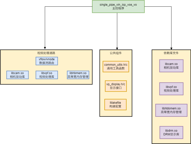
Data Flow

Code Location and Directory Structure
Code location:
app/samples/platform_samples/sample_pipeline/single_pipe_vin_isp_vse_voDirectory structure:
single_pipe_vin_isp_vse_vo
├── Makefile
├── single_pipe_vin_isp_vse_vo
└── single_pipe_vin_isp_vse_vo.c
API Flow
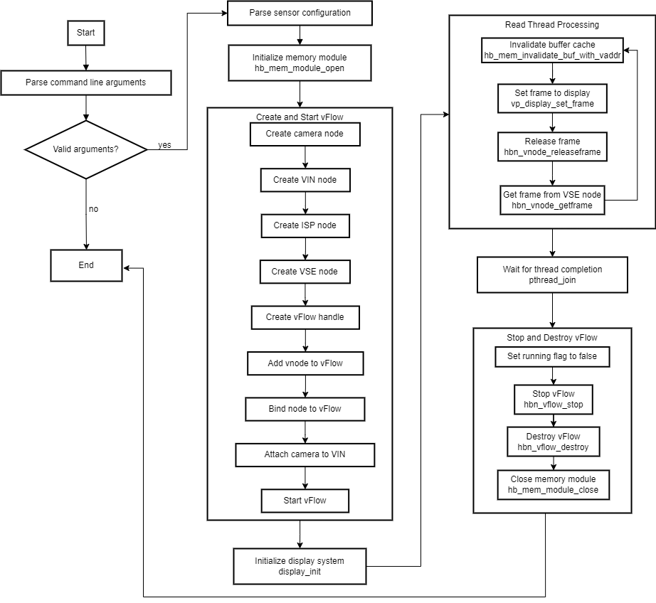
3.15.15.2. Build and Deployment
Build
Navigate to the single_pipe_vin_isp_vse_vo directory and run
maketo buildThe output artifact is
single_pipe_vin_isp_vse_voin the source code directoryFor detailed build instructions, please refer to the Build Method section
Deployment
After uploading single_pipe_vin_isp_vse_vo to the development board, run chmod +x single_pipe_vin_isp_vse_vo to grant executable permissions.
3.15.15.3. Running
How to Run
Before running the program, ensure the display device is properly connected: Connect the HDMI cable from the display to the HDMI output interface of the X5 board. Then, manually load the relevant driver modules to initialize the display subsystem.
modprobe panel-jc-050hd134
modprobe galcore
modprobe vio_n2d
modprobe lontium_lt8618
modprobe vs-x5-syscon-bridge
modprobe vs_drm
Execute ./single_pipe_vin_isp_vse_vo directly to get help information
Program Parameter Options
Usage: single_pipe_vin_isp_vse_vo [options]
Options:
  -s, --sensor <sensor_index>    Select sensor index to use
  -m, --mode <sensor_mode>       Select sensor mode (1:NORMAL_M, 2:DOL2_M, 6:SLAVE_M)
  -h, --help                     Show this help message
-s --sensor <sensor_index>sensor (required): Sensor index, integer type, corresponding to the sensor list in the system.
-m, --mode <sensor_mode>Select sensor mode.
Available values:
1 : NORMAL_M
2 : DOL2_M
6 : SLAVE_M
-h, --helpShow help information.
Running Results
This example demonstrates how to use single_pipe_vin_isp_vse_vo with one sc230ai sensor
Run the following command:
./single_pipe_vin_isp_vse_vo -s 3
Example log output:
Using index:3  sensor_name:sc230ai-30fps  config_file:linear_1920x1080_raw10_30fps_1lane.c
mipi mclk is configed.
Searching camera sensor on device: /proc/device-tree/soc/cam/vcon@0 i2c bus: 4 mipi rx phy: 0
INFO: Found sensor_name:sc230ai-30fps on mipi rx csi 0, i2c addr 0x30, config_file:linear_1920x1080_raw10_30fps_1lane.c
hbn_vnode_set_ochn_attr: 1920x1080
[   59.491765] hobot-sif 3d020000.sif: sif frame size incorrect, hsize count:0x0 vsize count:0x438 for inst:0
Checking resolutions:
Mode 0: 2560x1440 @ 60Hz
Mode 1: 3840x2160 @ 30Hz
Mode 2: 3840x2160 @ 30Hz
Mode 3: 3840x2160 @ 25Hz
Mode 4: 3840x2160 @ 24Hz
Mode 5: 3840x2160 @ 24Hz
Mode 6: 2560x1440 @ 100Hz
Mode 7: 2560x1440 @ 75Hz
Mode 8: 1920x1080 @ 60Hz
hdmi support resolution 1920*1080
------------------------------------------------------
Plane 0:
  Plane ID: 64
  Src W: 1920
  Src H: 1080
  CRTC X: 0
  CRTC Y: 0
  CRTC W: 1920
  CRTC H: 1080
  Format: NV12
  Z Pos: -1
  Alpha: -1
  Pixel Blend Mode: -1
  Rotation: -1
  Color Encoding: -1
  Color Range: -1
------------------------------------------------------
Setting up KMS...
Checking mode 2560x1440@60.00Hz
Checking mode 3840x2160@30.00Hz
Checking mode 3840x2160@29.97Hz
Checking mode 3840x2160@25.00Hz
Checking mode 3840x2160@24.00Hz
Checking mode 3840x2160@23.98Hz
Checking mode 2560x1440@100.00Hz
Checking mode 2560x1440@75.00Hz
Checking mode 1920x1080@60.00Hz
Found resolution match: 1920x1080@60.00Hz
Checking mode 1920x1080@60.00Hz
Checking mode 1920x1080@59.94Hz
Checking mode 1920x1080@60.00Hz
Checking mode 1920x1080@59.94Hz
Checking mode 1920x1080@50.00Hz
Checking mode 1920x1080@50.00Hz
Checking mode 1280x1440@59.91Hz
Checking mode 1680x1050@59.88Hz
Checking mode 1280x1024@75.02Hz
Checking mode 1280x1024@60.02Hz
Checking mode 1440x900@59.90Hz
Checking mode 1280x720@60.00Hz
Checking mode 1280x720@60.00Hz
Checking mode 1280x720@59.94Hz
Checking mode 1280x720@50.00Hz
Checking mode 1024x768@75.03Hz
Checking mode 1024x768@70.07Hz
Checking mode 1024x768@60.00Hz
Checking mode 832x624@74.55Hz
Checking mode 800x600@75.00Hz
Checking mode 800x600@72.19Hz
Checking mode 800x600@60.32Hz
Checking mode 800x600@56.25Hz
Checking mode 720x576@50.00Hz
Checking mode 720x576@50.00Hz
Checking mode 720x480@60.00Hz
Checking mode 720x480@60.00Hz
Checking mode 720x480@59.94Hz
Checking mode 720x480@59.94Hz
Checking mode 640x480@75.00Hz
Checking mode 640x480@72.81Hz
Checking mode 640x480@66.67Hz
Checking mode 640x480@60.00Hz
Checking mode 640x480@59.94Hz
Checking mode 640x480@59.94Hz
Checking mode 720x400@70.08Hz
Using resolution-matched mode: 1920x1080@60.00Hz
vp_display_init ok: 1920x1080 -> 1920x1080
...
After the program runs, the display will show the image content from the sensor in real-time.
3.15.16. single_format_convert_gpu2d
3.15.16.1. Function Overview
single_format_convert_gpu2d is a test example program for verifying image format conversion using 2D GPU. It demonstrates NV12 to BMP, NV12 to YUV422, YUV422 to BMP, and YUV422 to NV12 conversions.
The core functions of the program are:
Read the image file to be converted;
Create a 2D GPU node, and create and start a vflow;
Send data to and retrieve data from the 2D GPU node;
Save the retrieved data to the specified path.
Software Architecture Description
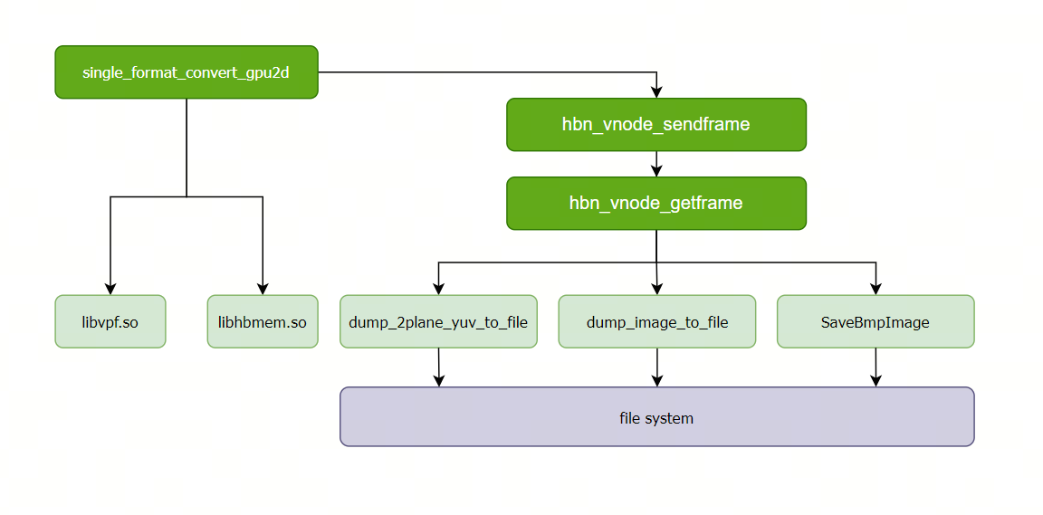
Code Location and Directory Structure
Code location:
app/samples/platform_samples/sample_pipeline/single_format_convert_gpu2dDirectory structure
single_format_convert_gpu2d
├── Makefile
├── bmp.c
├── bmp.h
├── res/nv12_1920x1080.yuv
├── res/yuv422_1920x1080.yuv422
├── single_format_convert_gpu2d
└── single_format_convert_gpu2d.c
API Flow Description
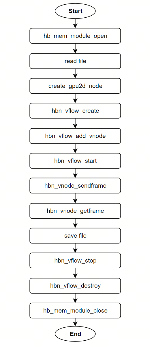
3.15.16.2. Build and Deployment
Build
Enter the
single_format_convert_gpu2ddirectory and runmaketo compileThe output binary is
single_format_convert_gpu2dlocated in the source directoryFor detailed compilation instructions, refer to the Build Method section
Program Deployment
After uploading single_format_convert_gpu2d and res to the development board, run chmod +x single_format_convert_gpu2d to grant execution permission.
3.15.16.3. Run
How to Run the Program
Execute the program directly with ./single_format_convert_gpu2d -h to display help information
Program Parameter Options
Usage: single_format_convert_gpu2d [OPTIONS]
Options:
  -i <input_img_name>       input image name
  -o <output_img_name>      output image name
  -w <image_width>          input image width
  -h <image_height>         input image height
  -j <input_img_format>     intput image format index
  -k <output_img_format>    output image format index
   MEM_PIX_FMT_ARGB    index is 4
   MEM_PIX_FMT_NV12    index is 8
   MEM_PIX_FMT_YUYV422 index is 13
  -h                        Show this help message
Such as: nv12 -> bmp yuv422:
        ./single_format_convert_gpu2d -i ./res/nv12_1920x1080.yuv  -o ./test_nv12_1920x1080.bmp -w 1920 -h 1080 -j 8 -k 3
        ./single_format_convert_gpu2d -i ./res/nv12_1920x1080.yuv  -o ./test_nv12_1920x1080.yuv422 -w 1920 -h 1080 -j 8 -k 13
         yuv422 -> bmp nv12:
        ./single_format_convert_gpu2d -i ./res/yuv422_1920x1080.yuv422 -o ./test_yuv422_1920x1080.bmp -w 1920 -h 1080 -j 13 -k 3
        ./single_format_convert_gpu2d -i ./res/yuv422_1920x1080.yuv422 -o ./test_yuv422_1920x1080.yuv -w 1920 -h 1080 -j 13 -k 8
Running Results
This example uses NV12 to BMP conversion to demonstrate how to use single_format_convert_gpu2d
Run the following command:
./single_format_convert_gpu2d -i ./res/nv12_1920x1080.yuv -o ./test_nv12_1920x1080.bmp -w 1920 -h 1080 -j 8 -k 3
Example log output:
buffer.addr:0xffffaa278000 size:2073600
(read_yuvv_nv12_file):file read(./res/nv12_1920x1080.yuv), y-size(2073600)
input_format is MEM_PIX_FMT_NV12
output_format is MEM_PIX_FMT_ARGB
GPU2D input  1920x1080 stride=1920
GPU2D output 1920x1080 stride=1920
SaveBmpImage ./test_nv12_1920x1080.bmp succ, size=8294400
After the program runs, a new file ‘test_nv12_1920x1080.bmp’ will appear in the current directory.
3.15.17. single_pipe_vin_isp_vse_multi_process
3.15.17.1. Function Overview
single_pipe_vin_isp_vse_multi_process is a multi-process communication sample program. It demonstrates how to obtain NV12 images from Sensor → VIN → ISP → VSE, and then send image frames to the following processes via UNIX domain sockets:
Encode process: send NV12 images to the VPU encoder and continuously save H.264 bitstream files;
HDMI display process: display NV12 images in real-time on an HDMI monitor via DRM.
This sample consists of 3 processes (executables):
single_pipe_vin_isp_vse_process: controller process. It is responsible for creating the vflow, getting frames from VSE and dispatching them to child processes, and receiving release messages from child processes;single_pipe_vin_isp_vse_hdmi: display process. It receives frames and displays them on HDMI;single_pipe_vin_isp_vse_encode: encode process. It receives frames and encodes/saves H.264 bitstream files (ping/pang rotation).
Software Architecture
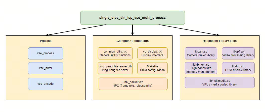
Data Flow
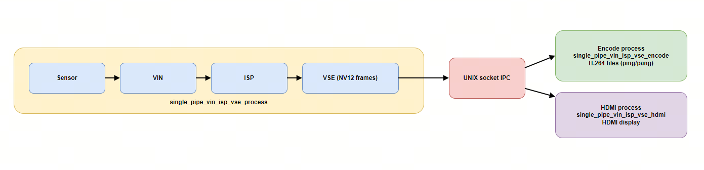
3.15.17.2. Function Flowcharts
VSE process: single_pipe_vin_isp_vse_process.c
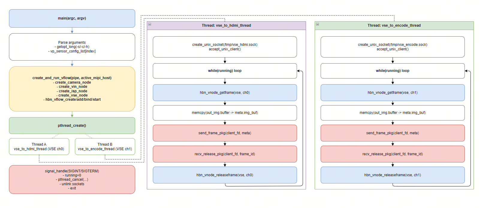
HDMI process: single_pipe_vin_isp_vse_hdmi.c
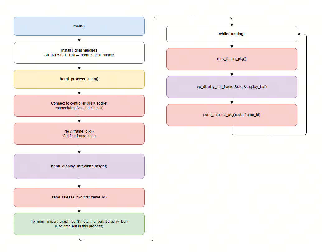
Encode process: single_pipe_vin_isp_vse_encode.c
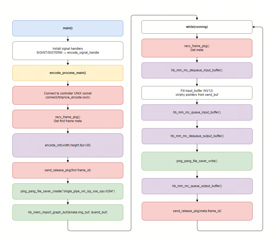
Code Location and Directory Structure
Code location:
app/samples/platform_samples/sample_pipeline/single_pipe_vin_isp_vse_multi_processDirectory structure:
single_pipe_vin_isp_vse_multi_process
├── Makefile
├── single_pipe_vin_isp_vse_process.c
├── single_pipe_vin_isp_vse_encode.c
├── single_pipe_vin_isp_vse_hdmi.c
├── unix_socket.c
├── unix_socket.h
├── ping_pang_file_saver.c
├── ping_pang_file_saver.h
3.15.17.3. Build and Deployment
Build
Navigate to the
single_pipe_vin_isp_vse_multi_processdirectory and runmaketo build.The output artifacts are three executables in this directory:
single_pipe_vin_isp_vse_processsingle_pipe_vin_isp_vse_encodesingle_pipe_vin_isp_vse_hdmi
For detailed build instructions, please refer to the Build Method section.
Deployment
After uploading the three executables to the development board, run chmod +x single_pipe_vin_isp_vse_* to grant executable permissions.
3.15.17.4. Running
How to Run
Before running the HDMI display process, ensure the display device is properly connected and load the display-related driver modules (same as single_pipe_vin_isp_vse_vo):
modprobe panel-jc-050hd134
modprobe galcore
modprobe vio_n2d
modprobe lontium_lt8618
modprobe vs-x5-syscon-bridge
modprobe vs_drm
It is recommended to use three terminals to start the three processes. Suggested start order:
Start the controller process
single_pipe_vin_isp_vse_processStart the HDMI display process
single_pipe_vin_isp_vse_hdmiStart the encode process
single_pipe_vin_isp_vse_encode
The encode/HDMI processes will actively connect to the sockets created by the controller process. If you start the encode/HDMI process first, it will print “please start VSE process first” and exit.
Program Parameter Options
The controller process single_pipe_vin_isp_vse_process supports the following options (the other two processes do not require arguments and can be run directly):
Usage: ./single_pipe_vin_isp_vse_process [OPTIONS]
Options:
  -s <sensor_index>             Specify sensor index
  -c <channel_type>             Specify channel type: vo and vf and io and if, default: vf:if
                Support both individual configuration and combined configuration.
                The individual configuration supports four types:
                                1. vo: vin online isp
                                2. vf: vin offline isp
                                3. io: isp online vse
                                4. if: isp offline vse
                The combination configuration supports four types:
                                1. vo:io  vin online isp + isp online vse
                                2. vo:if  vin online isp + isp offline vse
                                3. vf:io  vin offline isp + isp online vse
                                4. vf:if  vin offline isp + isp offline vse
  -h    Show help message
-s <sensor_index>Sensor index (required): integer type, corresponding to the sensor list in the system.
-c <channel_type>Specify the online/offline combination for VIN/ISP/VSE. Default is
vf:if.
-hShow help information and exit.
Running Results
This sample uses one sensor as an example to demonstrate how to use single_pipe_vin_isp_vse_multi_process.
Start the controller process first (example uses sensor index = 3):
./single_pipe_vin_isp_vse_process -s 3
Typical logs include:
Wait encode process connect...
Wait HDMI process connect...
In another terminal, start the HDMI display process:
./single_pipe_vin_isp_vse_hdmi
After a successful connection, the HDMI monitor will display images from VSE in real-time, and the terminal will output logs similar to:
HDMI display frame success: id=..., resolution=...x...
In another terminal, start the encode process:
./single_pipe_vin_isp_vse_encode
After a successful connection, the encode process will start printing received frame information, and will generate ping/pang rotated H.264 bitstream files in the current directory:
ping_single_pipe_vin_isp_vse_vpu.h264
To stop the program, press Ctrl+C in each terminal. The controller process will clean up /tmp/vse_encode.sock and /tmp/vse_hdmi.sock.
3.15.18. single_pipe_vin_isp_vse_bpu
3.15.18.1. Function Flowcharts
single_pipe_vin_isp_vse_bpu The example demonstrates how to transfer image data captured by the Camera to the BPU module for algorithm inference:
The program retrieves image data that has been scaled and matches the resolution requirements of the algorithm from output channel 1 of the VSE module
The algorithm demonstrated in this example is: mobilenetv2
Software Architecture
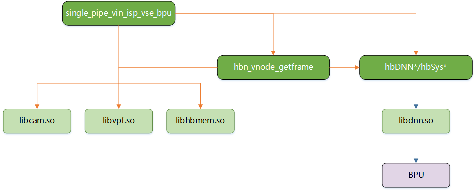
Data Flow
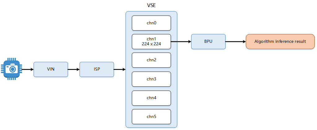
Code Location and Directory Structure
Code location
app/samples/platform_samples/sample_pipeline/single_pipe_vin_isp_vse_bpuDirectory structure
single_pipe_vin_isp_vse_bpu
├── bpu_mobilenetv2.c
├── bpu_mobilenetv2.h
├── Makefile
├── mobilenetv2_image_labels.h
├── model_zoom
│   └── mobilenetv2_224x224_nv12.bin
└── single_pipe_vin_isp_vse_bpu.c
API Flow Description
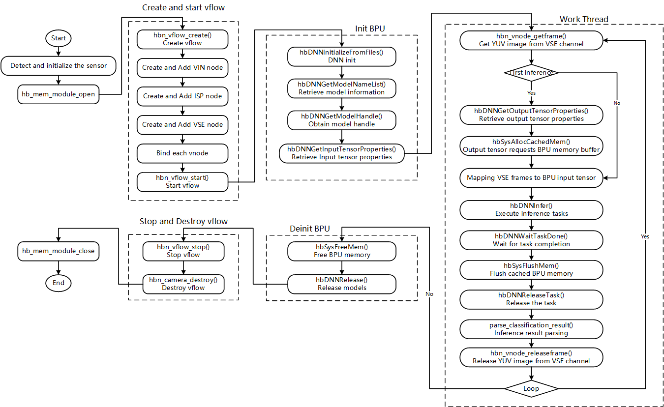
3.15.18.2. Build and Deployment
Build
Enter the
single_pipe_vin_isp_vse_bpudirectory and executemaketo compile.The output artifact is
single_pipe_vin_isp_vse_bpulocated in the source directory.For detailed compilation methods, please refer to the Compilation Methods section.
Deployment
After uploading single_pipe_vin_isp_vse_bpu and model_zoom to the development board, run the command chmod +x single_pipe_vin_isp_vse_bpu to grant executable permissions.
3.15.18.3. Running
How to Run
Directly execute the program ./single_pipe_vin_isp_vse to obtain help information.
Program Parameter Options
Usage: ./single_pipe_vin_isp_vse_bpu [OPTIONS]
Options:
  -s <sensor_index>             Specify sensor index
  -c <channel_type>             Specify channel type: vo and vf and io and if, default: vf:if
                Support both individual configuration and combined configuration.
                The individual configuration supports four types:
                                1. vo: vin online isp
                                2. vf: vin offline isp
                                3. io: isp online vse
                                4. if: isp offline vse
                The combination configuration supports four types:
                                1. vo:io  vin online isp + isp online vse
                                2. vo:if  vin online isp + isp offline vse
                                3. vf:io  vin offline isp + isp online vse
                                4. vf:if  vin offline isp + isp offline vse
  -h    Show help message
Parameter Description:
-s: Specify the Camera Sensor model and configuration.-c: Specify the connection methods between the designated VIN and ISP, and between the ISP and VSE, supporting both offline and online connection modes respectively.
Running Results
single_pipe_vin_isp_vse_bpu performs mobilenetv2 algorithm inference on the image captured by the camera and prints the inference result.
Example: Using sc230ai as the sensor input, execute ./single_pipe_vin_isp_vse -s 3 -c vf:if. Please select the corresponding index based on the currently connected sensor.
Using index:3  sensor_name:sc230ai-30fps  config_file:linear_1920x1080_raw10_30fps_1lane.c
mipi mclk is configed.
Searching camera sensor on device: /proc/device-tree/soc/cam/vcon@0 i2c bus: 4 mipi rx phy: 0
INFO: Found sensor_name:sc230ai-30fps on mipi rx csi 0, i2c addr 0x30, config_file:linear_1920x1080_raw10_30fps_1lane.c

Connection method from VIN to ISP: vin offline isp
Connection method from ISP to VSE: isp offline vse.

hbn_vnode_set_ochn_attr: 0, 1920x1080
hbn_vnode_set_ochn_attr: 1, 224x224
hbn_vnode_set_ochn_attr: 2, 224x224
hbn_vnode_set_ochn_attr: 3, 64x64
hbn_vnode_set_ochn_attr: 4, 480x480
hbn_vnode_set_ochn_attr: 5, 3840x2160
[BPU INFO] model_path[./model_zoom/mobilenetv2_224x224_nv12.bin]
[BPU_PLAT]BPU Platform Version(1.3.6)! soc info(x5)
[HBRT] set log level as 0. version = 3.15.55.0
[DNN] Runtime version = 1.24.5_(3.15.55 HBRT)
[A][DNN][packed_model.cpp:247][Model](1970-01-01,23:08:17.272.839) [HorizonRT] The model builder version = 1.23.0
[W][DNN]bpu_model_info.cpp:491][Version](1970-01-01,23:08:17.300.248) Model: mobilenetv2_224x224_nv12. Inconsistency between the hbrt library version 3.15.55.0 and the model build version 3.15.45.0 detected, in order to ensure correct model results, it is recommended to use compilation tools and the BPU SDK from the same OpenExplorer package.
Model info:
model_name: mobilenetv2_224x224_nv12
Input count: 1
input[0]: tensorLayout: 2 tensorType: 1 validShape:(1, 3, 224, 224, ), alignedShape:(1, 3, 224, 224, )
Output count: 1
Output[0]: tensorLayout: 2 tensorType: 13 validShape:(1, 1000, 1, 1, ), alignedShape:(1, 1000, 1, 1, )
[BPU INFO] model_name_list[0]:mobilenetv2_224x224_nv12
[BPU INFO] packed_dnn_handle: 0x2291840, dnn_handle: 0x22931f0
[BPU INFO] model input NCHW = (1, 3, 224, 224)
[BPU mobilenetv2] [classification result: id=572(goblet(酒杯)), score=0.095]
[BPU mobilenetv2] [classification result: id=794(shower curtain(浴帘)), score=0.149]
[BPU mobilenetv2] [classification result: id=807(solar dish(太阳能板)), score=0.224]
[BPU mobilenetv2] [classification result: id=461(breastplate(盔甲)), score=0.204]
[BPU mobilenetv2] [classification result: id=807(solar dish(太阳能板)), score=0.201]
... ...
... ...
... ...
[BPU mobilenetv2] [classification result: id=897(washer(洗衣机)), score=0.124]
[BPU mobilenetv2] [classification result: id=882(vacuum(吸尘器)), score=0.113]
[BPU mobilenetv2] [classification result: id=897(washer(洗衣机)), score=0.098]
[BPU mobilenetv2] [classification result: id=882(vacuum(吸尘器)), score=0.116]
[BPU mobilenetv2] [classification result: id=897(washer(洗衣机)), score=0.126]
^C[BPU mobilenetv2] [classification result: id=882(vacuum(吸尘器)), score=0.093]
[BPU INFO] bpu_wrap_deinit successful