3.13. sample_imu Usage Guide
3.13.1. Overview
3.13.1.1. Function Introduction
sample_imu provides multiple IMU data acquisition examples. Users can explore different data path reading methods through the subdirectories under sample_imu:
IIO path: Reads IIO device nodes via sysfs, supports interactive single-frame and multi-frame acquisition, and outputs data converted to SI units.
Input path: Reads driver-reported
EV_MSCevents through the Linux Input subsystem, suitable for verifying continuous driver reporting and packet loss.
3.13.1.2. Architecture Description of sample_imu
sample_imu contains multiple test cases. Each subdirectory is described as follows:
| Directory | Description |
|---|---|
| sample_imu_iio | Reads IMU data via the IIO interface, supporting bmi08x, icm42688-gyro, and icm42688-accel |
| sample_imu_input | Reads driver-reported IMU raw data via the Linux Input subsystem, with support for bmi08x and icm42688 |
3.13.2. sample_imu_iio
3.13.2.1. Functional Overview
sample_imu_iio is a command-line IMU example based on the IIO interface. It primarily implements the reading, processing, and display of Inertial Measurement Unit (IMU) data. With this program, users can conveniently obtain acceleration and gyroscope data from IMU sensors (magnetometer support can be extended if the sensor provides it), and perform corresponding analysis and applications.
The built-in supported sensor driver names are as follows:
bmi08xicm42688-gyroicm42688-accel
When no sensor is specified via -n, the program calls get_default_imu_name() to automatically detect the first available supported IIO device in the system. If no device is detected, the program reports that no device was found and then exits.
3.13.2.2. Software Architecture Description
sample_imu_iio adopts a layered design:
Application Layer:
sample_imu.cserves as the program entry point, responsible for parsing command-line arguments, initializing sensors, handling user input commands, and reading and displaying sensor data.Management Layer:
imu_manager.handimu_manager.cprovide sensor management interfaces, including listing available sensors, initializing sensors, reading data, and releasing resources.Adaptation Layer:
imu_interface.hdefines the sensor driver interface structure, providing a unified abstraction for specific sensors.Sensor Abstraction Layer: Files such as
bmi08x.candicm42688.cinteract with the underlying IIO drivers and convert hardware data into standard data formats usable by upper layers.
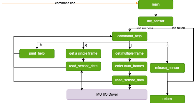
Software architecture diagram:
3.13.2.3. Data Flow Description
The application layer uses
init_sensor()to find and validate the target IIO device under/sys/bus/iio/devices/.The sensor abstraction layer reads raw values from nodes such as
in_accel_*_rawandin_anglvel_*_raw, and converts them to physical quantities using scale.The application layer obtains one frame of
ImuDataviaread_sensor_data(), then callsprint_imu_data()to output acceleration (m/s²), angular velocity (rad/s), and timestamp.
3.13.2.4. Code Location and Directory Structure
Code location:
app/samples/platform_samples/sample_imu/sample_imu_iioDirectory structure
sample_imu_iio
├── Makefile
├── bmi08x.c
├── icm42688.c
├── imu_interface.h
├── imu_manager.c
├── imu_manager.h
└── sample_imu.c
Description of each file:
Makefile: Defines compilation rules; the build output is
sample_imu_iio.sample_imu.c: Program entry point, responsible for command-line parsing and interactive data reading.
imu_manager.c / imu_manager.h: Sensor management and IIO device detection logic.
imu_interface.h: Unified sensor driver interface definition.
bmi08x.c: BMI08x sensor abstraction layer implementation.
icm42688.c: ICM42688 accelerometer/gyroscope abstraction layer implementation.
To add other IMU sensors, refer to the implementation in bmi08x.c and extend according to the interfaces in imu_interface.h.
3.13.2.5. Background Knowledge
An Inertial Measurement Unit (IMU) is a device used to measure physical quantities such as acceleration, angular velocity, and magnetic field strength of an object. It typically consists of an accelerometer, gyroscope, and magnetometer. By measuring and analyzing these physical quantities, information about the object’s orientation and motion state can be obtained. It should be noted that not all IMUs include all three sensors; in the industry, accelerometers, gyroscopes, and magnetometers are sometimes sold separately, while other IMUs are available in 6-axis or 9-axis configurations.
3.13.2.6. API Process Description
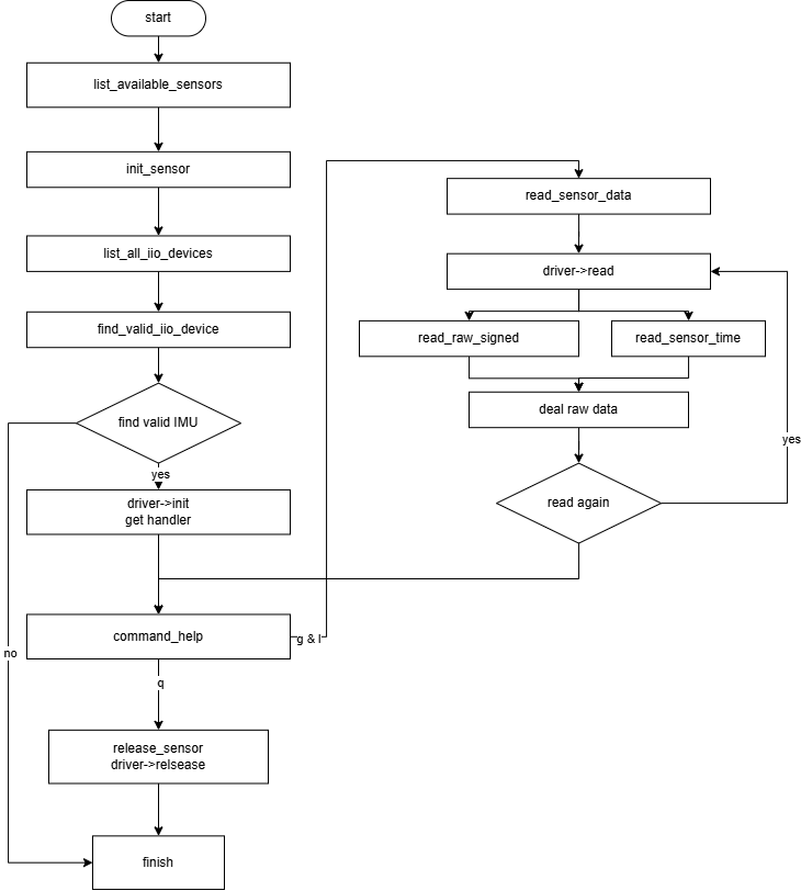
sample_imu_iio is built primarily on standard kernel IIO interfaces. The overall process based on program functions is as follows:
List available sensors: Call
list_available_sensors()to traverse the built-in supported sensor driver list and print the names.Initialize sensor: Call
init_sensor(), passing the sensor type to find and validate the corresponding IIO device, then call the specific driver initialization function.Read sensor data: Call
read_sensor_data(); the sensor abstraction layer reads one frame of data and fillsImuData.Release sensor resources: Call
release_sensor()to release the driver context and handle.
3.13.2.7. Compilation and Deployment
Compilation
Enter the
sample_imu_iiodirectory and runmaketo compileThe output is
sample_imu_iioin the source directoryFor detailed compilation instructions, refer to the Compilation Method section
Hardware Environment Setup
Refer to the following connection method (using BMI08x sensor):
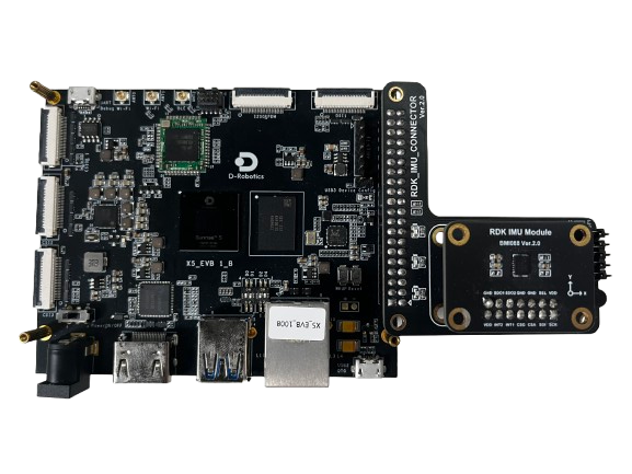
After confirming the hardware connection is correct, verify whether the corresponding driver configuration is enabled. (Since this sensor is not an onboard device, the following configurations may be disabled by default in the SDK. Please check whether they are enabled in the actual code before use.)
First, check the dts file. For the EVB board, the x5-evb.dtsi file is used. Check whether the corresponding i2c5 node is configured. If not, refer to the following configuration:
&i2c5 {
	status = "okay";
    ......
	bmi08a@19 {
		compatible = "bmi08xa";
		reg = <0x19>;
		interrupt-parent = <&ls_gpio1_porta>;
		interrupts = <4 IRQ_TYPE_EDGE_RISING>;
		status = "okay";
	};

	bmi08g@69 {
		compatible = "bmi08xg";
		reg = <0x69>;
		interrupt-parent = <&ls_gpio1_porta>;
		interrupts = <6 IRQ_TYPE_EDGE_RISING>;
		status = "okay";
	};
};
This IMU also supports the SPI interface. If you want to use SPI, refer to the device tree configuration below:
&spi1 {
	/*When dual chip select is used, the number of SPI chip selects must be set to 2.*/
	/*num-cs = <2>;*/
	status = "okay";
	pinctrl-names = "default";
	pinctrl-0 = <&pinctrl_spi1 &pinctrl_spi1_ssn1>;
	dma-names = "tx", "rx";
	dmas = <&axi_dmac 23>, <&axi_dmac 22>;

	bmi08g@0 {
		compatible = "bmi088_gyro";
		reg = <0>;
		spi-max-frequency = <5000000>;
		interrupt-parent = <&dsp_gpio_porta>;
		interrupts = <12 IRQ_TYPE_EDGE_RISING>;
		gyro-irq-gpio = <&dsp_gpio_porta 12 GPIO_ACTIVE_HIGH>;
		status = "okay";
	};

	bmi08a@1 {
		compatible = "bmi08a";
		reg = <1>;
		spi-max-frequency = <5000000>;
		interrupt-parent = <&ls_gpio0_porta>;
		interrupts = <2 IRQ_TYPE_EDGE_RISING>;
		accel-irq-gpio = <&ls_gpio0_porta 2 GPIO_ACTIVE_HIGH>;
		status = "okay";
	};
};
Note: Only one interface (I2C or SPI) can be used at a time. Unused interfaces can be set to disabled in the device tree.
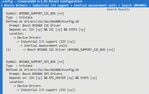
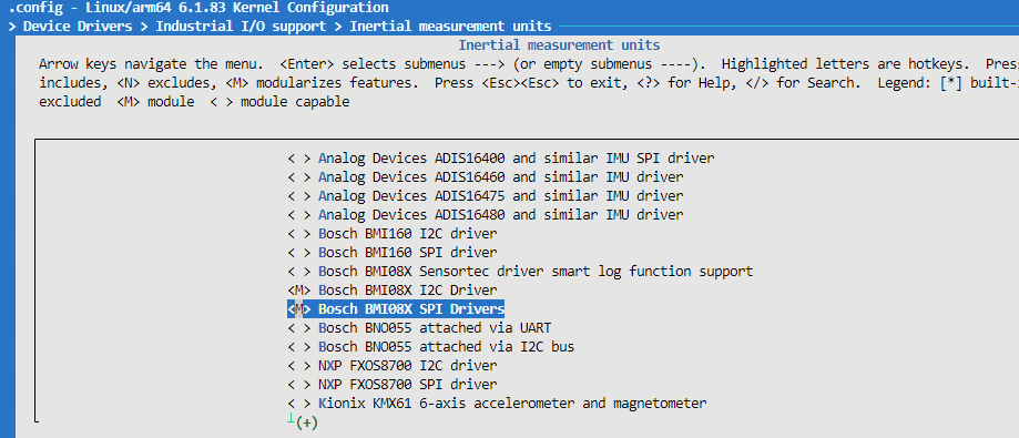
Then check whether the corresponding defconfig (e.g., hobot_x5_soc_defconfig used by default on EVB) has enabled:
CONFIG_BMI08X_SUPPORT_I2C_BUS=m
CONFIG_BMI08X_SUPPORT_SPI_BUS=m
These can be enabled via menuconfig. The search location can refer to the screenshot below:
The enabling method can refer to the screenshot below:
Finally, compile the entire image and flash it. After flashing, check whether the IMU has been successfully registered using one of the following two methods:
(1) Check via LOG:
root@buildroot:~# dmesg | grep BS
[    0.084965] CPU features: detected: Speculative Store Bypassing Safe (SSBS)
               [I]\x016<BS_LOG><bmi08_i2c_probe><187>client->name:bmi08xa / addr: 0x19
               [I]\x016<BS_LOG><bmi08_i2c_probe><187>client->name:bmi08xg / addr: 0x69
               [I]\x016<BS_LOG><sensor_init><1057>accel initilized
               [I]\x016<BS_LOG><sensor_init><1064>gyro initilized
               [I]\x016<BS_LOG><sensor_init><1065>sensor initilized
               [I]\x016<BS_LOG><sensor_init><1072>soft reset done
               [I]\x016<BS_LOG><sensor_init><1080>config stream loaded successfully
               [I]\x016<BS_LOG><sensor_init><1090>Accel power mode set to NORMAL
               [I]\x016<BS_LOG><sensor_init><1099>Gyro power mode set to NORMAL
               [I]\x016<BS_LOG><bmi08_probe><2216>Acc chip ID : 0x1e, Gyro chip ID : 0xf
               [I]\x016<BS_LOG><bmi08_request_irq><544>ACC IRQ requested for pin : 56
               [I]\x016<BS_LOG><bmi08_probe><2227>ACC IRQ requested
               [I]\x016<BS_LOG><bmi08_gyr_request_irq><563>GYR IRQ requested for pin : 57
               [I]\x016<BS_LOG><bmi08_probe><2234>GYR IRQ requested
               [I]\x016<BS_LOG><bmi08_probe><2236>sensor bmi088 probed successfully
[    4.687140] CAM_SUBSYS soc:cam:cam_sys@0: [FRT:D] camsys_probe(0)
root@buildroot:~#
You can see the sensor ID has been read correctly:
[I]\x016<BS_LOG><bmi08_probe><2216>Acc chip ID : 0x1e, Gyro chip ID : 0xf
(2) Check the name node in the IIO subsystem:
root@buildroot:~# cd /sys/bus/iio/devices/iio\:device1/
root@buildroot:/sys/bus/iio/devices/iio:device1# cat name
bmi08x
root@buildroot:/sys/bus/iio/devices/iio:device1#
Program Deployment
After uploading sample_imu_iio to the development board, run chmod +x sample_imu_iio to grant executable permission.
Default deployment path on board:
/app/platform_samples/sample_imu/sample_imu_iio/sample_imu_iio
3.13.2.8. Running
Program Usage Method
Run the program directly to obtain help information:
./sample_imu_iio -h
When run without parameters, the program automatically detects and uses the first available supported IMU in the system:
./sample_imu_iio
You can also explicitly specify the sensor name via -n, for example:
./sample_imu_iio -n bmi08x
./sample_imu_iio -n icm42688-gyro
Program Parameter Options Description
Usage: sample_imu_iio [OPTIONS]
Options:
  -n <imu_name>         Specify IMU name (default: auto-detected)
  -h                    Show this help message
Supported sensors: bmi08x icm42688-gyro icm42688-accel
Parameter description:
-n <imu_name>: Specifies the IMU sensor name. If not specified, the program automatically detects the first available device.-h: Displays help information and lists the built-in supported sensor names.
Running Effect
After the program runs, it displays a command menu where users can input commands to retrieve sensor data:
root@buildroot:/app/platform_samples/sample_imu/sample_imu_iio# ./sample_imu_iio
No IMU specified, using detected default: bmi08x
Using IMU: bmi08x

=== Detected IIO Devices ===
  Device: iio:device1     | Name: bmi08x
  Device: iio:device0     | Name: 34190000.adc
============================

Device validation passed at: /sys/bus/iio/devices/iio:device1
BMI08x: Initializing with params:

***************  Command Lists  ***************
 g    -- Get a single frame of imu data
 l    -- Get multiple frames of imu data
 q    -- Quit the program
 h    -- Print this help message
Enter command:
Command description:
g: Get one frame of IMU data.l: Get multiple frames of IMU data; requires entering the number of frames.q: Quit the program.h: Display help information.
Example of getting one frame of data:
Enter command: g
Data received (Frame 1):
  Accelerometer: [-117.836021, -118.283142, 9.569026] m/s²
  Gyroscope:     [0.006392, -69.885605, 0.049002] rad/s
  Timestamp:     00:01:38.917.929
Example of getting multiple frames of data:
Enter command: l
Enter number of frames to read: 3
Data received (Frame 1):
  Accelerometer: [-117.870140, -118.261597, 9.597756] m/s²
  Gyroscope:     [0.019175, 0.010653, -69.857903] rad/s
  Timestamp:     00:01:50.861.640
Data received (Frame 2):
  Accelerometer: [-117.825249, -118.283142, 9.574412] m/s²
  Gyroscope:     [0.014914, -69.857903, -69.887733] rad/s
  Timestamp:     00:01:50.867.500
......
3.13.2.9. Common Issues
Device connected but not recognized
First, ensure the hardware connection is correct. Check whether the connection between the IMU and the development board is loose, short-circuited, or incorrectly connected. Refer to the 40PIN connection description in the development board user guide.
Second, check whether the driver has been properly registered with the IIO framework. When
sample_imu_iioruns, it lists all devices under IIO. If the expected device is not found, check the driver registration status. For details, refer to Hardware Environment Setup above.To support a new IMU model, first complete driver registration under the IIO framework, then extend the sensor abstraction layer in
sample_imu_iioby referring tobmi08x.c.
3.13.3. sample_imu_input
3.13.3.1. Functional Overview
sample_imu_input demonstrates how to read IMU data reported by the driver through the Linux Input subsystem. Unlike the sysfs polling/reading approach in sample_imu_iio, this example reads the /dev/input/eventX node, parses six-axis raw values, hardware timestamps, and IRQ counts continuously reported by the driver via EV_MSC events, and performs packet loss detection based on timestamp intervals.
Features of this example:
Continuously reads driver-reported events; no interactive
g/l/qmenuOutputs six-axis raw LSB values and 64-bit hardware timestamps (ns)
When the interval between adjacent frame timestamps exceeds 3.5 ms, it is treated as possible packet loss and a warning is printed
For prerequisites such as hardware connection, device tree, and kernel configuration, refer to sample_imu_iio Hardware Environment Setup. For basic IMU concepts, refer to Background Knowledge.
3.13.3.2. Software Architecture Description
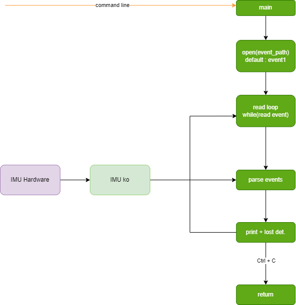
sample_imu_input.c starts from the main entry, opens the /dev/input/eventX device, and enters a read loop. Each time an input_event is read, it parses EV_MSC fields, assembles a frame on SYN_REPORT, prints six-axis data and timestamps, and performs packet loss detection based on adjacent frame timestamp intervals. The program runs continuously until the user presses Ctrl+C to exit.
Software architecture diagram:
3.13.3.3. Data Flow Description
After each sampling completes, the kernel BMI088 driver reports multiple
EV_MSCevents through the Input subsystem (code = BMI088_MSC_DATA).One frame ends with
SYN_REPORT; when the application receivesSYN_REPORT, it assembles the cached 9 MSC fields into one frame of IMU data.The application prints ACC/GYRO raw values, timestamp, and IRQ count, and statistics packet loss based on adjacent timestamp differences.
MSC field order per frame:
| Index | Meaning |
|---|---|
| 0 ~ 2 | Accelerometer X/Y/Z raw values |
| 3 ~ 5 | Gyroscope X/Y/Z raw values |
| 6 ~ 7 | Hardware timestamp high/low 32 bits |
| 8 | IRQ count |
3.13.3.4. Code Location and Directory Structure
Code location:
app/samples/platform_samples/sample_imu/sample_imu_inputDirectory structure
sample_imu_input
├── Makefile
├── sample_imu_input.c
└── sample_imu_input
3.13.3.5. API Process Description
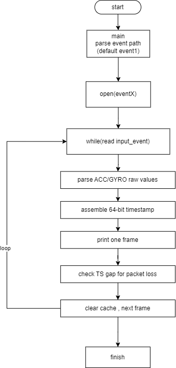
sample_imu_input is implemented based on standard Linux Input interfaces. The main process is as follows:
open()opens the/dev/input/eventXdevice node.Loop
read()to read theinput_eventstructure.Cache fields on
EV_MSCevents; assemble and print the frame onSYN_REPORTevents.Determine packet loss based on the difference between adjacent hardware timestamps.
On program exit,
close()the device and output statistics.
3.13.3.6. Compilation and Deployment
Compilation
Enter the
sample_imu_inputdirectory and runmaketo compileThe output is
sample_imu_inputin the source directoryFor detailed compilation instructions, refer to the Compilation Method section
Program Deployment
After uploading sample_imu_input to the development board, run chmod +x sample_imu_input to grant executable permission.
Default deployment path on board:
/app/platform_samples/sample_imu/sample_imu_input/sample_imu_input
After the driver is loaded successfully, you can confirm the Input device node with the following commands:
cat /proc/bus/input/devices
ls -l /dev/input/event*
Select the correct event node according to the actual device name; the program uses /dev/input/event1 by default.
3.13.3.7. Running
Program Usage Method
Use the default device node:
./sample_imu_input
Specify the Input device path:
./sample_imu_input /dev/input/event2
After the program starts, it continuously reads and prints data. Press Ctrl+C to exit.
Program Parameter Options Description
This program does not use getopt-style parameters. It supports the following invocation:
./sample_imu_input [input_device_path]
input_device_path(optional): Input device node path; default is/dev/input/event1.
Running Effect
========================================
BMI088 input reader (unified MSC code)
Device path: /dev/input/event1
Press Ctrl+C to exit
========================================

ACC(-117,-118,9) | GYRO(0,-69,0) | TS:9876543210 ns | Lost: 0 | EventCount: 9 | up_count: 128 | lower_count: -
ACC(-117,-118,9) | GYRO(0,-69,0) | TS:9879876543 ns | Lost: 0 | EventCount: 9 | up_count: 129 | lower_count: -
[ERROR] IMU data lost: last ts 0.009876s, current ts 0.009883s, diff 0.000007s
......
Field description:
ACC(x,y,z)/GYRO(x,y,z): Six-axis raw LSB valuesTS: Hardware timestamp (ns) assembled from high/low 32 bits reported by the driverLost: Cumulative suspected packet loss countEventCount: Number of input events received in the current frameup_count: IRQ count reported by the driver[ERROR] IMU data lost: Packet loss indicator; the packet loss time interval threshold may need to be modified in the program according to specific solution requirements.
3.13.3.8. Common Issues
Failed to open /dev/input/eventX
First confirm that the IMU driver has been loaded successfully. For hardware connection and kernel configuration, refer to sample_imu_iio Hardware Environment Setup.
Use
cat /proc/bus/input/devicesto confirm theeventnode number corresponding to the IMU, and pass the correct path in the startup command.
Device opens but no data is output
Confirm that the driver has enabled data stream reporting; in some scenarios, IIO/Input driver probe and interrupt configuration must be completed first.
Check whether the wrong
eventnode was selected (other Input devices such as keyboard or touchpad may exist in the system).
How to determine packet loss
By default, the program uses an adjacent frame hardware timestamp difference greater than 3.5 ms as the packet loss threshold; when packet loss occurs, it prints the
[ERROR] IMU data lostlog.