3.6. sample_gdc Usage Instructions
The sample_gdc directory contains example programs demonstrating how to use the GDC module. The main functions are described as follows:
generate_custom_config.py: Generates calibration configuration parameters for GDC.generate_bin: Reads a local JSON configuration file and generates the correspondinggdc.binfile.gdc_static_valid: Reads a localgdc.binfile and an original YUV file, processes the data through GDC, and saves the output as a YUV file.gdc_stress_test: Reads a localgdc.binfile and continuously feeds an original YUV file into GDC for performance testing.gdc_equisolid: Reads a local NV12 YUV image and applies (panoramic) correction processing via GDC.gdc_transformation: Reads a local JSON configuration file and applies 180-degree linear transformation, cylindrical transformation, equidistant transformation, and trapezoidal correction with distortion removal through GDC.
The usage scenarios of GDC follow roughly the same process at the API level on the target device, differing only in the configuration parameter files (layout.json) used by the GDC module when generating the bin file.
The configuration parameter files for the GDC module must be generated using the GDC Tool. Refer to GDC Tool Introduction.
3.6.1. 1-custom_config
3.6.1.1. Overview
This example demonstrates how to prepare input images in advance using custom transformation and generate calibration parameter files to guide GDC correction.
3.6.1.2. Code Location and Directory Structure
Code location:
app/samples/platform_samples/sample_gdcDirectory structure
sample_gdc/
├── 1-custom_config
│   ├── Makefile
│   ├── chessboard
│   ├── chessboard.png
│   ├── custom_config.txt
│   └── generate_custom_config.py
3.6.1.3. Development and Usage Procedure
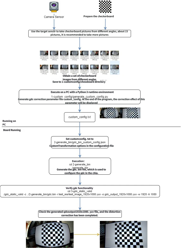
On a PC, use the generate_custom_config.py program to generate GDC correction calibration parameters.
Prepare a chessboard pattern image (
chessboard.png), which can be printed or displayed on a monitor.Use the target Camera Sensor to capture the chessboard image from different angles, taking about 15 images; it is recommended to take more.
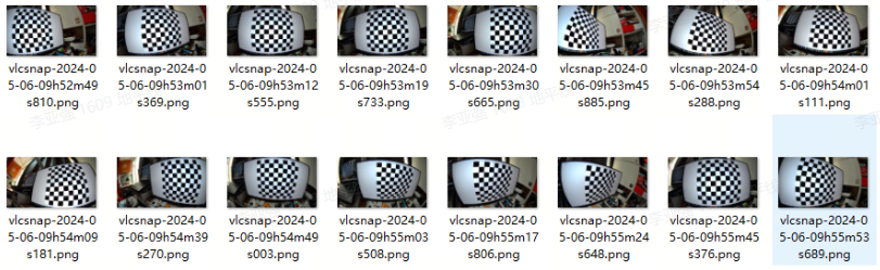
Using the above chessboard images as input, run the following Python script (ensure the system supports Python 3 and has the
opencv-pythonlibrary installed) to generate the GDC correction calibration parameter file (custom_config.txt):cd 1-custom_config python3 ./generate_custom_config.py
Log output in terminal:
No graphical environment detected. Skipping display of images.
Input images directory: ./chessboard
Test image file: ./chessboard/vlcsnap-2024-05-06-09h53m19s733.jpg
Output file: custom_config.txt
i: 0
i: 1
... omitted ...
i: 15
Intrinsic matrix (mtx):
 [[784.57179685   0.         939.01168998]
 [  0.         784.35388599 554.71639175]
 [  0.           0.           1.        ]]
Distortion coefficients (dist):
 [[-3.16520533e-01  1.02422375e-01 -2.60692201e-04  7.23624256e-04
  -1.44726239e-02]]
Rotation vectors (rvecs):
 (array([[-0.07424795],
       [ 0.17820099],
       [-0.04684888]]), array([[0.44453246],
       [0.01540531],
       [0.03596364]]), array([[-0.38217217],
       [-0.4097845 ],
       [ 0.16419408]]), array([[-0.0713388 ],
       [-0.04356189],
       [ 0.00918689]]), array([[ 0.40326625],
       [-0.65705694],
       [ 0.07152059]]), array([[-0.28933582],
       [ 0.07433653],
       [ 0.09031559]]), array([[-0.1353966 ],
       [-0.61689018],
       [-0.06274773]]), array([[ 0.02193021],
       [-0.52159079],
       [ 0.08910704]]), array([[-0.10002557],
       [-0.25580186],
       [-0.08683701]]), array([[-0.37827059],
       [-0.98115358],
       [ 0.175653  ]]), array([[0.33652166],
       [0.12869965],
       [0.03961734]]), array([[ 0.40214666],
       [-0.38128926],
       [-0.0051477 ]]), array([[-0.04168182],
       [ 0.0922567 ],
       [-0.03109347]]))
Translation vectors (tvecs):
 (array([[ -71.275847  ],
       [-106.35748096],
       [ 224.27593215]]), array([[  3.80981104],
       [-81.7694762 ],
       [183.44645072]]), array([[ -81.59651772],
       [-122.67796656],
       [ 240.51602851]]), array([[ -86.84292041],
       [-114.12437351],
       [ 203.11264832]]), array([[-51.05204629],
       [-57.97011932],
       [168.23228488]]), array([[ -25.79903668],
       [-139.06100345],
       [ 248.06228137]]), array([[ -91.12813213],
       [-111.74470892],
       [ 150.61397733]]), array([[ -89.4296275 ],
       [-117.79736921],
       [ 196.30732053]]), array([[ -89.4296275 ],
       [-117.79736921],
       [ 196.30732053]]), array([[-156.41212161],
       [-146.02467216],
       [ 191.13039641]]), array([[ -60.65720996],
       [-111.66378957],
       [ 191.3402483 ]]), array([[-56.56159122],
       [-72.97166982],
       [149.97470497]]), array([[ -60.28586566],
       [-111.66429463],
       [ 196.1187917 ]]))
New camera matrix (newcameramtx):
 [[784.57179685   0.         939.01168998]
 [  0.         784.35388599 554.71639175]
 [  0.           0.           1.        ]]
Validation of distortion correction
Saving mapx and mapy to 'custom_config.txt'
No graphical environment detected. The output image has been saved to 'custom_config.txt'.
If running in a graphical desktop terminal, the calibration and correction results will be displayed:
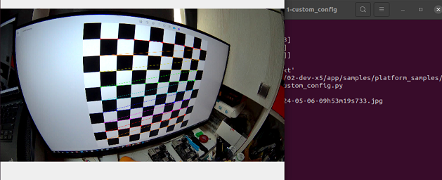
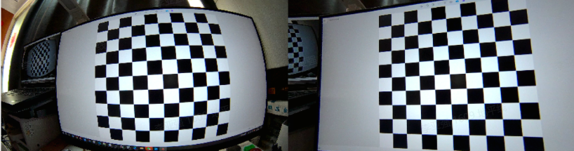
Options for generate_custom_config.py:
usage: generate_custom_config.py [-h] [-i INPUT_IMAGES_DIR] [-t TEST_IMAGE]
                                 [-o OUTPUT_FILE]

Gdc calibration and image undistortion.

optional arguments:
  -h, --help            show this help message and exit
  -i INPUT_IMAGES_DIR, --input_images_dir INPUT_IMAGES_DIR
                        Directory containing the chessboard images.
  -t TEST_IMAGE, --test_image TEST_IMAGE
                        File path of the image to be undistorted.
  -o OUTPUT_FILE, --output_file OUTPUT_FILE
                        File path for the output configuration.
3.6.2. 2-generate_bin
3.6.2.1. Overview
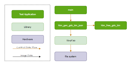
This program reads a local gdc_bin_custom_config.json configuration file and generates the corresponding gdc.bin file.
Software Architecture Description
Code Location and Directory Structure
Code location:
app/samples/platform_samples/sample_gdcDirectory structure
sample_gdc/
├── 2-generate_bin
│   ├── Makefile
│   ├── gdc_bin_custom_config.json
│   └── generate_bin.c
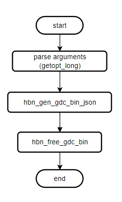
API Flow Description
3.6.2.2. Build and Deployment
Build
Enter the
sample_gdcdirectory and runmaketo compile.The output artifact is
generate_binlocated in thesample_gdc/2-generate_bindirectory.For detailed compilation methods, refer to the Build Method section.
Program Deployment
After flashing the system software image, the executable file for this sample is located on the target device at: /app/platform_samples/sample_gdc/2-generate_bin.
3.6.2.3. Run
How to Run
Run the program with ./generate_bin -h to get help information:
./generate_bin -h
genereate_bin [-c json_config_file] [-o output_file]
Program Option Descriptions
Options:
[-c json_config_file]: Specify the JSON parameter file for configuring the GDC module (optional), default is./gdc_bin_custom_config.json.[-o output_file]: Specify the output path for the GDC bin file (optional), default is./gdc.bin.
Execution Results
Run the command:
cd 2-generate_bin
chmod +x generate_bin
./generate_bin
Log output:
Gdc bin custom config: ./gdc_bin_custom_config.json
Generate gdc bin file: ./gdc.bin
Generate bin file size:10972
3.6.3. 3-gdc_static_valid
3.6.3.1. Overview
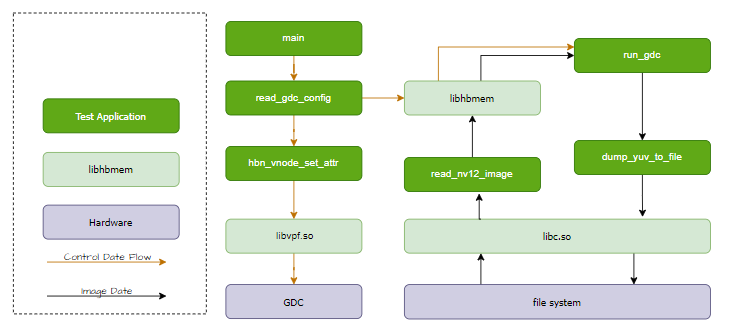
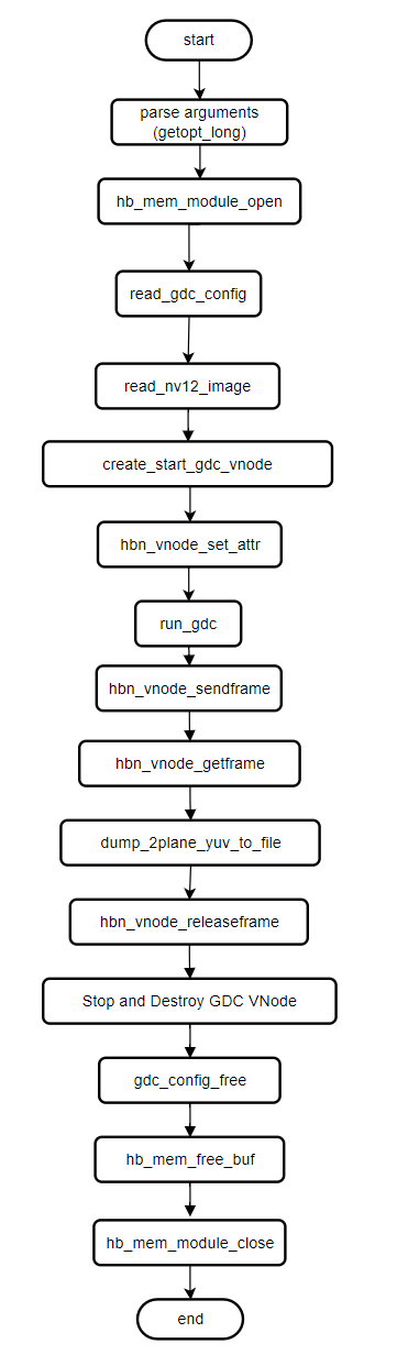
The gdc_static_valid program reads a local NV12 YUV image, sends it along with gdc.bin to GDC for transformation, and saves the result as a local NV12 format YUV image.
Software Architecture Description
Code Location and Directory Structure
Code location:
app/samples/platform_samples/sample_gdcDirectory structure
sample_gdc/
├── 3-gdc_static_valid
│   ├── Makefile
│   ├── gdc_static_valid.c
│   └── test_res
│       ├── test_image_1920x1080.jpg
│       └── test_image_1920x1080.yuv
API Flow Description
3.6.3.2. Build and Deployment
Build
Enter the
sample_gdcdirectory and runmaketo compile.The output artifact is
gdc_static_validlocated in thesample_gdc/3-gdc_static_validdirectory.For detailed compilation methods, refer to the Build Method section.
Program Deployment
After flashing the system software image, the executable file for this sample is located on the target device at: /app/platform_samples/sample_gdc/3-gdc_static_valid.
3.6.3.3. Run
How to Run
Run the program with ./gdc_static_valid to get help information:
Usage: gdc_static_valid [OPTIONS]
Options:
  c, --config <gdc_bin_file>    Specify the gdc configuration bin file.
  i, --input <input_file>       Specify the input image file.
  o, --output <output_file>     Specify the output image file.
  w, --iw <input_width>         Specify the width of the input image.
  h, --ih <input_height>        Specify the height of the input image.
  x, --ow [output_width]        Specify the width of the output image (optional).
  y, --oh [output_height]       Specify the height of the output image (optional).
  f, --feedback                 Specify feedback mode

If --ow and --oh are not specified, they will default to the input width and height, respectively.
Program Option Descriptions
Options for gdc_static_valid:
c, --config: Specify the gdc.bin configuration filei, --input: Specify the input NV12 imageo, --output: Specify the output NV12 imagew, --iw: Specify the input image width (horizontal resolution)h, --ih: Specify the input image height (vertical resolution)x, --ow: Specify the output image width (optional), defaults to input widthy, --oh: Specify the output image height (optional), defaults to input heightf, --feedback: Use feedback mode
Execution Results
Run the command to perform static image correction validation:
cd 3-gdc_static_valid
chmod +x gdc_static_valid
./gdc_static_valid -c ../2-generate_bin/gdc.bin -i test_res/test_image_1920x1080.yuv -o gdc_output_1920x1080.yuv -w 1920 -h 1080
Log output:
config file: ../2-generate_bin/gdc.bin
input image: test_res/test_image_1920x1080.yuv
output image: gdc_output_1920x1080.yuv
input:1920x1080
output:1920x1080
(read_yuvv_nv12_file):file read(test_res/test_image_1920x1080.yuv), y-size(2073600)
3.6.4. 4-gdc_stress_test
3.6.4.1. Overview
The gdc_stress_test program reads a local NV12 YUV image, sends it along with gdc.bin to GDC for transformation, and saves the result as a local NV12 format YUV image. It allows specifying the number of GDC processing iterations, records execution time, and calculates frame rate (FPS) and total processing time.
Software Architecture Description
Code Location and Directory Structure
Code location:
app/samples/platform_samples/sample_gdcDirectory structure
sample_gdc/
├── 4-gdc_stress_test
│   ├── Makefile
│   ├── gdc_1920x1080.bin
│   ├── gdc_stress_test.c
│   ├── test.sh
│   └── test_res
│       ├── test_image_1920x1080.jpg
│       └── test_image_1920x1080.yuv
API Flow Description

3.6.4.2. Build and Deployment
Build
Enter the
sample_gdcdirectory and runmaketo compile.The output artifact is
gdc_stress_testlocated in thesample_gdc/4-gdc_stress_testdirectory.For detailed compilation methods, refer to the Build Method section.
Program Deployment
After flashing the system software image, the executable file for this sample is located on the target device at: /app/platform_samples/sample_gdc/4-gdc_stress_test.
3.6.4.3. Run
How to Run
Run the program with ./gdc_stress_test to get help information:
Usage: gdc_stress_test [OPTIONS]
Options:
  c, --config <gdc_bin_file>    Specify the gdc configuration bin file.
  i, --input <input_file>       Specify the input image file.
  o, --output <output_file>     Specify the output image file.
  w, --iw <input_width>         Specify the width of the input image.
  h, --ih <input_height>        Specify the height of the input image.
  x, --ow [output_width]        Specify the width of the output image (optional).
  y, --oh [output_height]       Specify the height of the output image (optional).
  C, --Count [run count]        Specify gdc sendframe and getframe count.
  p, --p [process id]           Specify id of process.
  f, --feedback                 Specify feedback mode

If --ow and --oh are not specified, they will default to the input width and height, respectively.
Program Option Descriptions
Options for gdc_stress_test:
c, --config: Specify the gdc.bin configuration filei, --input: Specify the input NV12 imageo, --output: Specify the output NV12 imagew, --iw: Specify the input image width (horizontal resolution)h, --ih: Specify the input image height (vertical resolution)x, --ow: Specify the output image width (optional), defaults to input widthy, --oh: Specify the output image height (optional), defaults to input heightC, --Count: Specify the number of times to send frames to the GDC module.p, --p: Specify the process ID.f, --feedback: Use feedback mode.
Execution Results
Run the command:
cd 4-gdc_stress_test
chmod +x gdc_stress_test
sh test.sh
Log output:
sh test.sh
GDC vnode work mode: vflow
config file: ./gdc_1920x1080.bin
input image: ./test_res/test_image_1920x1080.yuv
output image: ./gdc_output_1920x1080.yuv
input:1920x1080
output:1920x1080
GDC vnode work mode: vflow
config file: ./gdc_1920x1080.bin
input image: ./test_res/test_image_1920x1080.yuv
output image: ./gdc_output_1920x1080.yuv
input:1920x1080
output:1920x1080
GDC vnode work mode: vflow
config file: ./gdc_1920x1080.bin
input image: ./test_res/test_image_1920x1080.yuv
output image: ./gdc_output_1920x1080.yuv
input:1920x1080
output:1920x1080
(read_yuvv_nv12_file):file read(./test_res/test_image_1920x1080.yuv), y-size(2073600)
(read_yuvv_nv12_file):file read(./test_res/test_image_1920x1080.yuv), y-size(2073600)
(read_yuvv_nv12_file):file read(./test_res/test_image_1920x1080.yuv), y-size(2073600)
gdc temp fps [process1] = 50
gdc temp fps [process3] = 50
gdc temp fps [process2] = 50
gdc temp fps [process1] = 75
gdc temp fps [process3] = 75
gdc temp fps [process2] = 75
.......
gdc temp fps [process1] = 87
gdc temp fps [process3] = 87
Gdc time consuming [process1]: 28
fps average gdc [process1] = 107
Gdc time consuming [process3]: 28
fps average gdc [process3] = 107
Gdc time consuming [process2]: 28
fps average gdc [process2] = 107
3.6.5. 5-gdc_equisolid
3.6.5.1. Overview
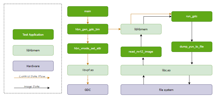
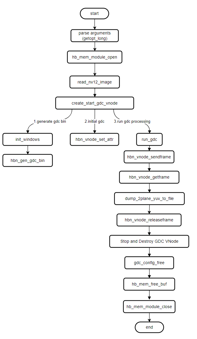
The gdc_equisolid program reads a local NV12 YUV image, sends it to GDC for (panoramic) correction processing, and saves the corrected result as a local NV12 format YUV image.
Software Architecture Description
Code Location and Directory Structure
Code location:
app/samples/platform_samples/sample_gdcDirectory structure
sample_gdc/
├── 5-gdc_equisolid
```│   ├── Makefile
│   └── gdc_equisolid.c
API Flow Description
3.6.5.2. Compilation and Deployment
Compilation
Enter the
sample_gdcdirectory and runmaketo compileThe output artifact is
gdc_equisolidlocated in thesample_gdc/5-gdc_equisoliddirectoryFor detailed compilation instructions, refer to the Compilation Method section
Program Deployment
After flashing the system software image, the executable file of this sample is located on the board at: /app/platform_samples/sample_gdc/5-gdc_equisolid.
3.6.5.3. Running
How to Run the Program
Run the program directly with ./gdc_equisolid -h to get help information:
Usage: gdc_equisolid [OPTIONS]
Options:
  i, --input <input_file>       Specify the input image file.
  o, --output <output_file>     Specify the output image file.
  w, --iw <input_width>         Specify the width of the input image.
  h, --ih <input_height>        Specify the height of the input image.
  f, --feedback                 Specify feedback mode
Program Option Description
Description of options for gdc_equisolid:
Options:
i, --input: Specify the input NV12 imageo, --output: Specify the output NV12 image (optional)w, --iw: Specify the horizontal resolution (width) of the input imageh, --ih: Specify the vertical resolution (height) of the input imagef, --feedback: Use feedback mode
Running Results
Execute the command to complete the static image (panoramic) correction verification:
cd 5-gdc_equisolid
chmod +x gdc_equisolid
./gdc_equisolid -i ../3-gdc_static_valid/test_res/test_image_1920x1080.yuv --iw 1920 --ih 1080
Runtime log:
input file: ../3-gdc_static_valid/test_res/test_image_1920x1080.yuv
output file: gdc_output_1080x1920.yuv
input:1920x1080
(read_yuvv_nv12_file):file read(../3-gdc_static_valid/test_res/test_image_1920x1080.yuv), y-size(2073600)
3.6.6. 6-gdc_transformation
3.6.6.1. Function Overview
The gdc_transformation in this document implements the GDC module to perform 180-degree linear transformation, cylindrical transformation, equidistant transformation, and trapezoidal correction with dewarping on feedback-input images.
Software Architecture Description:
The gdc_transformation program adopts a feedback workflow: it reads the original YUV file and JSON file generated by the GDC Tool from system storage as input for GDC. It relies on libgdcbin.so to calculate GDC coordinate points and saves the transformed image as a local NV12 format YUV file.
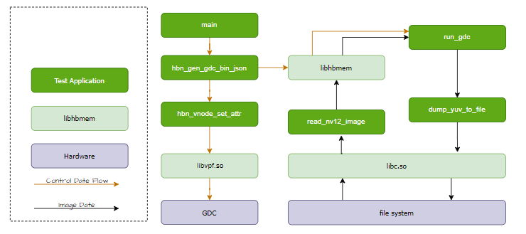
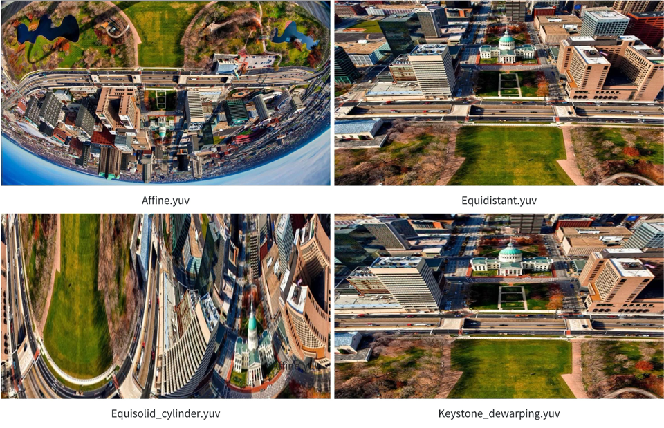
All JSON files generated by the GDC Tool are stored in the gdc_res directory. Currently, there are four JSON files in this directory, corresponding to the following transformation effects: Affine, Equisolid (cylinder), Equidistant, and Keystone + dewarping. The gdc_transformation program will generate four YUV images based on these four JSON files.
Note: The number of YUV images generated equals the number of JSON files in the gdc_res directory.
Code Location and Directory Structure
Code location:
app/samples/platform_samples/sample_gdcDirectory structure
sample_gdc/
└── 6-gdc_transformation
    ├── Makefile
    ├── gdc_res
    │   ├── Affine.json
    │   ├── Equidistant.json
    │   ├── Equisolid_cylinder.json
    │   ├── Keystone_dewarping.json
    │   └── test_building_1920x1080.yuv
    └── gdc_transformation.c
The root directory contains the Makefile. The gdc_res directory contains resource files such as JSON files and YUV images generated by the GDC Tool. The gdc_transformation.c file is the main entry point of the program.
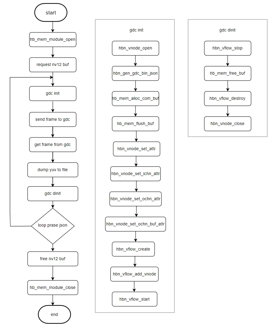
API Flow Description
Example:
3.6.6.2. Compilation and Deployment
Compilation
Enter the
sample_gdcdirectory and runmaketo compileThe output artifact is
gdc_transformationlocated in thesample_gdc/6-gdc_transformationdirectoryFor detailed compilation instructions, refer to the Compilation Method section
Program Deployment
After flashing the system software image, the executable file of this sample is located on the board at: /app/platform_samples/sample_gdc/6-gdc_transformation.
3.6.6.3. Running
How to Run the Program
Run the program directly with ./gdc_transformation to get help information:
Usage: gdc_transformation [OPTIONS]
Options:
  i, --input <input_file>       Specify the input image file.
  x, --ix <input_width>         Specify the width of the input image.
  y, --iy <input_height>        Specify the height of the input image.
Program Option Description
Description of options for gdc_transformation:
Options:
i, --input: Specify the input NV12 imagex, --ix: Specify the horizontal resolution (width) of the input imagey, --iy: Specify the vertical resolution (height) of the input image
Running Results
Execute the command to complete the static image transformation verification:
cd 6-gdc_transformation
chmod +x gdc_transformation
./gdc_transformation -i gdc_res/test_building_1920x1080.yuv --ix 1920 --iy 1080
Runtime log:
#./gdc_transformation -i gdc_res/test_building_1920x1080.yuv --ix 1920 --iy 1080
input file: gdc_res/test_building_1920x1080.yuv
input:1920x1080
(read_yuvv_nv12_file):file read(gdc_res/test_building_1920x1080.yuv), y-size(2073600)
Dump image to file(Equidistant.yuv), size(2073600) + size1(1036800) succeeded
Dump image to file(Keystone_dewarping.yuv), size(2073600) + size1(1036800) succeeded
Dump image to file(Affine.yuv), size(2073600) + size1(1036800) succeeded
Dump image to file(Equisolid_cylinder.yuv), size(2073600) + size1(1036800) succeeded
Description of options for gdc_transformation:
#./gdc_transformation -h
Usage: gdc_transformation [OPTIONS]
Options:
  i, --input <input_file>       Specify the input image file.
  x, --ix <input_width>         Specify the width of the input image.
  y, --iy <input_height>        Specify the height of the input image.
Running Results Description
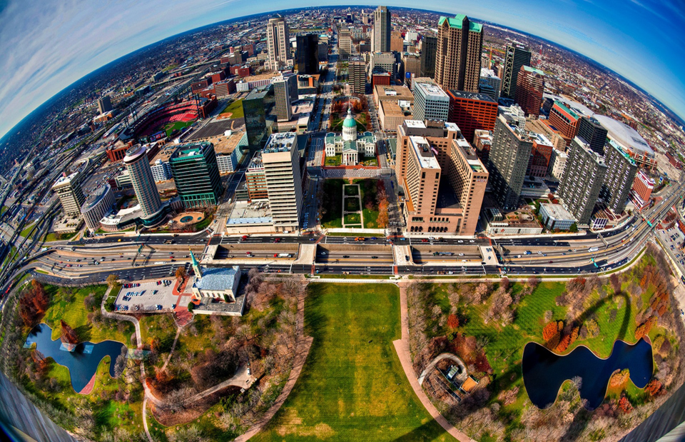
The original image is shown below:
After parsing and transforming according to each JSON file, four processed NV12-format YUV images are generated, as shown below: