5.10.4. GDC Tool
5.10.4.1. Introduction to GDC Tool
GDC Tool is a tool for simulating processing effects on PCs. Users can prepare images in JPG format, load them into the GDC Tool for offline correction, and then directly save BIN files for hardware correction, or save a layout.json file to generate a BIN file for hardware correction.
Launching GDC Tool
1. Windows Environment
Environment Setup: Requires Node.js. Reference download: https://nodejs.cn/download/.
Tool Acquisition: Download the GDC tool (gdc-tool-xxxx-windows) from the release package, located at: /X5_LNX_SDK/LNX6.1.83_PLx_Vx.x.xx/software_tools/gdc_tools/.
Install Dependencies: In the Windows command line, navigate to the GDC tool directory (e.g., gdc-tool-gui-xxxx-windows), and execute npm install express.
Launch Application: In the Windows command line, navigate to the GDC tool directory (e.g., gdc-tool-gui-xxxx-windows), and execute node.exe app.js. Use Chrome browser to access http://localhost:3000/.
2. Unix Environment
Environment Setup: Mac: brew install node.
Install Dependencies: Run npm install -production in the directory.
Launch Application: Run node app.js, then open a web browser and go to http://localhost:3000/.
3. Start Simulation
Using the GDC Tool generally involves the following steps:
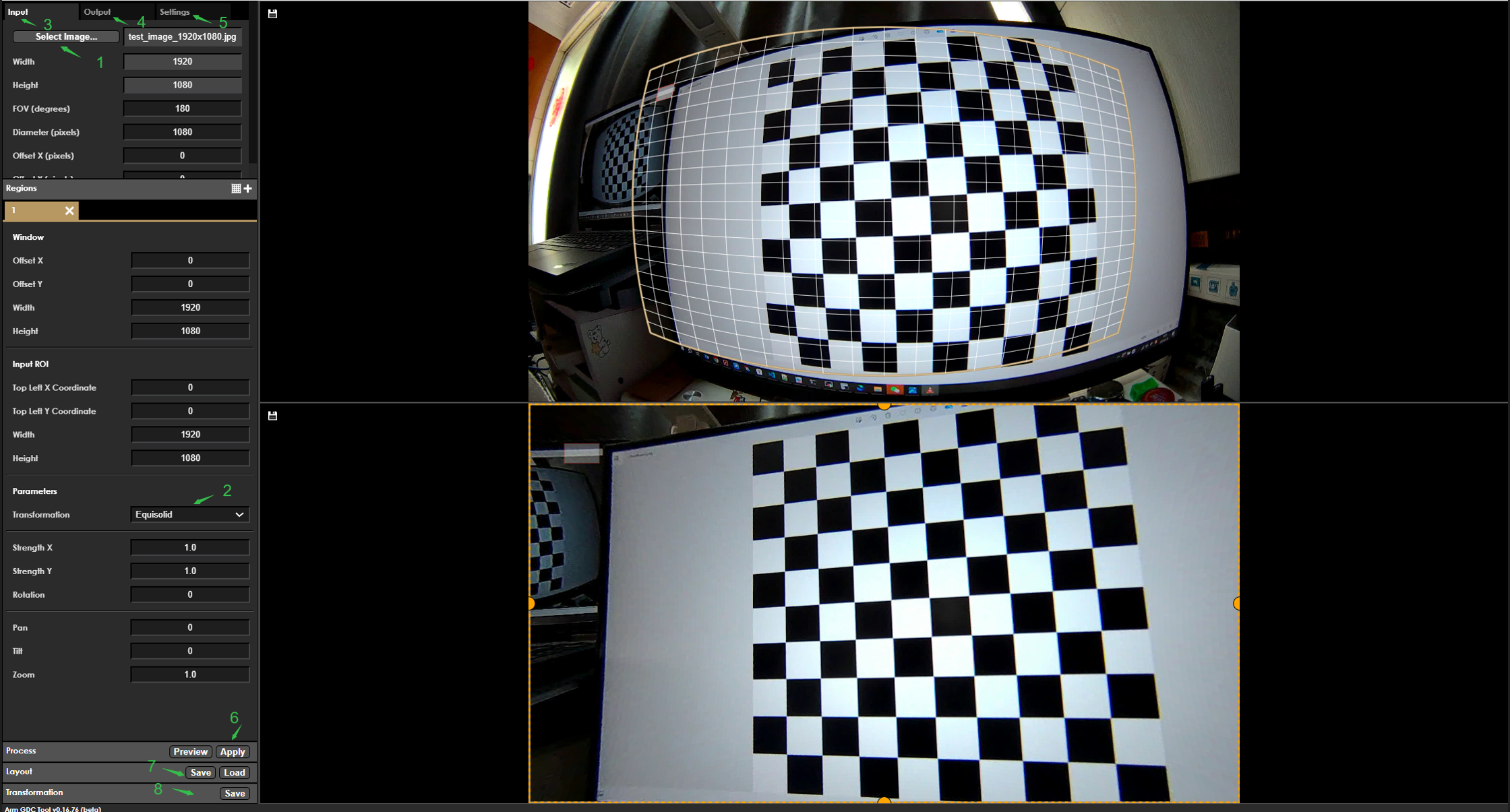
The green arrows in the above figure correspond to the steps listed below.
After successfully logging into the web interface, upload the prepared image captured by the sensor. Before uploading, convert the captured YUV image to JPG format.
Prepare JPG Image: Use ffmpeg to convert the YUV file obtained from the sensor into a JPG image for upload. Example command:
ffmpeg -s 1920x1080 -pix_fmt yuv420p -i handle_100197_isp_chn0_1920x1080_stride_1920_frameid_0_ts_2411352368066.yuv output.jpg
Confirm the transformation mode based on the use case. Set Transformation to the corresponding mode. If using the Custom mode, prepare and upload the GDC calibration parameter file as well.
Configure GDC parameter information according to the transformation mode, setting Input in the diagram. For details, see section Transformation Mode Parameter Description.
Configure GDC parameter information according to the transformation mode, setting Output in the diagram. For details, see section Transformation Mode Parameter Description.
Configure GDC parameter information according to the transformation mode, setting Settings in the diagram. For details, see section Transformation Mode Parameter Description.
After successfully configuring the GDC parameters, click Preview to view the result and confirm whether it meets expectations.
After confirming the simulation result meets expectations, export the
layout.jsonfile for use. Usage instructions can be found in the GDC sample code section sample_gdc.After confirming the simulation result meets expectations, export the BIN file for use. Usage instructions can be found in the GDC sample code section sample_gdc.
Transformation Modes in GDC Tool
GDC Tool provides six transformation modes: Affine, Equisolid, Equisolid (cylinder), Equidistant, Custom, and Keystone+dewarping. These modes correspond to the transformation modes in software, as described in the transformation_t section of the GDC Bin API documentation.
The table below describes the purpose of each transformation.
| Transformation Mode | Purpose |
|---|---|
| Affine | A linear transformation that provides simple image rotation without distortion correction |
| Equisolid | Panoramic transformation with maximum grid coverage |
| Equisolid (cylinder) | Cylindrical transformation |
| Equidistant | Equidistant transformation where output distances are uniformly spaced |
| Keystone + dewarping | Compared to Equidistant, dewarp_keystone adds two parameters: trapezoid_left_angle and trapezoid_right_angle. By default, both are 90 degrees, producing the same effect as Equidistant |
| Custom | User-defined transformation |
All transformation types have the following three common parameters: Pan, Tilt, Zoom (example: equidistant transformation with input/output resolution 1280x720):
In the following output images, the blue rectangle indicates only the specific parameter is set to that value, while all other parameters in the transformation remain at their default values.
Pan
Horizontal offset (-1280, +1280): Shifts the transformation grid by the given number of pixels horizontally. As shown below:

Tilt
Vertical offset (-720, +720): Shifts the transformation grid by the given number of pixels vertically. As shown below:

Zoom
Scale factor (0, +∞): Scales the transformation output by the provided factor; (0, 1) means values greater than 0 and less than 1. As shown below:

Affine
【Function Description】
Provides linear transformation.
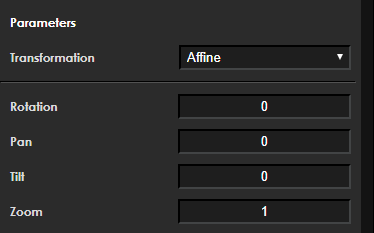
【Member Description】
| Member | Meaning |
|---|---|
| int32_t pan | default 0, no change |
| int32_t tilt | default 0, no change |
| zoom | scale transformation output by provided factor |
| double angle (rotation) | 0/90/180/270 |
Equisolid
【Function Description】
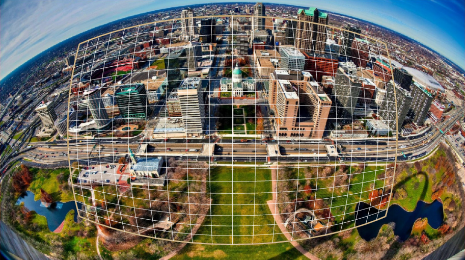
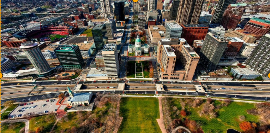
This transformation provides equisolid (panoramic) correction and displays the result as a planar projection.
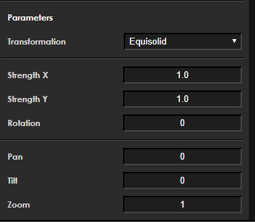
【Member Description】
| Member | Meaning |
|---|---|
| int32_t pan | default 0, no change |
| int32_t tilt | default 0, no change |
| zoom | scale transformation output by provided factor |
| double strength | transformation strength along the X-axis (non-negative) |
| double strengthY | transformation strength along the Y-axis (non-negative) |
| double angle (rotation) | 0/90/180/270 |
Strength X debugging effect: transformation strength along the X-axis, range (0, +∞). As shown below:

Strength Y debugging effect: transformation strength along the Y-axis, range (0, +∞). As shown below:

Rotation debugging effect: value range (-180, 180). As shown below:

Equisolid (cylinder)
【Function Description】
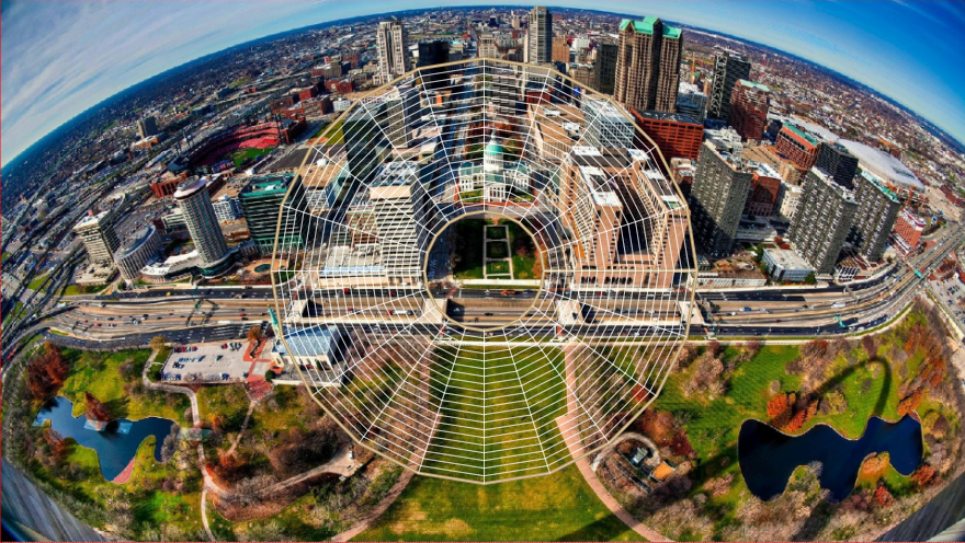
This transformation provides equisolid correction for projecting the result image onto a cylindrical panoramic view from a full fisheye frame.
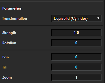
【Member Description】
| Member | Meaning |
|---|---|
| int32_t pan | default 0, no change |
| int32_t tilt | default 0, no change |
| zoom | scale transformation output by provided factor |
| strength | transformation strength |
| double angle (rotation) | 0/90/180/270 |
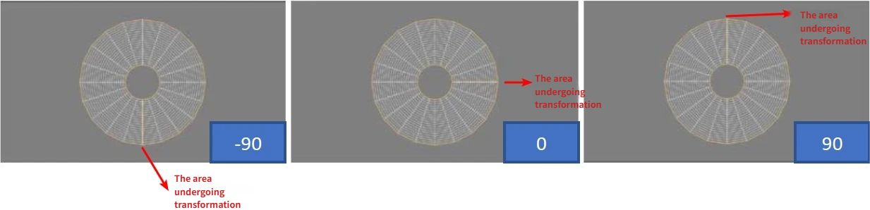
Strength debugging effect: transformation strength (0, +∞). As shown below:

Rotation debugging effect: value range (-180, +180). As shown below:
Equidistant
【Function Description】
The equidistant transformation includes many parameters that allow it to project to a variety of target planes. This gives users more freedom to select the desired region of the fisheye frame to transform.
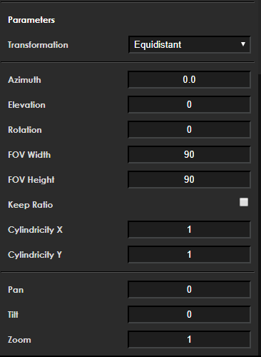
【Member Description】
| Member | Meaning |
|---|---|
| int32_t pan | Horizontal offset of the transformation grid by given number of pixels |
| int32_t tilt | Vertical offset of the transformation grid by given number of pixels |
| zoom | Scale transformation output by provided factor |
| double angle(rotation) | Rotation angle of the image |
| double elevation | Defines the elevation angle of the projection axis, range 0 to 90 |
| double azimuth | Defines the azimuth angle of the projection axis. If elevation is 0, azimuth has no visible effect |
| int32_t keep_ratio | When "keep ratio" is enabled, the FOV height parameter is ignored and automatically calculated to maintain equal stretch intensity in horizontal and vertical directions |
| double FOV_h | Describes the size of the output field of view in the horizontal dimension (in degrees). Valid range: 0 to 180 |
| double FOV_w | Describes the size of the output field of view in the vertical dimension (in degrees). Valid range: 0 to 180 |
| double cylindricity_y | Describes the sphericity of the target projection along the Y-axis. Value from 0 to 1, where 1 is spherical. If set to 1 and cylindricity_x is 0, projection forms a cylinder along Y-axis |
| double cylindricity_x | Describes the sphericity of the target projection along the X-axis. Value from 0 to 1, where 1 is spherical. If set to 1 and cylindricity_y is 0, projection forms a cylinder along X-axis |
The width of input and output dimensions should be aligned to 16 pixels.
Normal field of view is approximately 90 degrees. For transformations with cylindricity (see below) equal to "0", FOV width and height values of 180 will cause infinite image stretching.
If both cylindricity_x and cylindricity_y are set to 1, the projection will be spherical. If both are 0, the transformation will be rectangular.
Elevation debugging effect:

Azimuth debugging effect:

Rotation debugging effect:

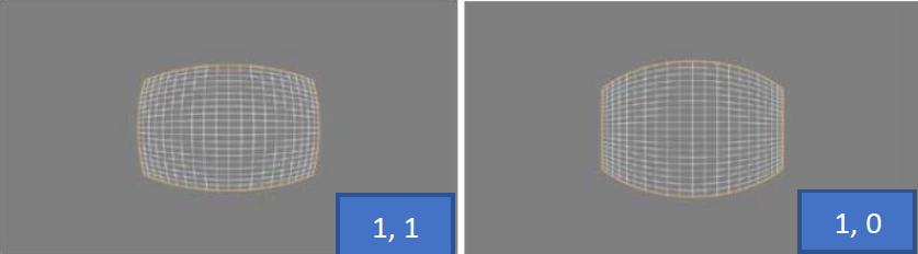
Cylindricity X debugging effect:
Describes the degree of sphericity of the target projection along the X-axis. Value range: 0 to 1, where 1 is spherical. If set to 1 and cylindricity Y is 0, the projection forms a cylinder along the X-axis. As shown below:
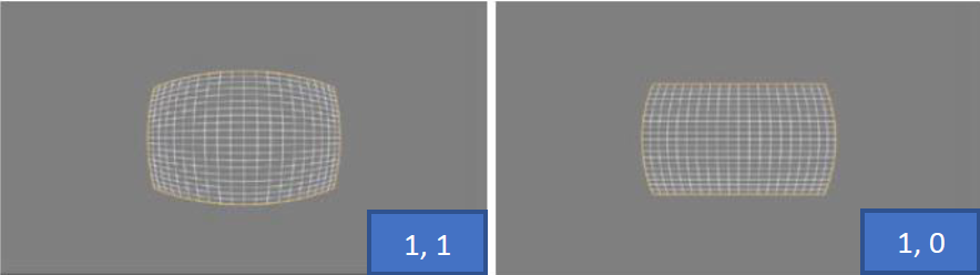
Cylindricity Y debugging effect:
Describes the degree of sphericity of the target projection along the Y-axis. Value range: 0 to 1, where 1 is spherical. If set to 1 and cylindricity X is 0, the projection forms a cylinder along the Y-axis. As shown below:
Custom
【Function Description】
With the Custom transformation, each polygon in the input image is transformed into a square. In other words, any four adjacent input points of any shape become a square after transformation, as shown below. However, the shape and position of the polygons will change after transformation.
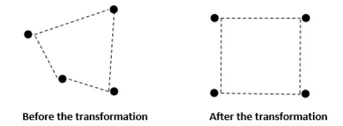
They are used to create transformations that cannot be described by any provided transformation. To correct arbitrary distortions, a special calibration file must be provided to the GDC tool. As shown below:
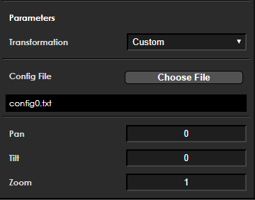
【Member Description】
| Member | Meaning |
|---|---|
| int32_t pan | Horizontal offset of the transformation grid by given number of pixels |
| int32_t tilt | Vertical offset of the transformation grid by given number of pixels |
| zoom | Scale transformation output by provided factor |
| char custom_file[128] | Sampling point file name |
| custom_tranformation_t custom | Parsed custom transformation structure |
Sampling Point File Explanation
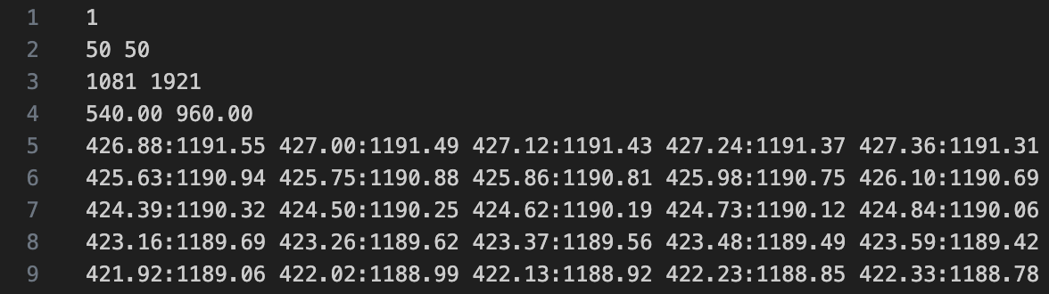
Rules for sampling point files:
The first line enables full tile in pixel calculation: 1 for enable, 0 for disable.
The second line specifies the number of pixels to skip if full tile is enabled; these values must be greater than 0. Smaller numbers result in slower libgdc performance (slower performance means the BIN file generated by libgdc is larger and takes longer to generate).
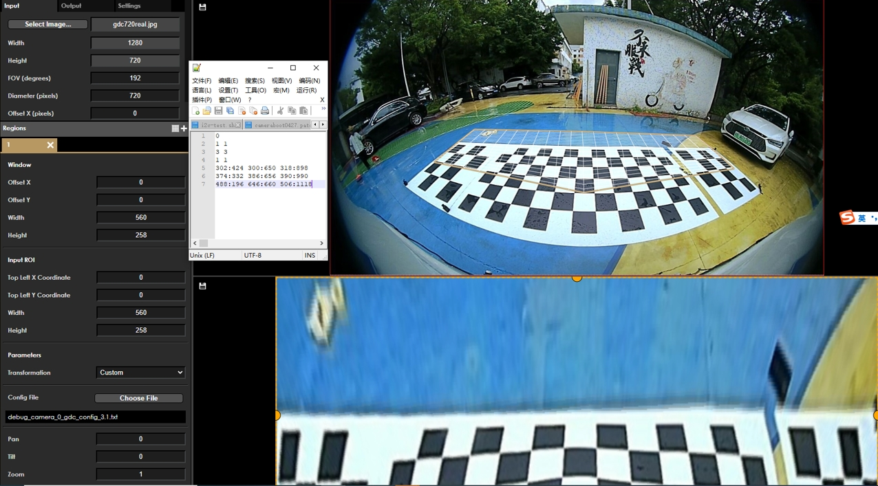
The third line specifies the number of sampling points in vertical and horizontal directions. The first value Y = 1081 means there are 1081 sampling points vertically, and the second value X = 1921 means there are 1921 sampling points horizontally.
The fourth line specifies the center point of the selected region, typically (Y-1)/2, (X-1)/2.
Sampling points must be non-negative integers or floats, and adjacent rows must not have duplicate sampling points.
e.g. The image below shows a partial data extract. Rows 5 to 9 contain coordinate values of sampling points in the source image, formatted as Y:X. In this example, there are 1081x1921 sampling points.
Since sampling points must be equidistant, the output image resolution depends on the number of sampling points.
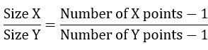
e.g. Output image Width = 100, Height calculated as 340. Calculation: 100/height = (96-1)/(324-1)
The image below shows a simpler example of 3x3 coordinate point transformation:
Downsampling
The skip_point function determines whether the current point can be skipped, achieving downsampling.
Note: width and height are actual width and height plus 1: width + 1, height + 1
uint32_t skip_point(uint32_t width, uint32_t height, uint32_t x, uint32_t y)
{
    const uint32_t sample_points = 32;
    uint32_t step_x = floor((ceil(((float)width) / (sample_points - 4)) + 1) / 2.) * 2;
    uint32_t step_y = floor((ceil(((float)height) / (sample_points - 4)) + 1) / 2.) * 2;
    uint32_t grid_fit_x = ((x % step_x == step_x / 2) || (x - 1) % step_x == step_x / 2 ||
             (x % step_x == 0) || (x - 1) % step_x == 0 || x == 0 || x == 1);
    uint32_t grid_fit_y = ((y % step_y == step_y / 2) || (y - 1) % step_y == step_y / 2 ||
             (y % step_y == 0) || (y - 1) % step_y == 0 || y == 0 || y == 1);

    return !((grid_fit_x && grid_fit_y) || (x >= width - 2) || (y >= height - 2));
}
Example usage: downsampling for a 608x600 point grid:
int row_start = 0, row_end = 601;
int col_start = 0, col_end = 609;
int necessary_point = 1;

  for (int i = row_start; i < row_end; i++) {
    for (int j = col_start; j < col_end; j++) {
      int x = j - col_start;
      int y = i - row_start;

      necessary_point = skip_point(col_end - col_start, row_end - row_start, x, y);
      if (necessary_point) {
            //idx_x, idx_y are sampling point coordinates
            file_out << idx_y[i * 609 + j] << ":" << idx_x[i * 609 + j] << " "; // essential point, write to sampling file
      } else {
            file_out << 0.0 << ":" << 0.0 << " ";   // non-essential point, write 0 to sampling file, effectively skipping
      }
    }
    file_out << std::endl;
  }
Keystone+dewarping
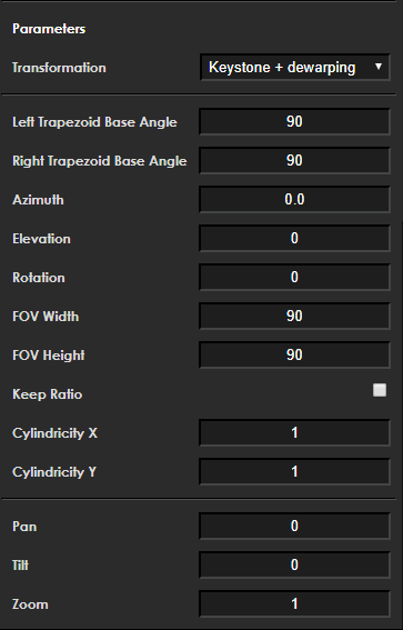
【Function Description】
【Member Description】
| Member | Meaning |
|---|---|
| int32_t pan | Horizontal offset of the transformation grid by given number of pixels |
| int32_t tilt | Vertical offset of the transformation grid by given number of pixels |
| zoom | Scale transformation output by provided factor |
| double angle(rotation) | Rotation angle of the image |
| double elevation | Defines the elevation angle of the projection axis, range 0 to 90 |
| double azimuth | Defines the azimuth angle of the projection axis. If elevation is 0, azimuth has no visible effect |
| int32_t keep_ratio | When "keep ratio" is enabled, FOV height parameter is ignored and automatically calculated to maintain equal stretch intensity |
| double FOV_h | Describes the size of the output field of view in the horizontal dimension (in degrees). Valid range: 0 to 180 |
| double FOV_w | Describes the size of the output field of view in the vertical dimension (in degrees). Valid range: 0 to 180 |
| double cylindricity_y | Describes the sphericity of the target projection along the Y-axis (range 0 to 1). 1 means spherical. If set to 1 and cylindricity_x is 0, projection forms a cylinder along Y-axis |
| double cylindricity_x | Describes the sphericity of the target projection along the X-axis (range 0 to 1). 1 means spherical. If set to 1 and cylindricity_y is 0, projection forms a cylinder along X-axis |
| double trapezoid_left_angle | Default 90; range 0.1 to 90. In the transformation grid, the angle of the left boundary relative to the bottom boundary, see actual effect |
| double trapezoid_right_angle | Default 90; range 0.1 to 90. In the transformation grid, the angle of the right boundary relative to the bottom boundary, see actual effect |
Transformation Mode Parameter Description
Configuration files can be generated by the GDC Tool and saved as layout.json. Different transformation modes have different parameters. Taking Custom and Keystone+dewarping modes as examples, the configuration parameters are explained below.
Keystone+dewarping Mode
{
  "inputRes": [
    1920, -- Width of input image
    1080 -- Height of input image
  ],
  "param": {
    "fov": 180, -- Field of view of input image
    "diameter": 1080, -- Diameter of input image, controls overall size of transformation grid
    "offsetX": 0, -- Horizontal offset of transformation grid
    "offsetY": 0 -- Vertical offset of transformation grid
  },
  "outputRes": [
    1920, -- Width of output image
    1080 -- Height of output image
  ],
  "transformations": [
    {
      "transformation": "Dewarp_keystone", -- Transformation mode
      "position": [ -- ROI setting of output image
        0, -- Horizontal offset of output image ROI
        0, -- Vertical offset of output image ROI
        1920, -- Width of output image ROI
        1080 -- Height of output image ROI
      ],
      "param": {
        "left_base_angle": 90, -- Default 90; range 0.1 to 90; angle of left boundary relative to bottom boundary in transformation grid
        "right_base_angle": 90, -- Default 90; range 0.1 to 90; angle of right boundary relative to bottom boundary in transformation grid
        "azimuth": 90, -- Azimuth angle of projection axis. If elevation is 0, azimuth has no visible effect
        "elevation": 0, -- Elevation angle of projection axis, range 0 to 90
        "rotation": 0, -- Rotation angle of output image
        "fovWidth": 90, -- Size of output field of view in horizontal dimension (in degrees). Larger values make the transformation grid wider horizontally, valid range 0 to 180
        "fovHeight": 90, -- Size of output field of view in vertical dimension (in degrees). Larger values make the transformation grid taller vertically, valid range 0 to 180
        "keepRatio": 0, -- When "keep ratio" is 1, fovHeight is ignored and automatically calculated to maintain equal stretch intensity in both directions
        "cylindricityX": 1, -- Sphericity of target projection along X-axis. Range 0 to 1, 1 is spherical. If set to 1 and cylindricityY is 0, projection forms a cylinder along X-axis.
        "cylindricityY": 1 -- Sphericity of target projection along Y-axis. Range 0 to 1, 1 is spherical. If set to 1 and cylindricityX is 0, projection forms a cylinder along Y-axis.
      },
      "ptz": [
        0, -- pan parameter
        0, -- tilt parameter
        1 -- zoom parameter
      ],
      "roi": { -- ROI setting of input image
        "x": 0, -- Horizontal offset of input image ROI
        "y": 0, -- Vertical offset of input image ROI
        "w": 1920, -- Width of input image ROI
        "h": 1080 -- Height of input image ROI
      }
    }
  ],
  "mode": "semiplanar420", -- Processing format setting
  "eccMode": "eccDisabled", -- ECC processing mode
  "colourspace": "yuv" -- Data format being processed
}
Custom Mode
{
  "inputRes": [
    1280, -- Width of input image
    720 -- Height of input image
  ],
  "param": {
    "fov": 192, -- Field of view of input image
    "diameter": 720, -- Diameter of input image, controls overall size of transformation grid
    "offsetX": 0, -- Horizontal offset of transformation grid
    "offsetY": 0 -- Vertical offset of transformation grid
  },
  "outputRes": [
    560, -- Width of output image
    258 -- Height of output image
  ],
  "transformations": [
    {
      "transformation": "Custom", -- Transformation mode
      "position": [ -- ROI setting of output image
        0, -- Horizontal offset of output image ROI
        0, -- Vertical offset of output image ROI
        560, -- Width of output image ROI, must be ≤ outputRes width
        258 -- Height of output image ROI, must be ≤ outputRes height
      ],
      "ptz": [
        0, -- pan parameter
        0, -- tilt parameter
        1 -- zoom parameter
      ],
      "roi": { -- Invalid in Custom mode
        "x": 0, -- Invalid in Custom mode
        "y": 0, -- Invalid in Custom mode
        "w": 0, -- Invalid in Custom mode
        "h": 0 -- Invalid in Custom mode
      },
      "param": {
        "customTransformation": "/path_to/camera_0_gdc.txt" -- Path to coordinate file on device
      }
    }
  ],
  "mode": "semiplanar420", -- Processing format setting
  "eccMode": "eccDisabled", -- ECC processing mode
  "colourspace": "yuv" -- Data format being processed
}
1. ECC mode should always be set to "eccDisabled". Optional ECC mode can be enabled but has no practical effect.
2. When parameters are decimal, ensure precision to at least 8 decimal places after floating-point calculation, otherwise generated BIN files may differ.
3. When filling data structures or JSON, include all items shown in mode examples.
4. In non-Custom modes, the roi parameter in the configuration file represents the input image's ROI.
5. The position parameter in the configuration file represents the output image's ROI.
Affine
Configuration file content:
{
   "inputRes": [
       1920,
       1080
   ],
   "param": {
       "fov": 160,
       "diameter": 1080,
       "offsetX": 0,
       "offsetY": 0
``````json
   },
   "outputRes": [
       1920,
       1080
   ],
   "transformations": [
       {
           "transformation": "Affine",
           "position": [
               0,
               0,
               1920,
               1080
           ],
           "param": {
               "rotation": 0
           },
           "ptz": [
               0,
               0,
               1
           ],
           "roi": {
               "x": 0,
               "y": 0,
               "w": 1920,
               "h": 1080
           }
       }
   ],
   "mode": "semiplanar420",
   "eccMode": "eccDisabled",
   "colourspace": "yuv"
}
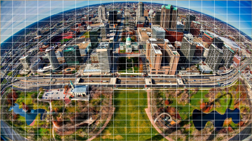
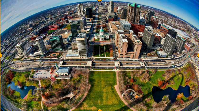
Input image with transformation grid:
Output image:
Equisolid
Configuration file content:
{
   "inputRes": [
       1920,
       1080
   ],
   "param": {
       "fov": 160,
       "diameter": 1080,
       "offsetX": 0,
       "offsetY": 0
   },
   "outputRes": [
       1920,
       1080
   ],
   "transformations": [
       {
           "transformation": "Panoramic",
           "position": [
               0,
               0,
               1920,
               1080
           ],
           "param": {
               "strength": 1,
               "strengthY": 1,
               "rotation": 0
           },
           "ptz": [
               0,
               0,
               1
           ],
           "roi": {
               "x": 0,
               "y": 0,
               "w": 1920,
               "h": 1080
           }
       }
   ],
   "mode": "semiplanar420",
   "eccMode": "eccDisabled",
   "colourspace": "yuv"
}
Input image with transformation grid:
Output image:
Equisolid(cylinder)
Configuration file content:
{
   "inputRes": [
       1920,
       1080
   ],
   "param": {
       "fov": 160,
       "diameter": 1080,
       "offsetX": 0,
       "offsetY": 0
   },
   "outputRes": [
       1920,
       1080
   ],
   "transformations": [
       {
           "transformation": "Stereographic",
           "position": [
               0,
               0,
               1920,
               1080
           ],
           "param": {
               "strength": 1,
               "rotation": 0
           },
           "ptz": [
               0,
               0,
               1
           ],
           "roi": {
               "x": 0,
               "y": 0,
               "w": 1920,
               "h": 1080
           }
       }
   ],
   "mode": "semiplanar420",
   "eccMode": "eccDisabled",
   "colourspace": "yuv"
}
Input image with transformation grid:
Output image:
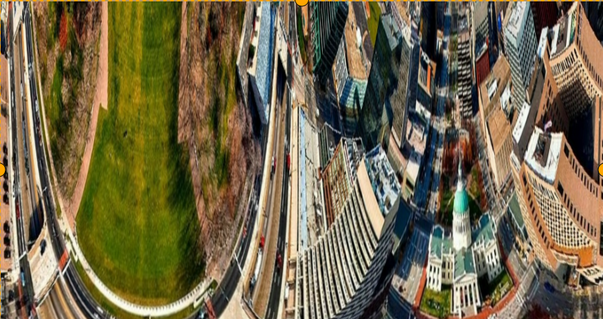
Equidistant
Configuration file content:
{
   "inputRes": [
       1920,
       1080
   ],
   "param": {
       "fov": 160,
       "diameter": 1080,
       "offsetX": 0,
       "offsetY": 0
   },
   "outputRes": [
       1920,
       1080
   ],
   "transformations": [
       {
           "transformation": "Universal",
           "position": [
               0,
               0,
               1920,
               1080
           ],
           "param": {
               "azimuth": 0,
               "elevation": 0,
               "rotation": 0,
               "fovWidth": 90,
               "fovHeight": 90,
               "keepRatio": 0,
               "cylindricityX": 1,
               "cylindricityY": 1
           },
           "ptz": [
               0,
               0,
               1
           ],
           "roi": {
               "x": 0,
               "y": 0,
               "w": 1920,
               "h": 1080
           }
       }
   ],
   "mode": "semiplanar420",
   "eccMode": "eccDisabled",
   "colourspace": "yuv"
}
Input image with transformation grid:
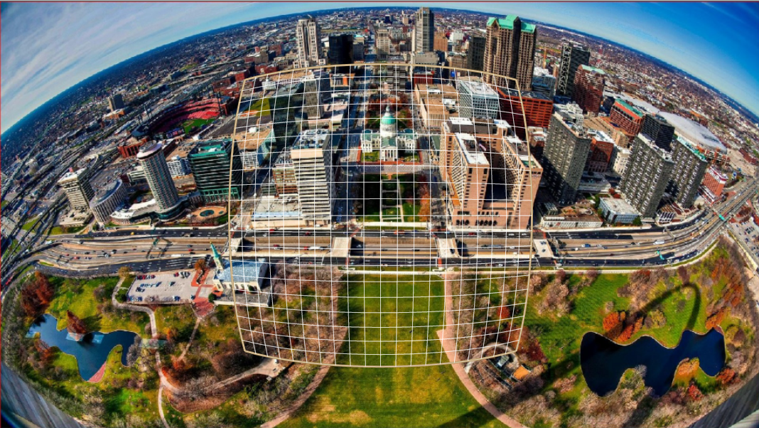
Output image:
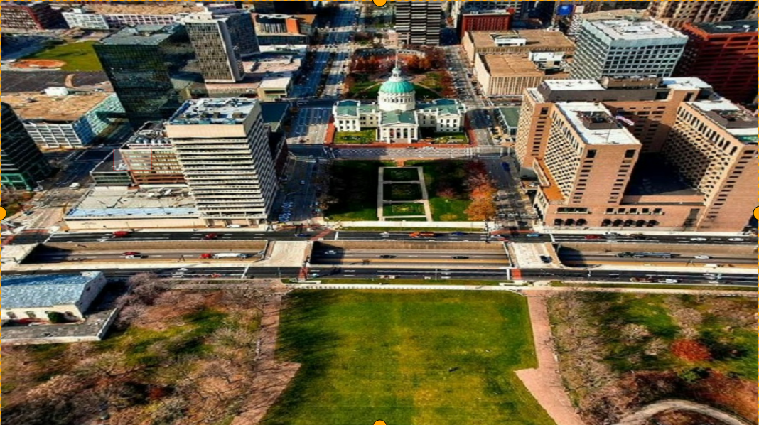
Custom
Input 1280x720, output 560x258. Configuration file content:
{
   "inputRes": [
       1280,
       720
   ],
   "param": {
       "fov": 192,
       "diameter": 720,
       "offsetX": 0,
       "offsetY": 0
   },
   "outputRes": [
       560,
       258
   ],
   "transformations": [
       {
           "transformation": "Custom",
           "position": [
               0,
               0,
               560,
               258
           ],
           "ptz": [
               0,
               0,
               1
           ],
           "roi": {
               "x": 0,
               "y": 0,
               "w": 1280,
               "h": 720
           },
           "param": {
               "customTransformation": "/path_to/camera_0_gdc_config_3.1.txt"
           }
       }
   ],
   "mode": "semiplanar420",
   "eccMode": "eccDisabled",
   "colourspace": "yuv"
}
Input image with transformation grid:
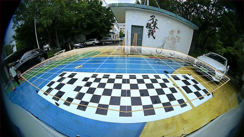
Output image:
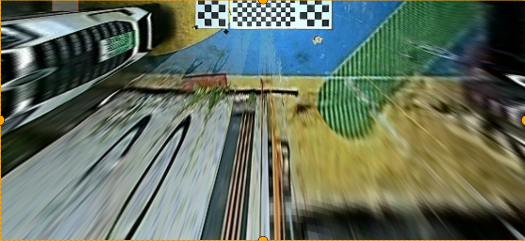
Keystone+dewarping
Configuration file content:
{
   "inputRes": [
       1920,
       1080
   ],
   "param": {
       "fov": 180,
       "diameter": 1080,
       "offsetX": 0,
       "offsetY": 0
   },
   "outputRes": [
       1920,
       1080
   ],
   "transformations": [
       {
           "transformation": "Dewarp_keystone",
           "position": [
               0,
               0,
               1920,
               1080
           ],
           "param": {
               "left_base_angle": 90,
               "right_base_angle": 90,
               "azimuth": 0,
               "elevation": 0,
               "rotation": 0,
               "fovWidth": 90,
               "fovHeight": 90,
               "keepRatio": 0,
               "cylindricityX": 1,
               "cylindricityY": 1
           },
           "ptz": [
               0,
               0,
               1
           ],
           "roi": {
               "x": 0,
               "y": 0,
               "w": 1920,
               "h": 1080
           }
       }
   ],
   "mode": "semiplanar420",
   "eccMode": "eccDisabled",
   "colourspace": "yuv"
}
Input image with transformation grid:
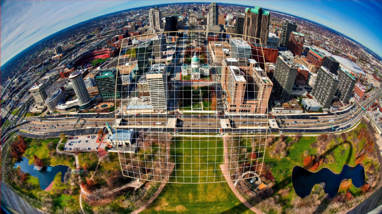
Output image: