5.1. System Overview
5.1.1. Document Usage Guide
5.1.1.1. Document Structure
Section 1: Overall description of the multimedia system
Section 2: Core software framework of the multimedia system, HBN (currently some modules in the multimedia system are not included in the HBN framework, which will be described in detail later)
Section 3: Debugging methods for the multimedia system
Sections 4–14: Detailed introduction to each individual module, including basic information, usage methods, and precautions
Section 15: Image quality tuning methods
5.1.1.2. How to Use This Document
Understand the overall structure and core framework of the multimedia system
Read Section 1 of the multimedia chapter thoroughly to understand the components of the multimedia system (including Sections 4–12 of the multimedia chapter) and the relationships among them
Read Section 2 of the multimedia chapter thoroughly to understand the core software framework HBN of the multimedia system
Browse Section 3 of the multimedia chapter to learn about the available debugging methods for the multimedia system, so that when encountering issues during later usage, you will know what tools are available for debugging
Combine with the demos in the Sample Code section to gradually understand the modules in Sections 4–14 of the multimedia chapter. At this point, you should be able to build a camera capture and processing pipeline
Follow Section 15 of the multimedia chapter to tune image quality
5.1.2. General Overview
The multimedia system integrates multiple hardware acceleration units, allowing the CPU to focus on its strengths: running the operating system and handling business logic.
Meanwhile, the system provides simple and flexible APIs for efficiently connecting and coordinating the work of various modules. The following introduces the system from both hardware and software perspectives:
Hardware aspect: Detailed explanation of the composition of hardware modules and the data interaction mechanisms between hardware units.
Software aspect: Analysis of software API design and functionality, and explanation of how to use APIs to achieve efficient data collaboration between different hardware units.
5.1.3. Hardware Aspect
5.1.3.1. Components
| Module | Full Name | Description |
|---|---|---|
| VIN | Video Input | Software concept, includes MIPI, SIF; receives single or multiple Camera sensor data, directly sends downstream to ISP or writes to DDR |
| SIF | Sensor Interface | Interfaces with MIPI, forwards data frames received via MIPI to downstream ISP or directly writes to DDR |
| ISP | Image Signal Processor | Image signal processor |
| VSE | Video Scaler | Image cropping, scaling, color space conversion |
| OSD | On Screen Display | Video image overlay display |
| GDC | Geometrical Distortion Correction | Geometric distortion correction |
| VPU | Video Processing Unit | Video processing unit, performs video encoding/decoding functions, supports H.264/H.265 |
| JPU | JPEG Processing Unit | JPEG image processing unit, performs encoding/decoding of JPEG and MJPEG |
| 2DGPU | 2D Graphics Processing Unit | 2D image acceleration unit, provides functions such as bit-block transfer, rectangle fill and clear, Alpha blending, rotation, cropping, and color space conversion |
| 3DGPU | 3D Graphics Processing Unit | Acceleration unit for 3D image rendering |
| Display | Video Display Unit | Video display module, provides layering, rotation, etc., supports BT1120, HDMI, MIPI DSI interfaces |
5.1.3.2. Data Interaction
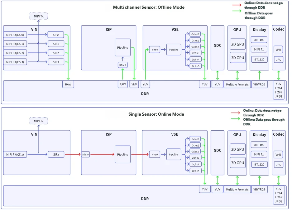
The X5 chip has dedicated data channels built-in that can directly connect the VIN, ISP, and VSE modules, enabling high-speed direct transmission of video data without reading from or writing to DDR, thus saving DDR bandwidth and significantly improving performance.
However, since the hardware resources of ISP and VSE are singular, when multiple Camera Sensors are connected, processing must be done through time-division multiplexing, requiring video data to be cached via DDR.
Depending on whether data transfer relies on DDR buffering, the data interaction between hardware acceleration units can be divided into two modes:
Offline Mode (shown as green arrows in the diagram): Data is transferred via DDR. The upstream module writes data to DDR, and the downstream module reads from DDR. This mode supports scenarios with multiple Camera Sensors.
Online Mode (shown as red arrows in the diagram): Data is directly passed from the upstream module to the downstream module without reading from or writing to DDR, significantly enhancing performance. However, this mode is only applicable to single Camera Sensor scenarios.
Note: In multi-camera sensor scenarios, ISP to VSE supports online processing, and it is recommended to use online mode (effectively reducing DDR bandwidth).
The following diagram illustrates two usage scenarios: multiple Camera Sensors and single Camera Sensor:
Summary:
VIN: Includes 4 MIPI RX and 4 SIFsMIPI RX: Connects to one MIPI interface Camera Sensor
SIF: Corresponds one-to-one with MIPI interface, forwards data frames received via MIPI to downstream ISP or directly writes to DDR
ISP: Has 4 input ports, supports connection with 4 SIFs. Since ISP has only one hardware Pipeline, when multiple Camera Sensors are connected, ISP writes data to DDR and time-shares the PipelineIn single Camera Sensor scenarios, the connection from VIN to ISP: Online mode is preferred; Offline mode is also supported
In multiple Camera Sensor scenarios, the connection from VIN to ISP: Offline mode is preferred;
Note: When an HDR sensor is connected, the VIN-ISP connection must use online mode. Since online mode exclusively occupies the ISP resource, only 1 stream is supported.
VSE: Has only one input port and one hardware unit, supports 6 output channels, each channel supports different scaling and cropping sizes, supports OSD functionality to overlay text or color blocks on imagesIn single Camera Sensor scenarios, the connection from ISP to VSE: Online mode is preferred; Offline mode is supported
In multiple Camera Sensor scenarios, the connection from ISP to VSE: Online mode is also preferred (supports multi-channel Online); Offline mode is also supported
Other modules: Support only Offline modeDisplay: Reads data from DDR and outputs via MIPI DSI/BT1120 to display devices, or via MIPI Tx to another MIPI Host deviceGDC,2DGPU,3DGPU,VPU,JPU: Read data from DDR, process it, and write back to DDR
5.1.4. Software Aspect
5.1.4.1. Framework
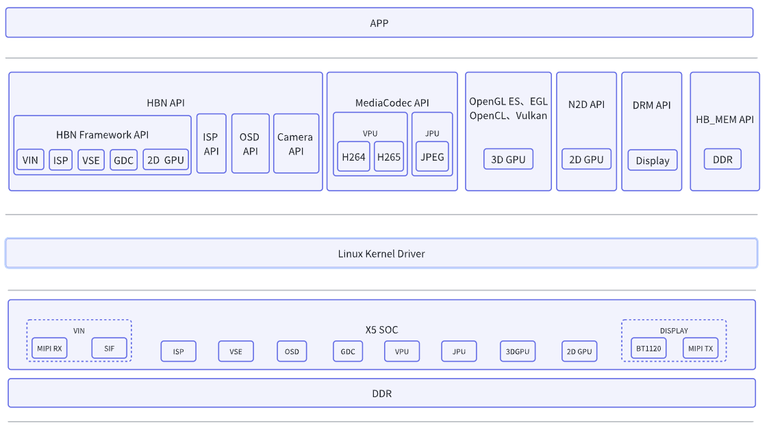
The following describes the function of each API from left to right:
HBN API: IncludesHBN Framework API,ISP API,OSD API,Camera API, covering all modules in the camera capture pipelineHBN Framework API: The core software framework of the multimedia system
Treats each module as a node (vnode), connecting modules to form a pipeline (vflow)
Currently covers VIN, ISP, VSE, GDC, 2DGPU; see HBN Framework Interface Specification for detailsISP API: Used to dynamically configure and retrieve ISP module parameters; see Image Quality ISP for details
Static parameter configuration and data flow of the ISP module are implemented inHBN FrameworkOSD API: Used to create and configure the OSD module. Not covered byHBN Framework API, but can be attached to VSE node channels via interfaces
See Region Processing OSD for detailsCamera API: Used to configure Camera Sensor. Not covered byHBN Framework API, but can be attached to VIN nodes via interfaces
See Video Input Camera for details
MediaCodec API: Controls VPU and JPU modules to achieve H.264, H.265, JPEG encoding/decoding functions; see Video Codec MediaCodec for detailsOpenGL ES, EGL, OpenCL, Vulkan: Interfaces for 3DGPU, standard 3DGPU frameworks; see 3DGPU for detailsN2D API: Interface for 2DGPU; see 2DGPU for details. Some functions are integrated into the HBN framework; use ofN2D APIis recommendedDRM API: Interface for video display module; see Video Output Display for detailsHB_MEM API: Enables management of large physically contiguous memory blocks in user space; see Memory Management Hbmem for detailsEnables video frame data buffering: Memory used by all hardware acceleration units and DMA modules must be physically contiguous
Enables video frame data transfer: Based on dmabuf at the lower level, enables direct transfer of image data between different kernel drivers and between kernel and user space
5.1.4.2. Data Interaction
When processing video frame data, hardware acceleration units require physically contiguous DDR buffers. To meet this requirement, the multimedia system software provides the HB_MEM API with the following characteristics:
User-space memory allocation: Supports allocating large physically contiguous memory blocks in user space, meeting video processing requirements
Dedicated memory region: Allocated memory comes from the
IONregion (a memory area reserved in the device tree, not used by Linux’s standard allocator). See ION System Debug Guide for detailsZero-copy data transfer: Based on the underlying dmabuf framework, enables direct data transfer between different drivers and between kernel and user space, avoiding memory copy operations
Efficient memory management: Uses memory pools (mempool) to avoid frequent memory allocation and release, reducing frequent switching between user and kernel space, thereby improving memory allocation efficiency
Video frame structure support: Provides the structure
hb_mem_graphic_buf_tto describe the content and format information of video frames
Therefore, within the multimedia system software, data exchange between different hardware acceleration units is based on the structure hb_mem_graphic_buf_t. For APIs that do not support hb_mem_graphic_buf_t, conversion can be achieved in various ways, as described below:
The video frame data structure used by
HBN APIandMediaCodec APIishb_mem_graphic_buf_tThe video frame data structure used by
N2D APIisn2d_buffer_t. It can be converted fromhb_mem_graphic_buf_tby extracting the physical address and video parameters. See sample_gpu_2d Usage Guide for detailsDRM APIis also based on dmabuf at the lower level. It can obtain the dmabuf file descriptor fromhb_mem_graphic_buf_tand convert it intodma_buf_map_t. See sample_vot Usage Guide for detailsOpenGL ES, EGL, OpenCL, Vulkan: To be supplemented
When transferring data between different hardware modules, attention must be paid to alignment issues. The input and output resolutions of each module, as well as the alignment requirements for input and output memory, are listed below.
| Module | Input pixels | Output pixels | Input memory stride | Output memory stride |
|---|---|---|---|---|
| SIF | Width and height must be even numbers | Width and height must be even numbers | -(The input is MIPI data, not memory.) | Width: 16-byte alignment |
| ISP | Width and height must be even numbers | Width and height must be even numbers | Width: 16-byte alignment | Width: 16-byte alignment |
| VSE | Width and height must be even numbers | Width: multiple of 16, Height: even number | Width: 16-byte alignment | Width: 16-byte alignment |
| GDC | Width and height must be even numbers | Width and height must be even numbers | Width: 16-byte alignment | Width: 16-byte alignment |
| OSD | Width: multiple of 16, Height: even number | No output | - | - |
| VPU (Encoder) | Width and height must be multiples of 8 | -(The output is raw bitstream, not an image.) | Width: 32-byte alignment | -(The output is raw bitstream, not an image.) |
| VPU (Decoder) | Width and height must be even numbers | Width and height must be even numbers | -(The input is raw bitstream, not an image. ) | Both width and height are required to be 16-byte aligned |
| JPU (Encoder) | Width: multiple of 16, Height: multiple of 8 | -(The output is raw bitstream, not an image.) | Both width and height are required to be 16-byte aligned | -(The output is raw bitstream, not an image.) |
| JPU (Decoder) | Width and height must be even numbers | Width and height must be even numbers | -(The input is raw bitstream, not an image.) | Both width and height are required to be 16-byte aligned |
| 2DGPU | Width: multiple of 64, Height: even number | Width: multiple of 64, Height: even number | Width: 64-byte alignment | Width: 64-byte alignment |
| 3DGPU | No requirements | No requirements | No requirements | No requirements |
| Display(DC8000Nano) | Width and height must be even numbers | -(Will not output to memory) | Width: 32-byte alignment | - (Will not output to memory) |
Note:
2D GPU supports multiple formats. The table above describes the NV12 format (a commonly used format). Different formats have different pixel requirements. For details, see: 2DGPU alignment requirements
For 3D GPU, when calling the function
clCreateBufferwith the flagCL_MEM_USE_HOST_PTR, both the address and size need to be 64-byte aligned.