5.15. ISP - OTP Function
5.15.1. Function Description
Each image sensor and lens has minor optical/color differences. If uniform algorithm parameters are used, the imaging color or brightness may deviate. OTP (One-Time Programmable) refers to a “one-time programmable storage area.” Currently, X5 supports AWB and LSC OTP functions. It writes the white balance calibration data and lens correction data of each camera module at the factory into the sensor EEPROM area, so that the device can automatically read them later and achieve the expected image effect.
5.15.2. Pipeline Introduction
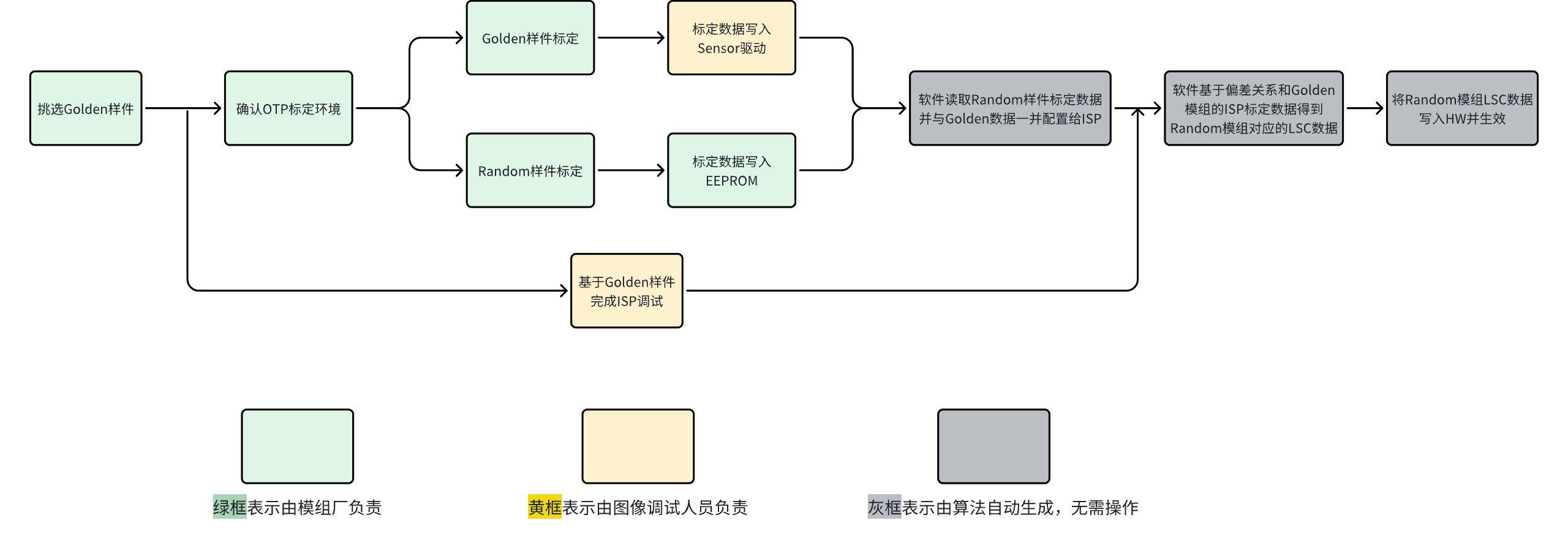
Note: For the current LSC OTP solution, the golden data written in the sensor driver is recommended to cover samples from the same module manufacturer with the same module specifications.
5.15.3. LSC OTP
5.15.3.1. Preparation
Golden Module Selection
Selected by the module manufacturer according to customer requirements.
Golden Module ISP Tuning
Complete the Golden module ISP tuning within the cycle confirmed with the customer, referring to the ISP tuning process guide.
5.15.3.2. Data Calibration
Calibration Environment
The calibration environment for Golden modules and Random modules should be consistent. Refer to the table below for configuration.
| Name | Parameter | Note |
|---|---|---|
| Gain setting | Digital Gain: 1x; Analog Gain: 1x | - |
| Mirror/Flip setting | Mirror OFF; Flip OFF | - |
| WB setting | OFF | - |
| PD setting | OFF | - |
| DPC | OFF | DPC does not need to be set during chart calibration |
| Raw format | Raw10 | - |
| Image size | Any conventional size | Odd sizes are not supported |
| G value requirement | For 10-bit RAW data, the G value is recommended to be around 400-650 after BLC subtraction. | - |
| G value distribution | Center (1/5 width * 1/5 Height) | The region position with G value requirements |
| Module control requirement | After BLC subtraction, center G value / edge G value < 5 | LSC supports up to 16x Gain, but excessive attenuation can cause shading or block artifacts. |
| Recommended color temperature | 5000K | Random and Golden modules need to capture raw data under the same color temperature |
Calibration Process
Place the module within 1cm in front of the light source, adjust the module direction so that the optical axis of the module lens is perpendicular to the light source plane. If using an integrating sphere light source, ensure that the module lens can be completely placed inside the integrating sphere through the window.
Set up the module according to the table requirements in Section 3.1, adjust the light source power so that the G value in the center of the image after BLC subtraction is around 400-650, and capture a RAW image.
Import the captured RAW image into the OTP tool, which will calculate 17x17 and 33x33 LSC_table data. For Random samples, write the generated 17x17 LSC_table into the EEPROM; for Golden samples, write the 33x33 LSC_table into the sensor driver. For data generation examples, see Section 5.
After completing the above steps, ask the image tuning engineer to confirm whether the image performance meets expectations. If it does, proceed with batch programming to complete the OTP calibration.
5.15.3.3. OTP Data Generation Tool
The data generation tool comes in two forms: one provides C code with a static library, requiring parameter modifications in the C code and recompilation. The other parses parameters by reading text files, requiring no recompilation — just modify the parameters in the “otp_data.txt” file.
No Compilation Required
Name the raw image “otp.raw” and modify the parameters in “otp_data.txt”. After completion, run the exe executable file directly.
Parameter Description
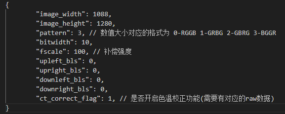
ct_correct_flag: Whether to enable the color temperature correction function. If using this function, place std_lsc_otp_1.raw ~ std_lsc_otp_5.raw and ext_lsc_otp_1.raw ~ ext_lsc_otp_5.raw (10 raw data files total) in the same directory as otp.raw. std_lsc_otp_x.raw: 5 random raw images captured under the same color temperature as the Golden data in the sensor driver. ext_lsc_otp_x.raw: 5 random raw images captured under the actual color temperature on the sensor production line. At this point, the EEPROM of the sensor is programmed with OTP data for the corresponding color temperature. The 5 random raw images for the two production lines need to use 5 identical sensors, and the same sensor numbers must correspond one-to-one.
Calibration of Two Production Line Differences
When the module manufacturer has multiple production lines, if there is a deviation in the color temperature used for calibration between different lines. For example, for A light, one is 3000K and the other is 2800K, which will cause the same module to have slightly different programming values when programming OTP under different light sources, ultimately causing LSC result deviation. You can select 5 random modules to calculate the difference between the two production lines.
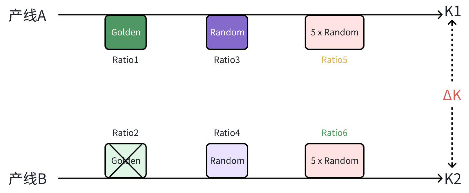
Calibration steps:
Select 5 random modules.
Under the color temperature of production line A (using production line A as the standard), capture 5 raw data images, and name them std_lsc_otp_1.raw ~ std_lsc_otp_5.raw respectively.
Under the color temperature of production line B, capture raw data of the same 5 modules, and name them ext_lsc_otp_1.raw ~ ext_lsc_otp_5.raw respectively.
Afterwards, when using the tool to generate OTP parameters for a Random module on production line B, set ct_correct_flag to 1, and the tool will automatically apply the difference between the two production lines to the OTP parameters.
Example: When using the tool to generate parameters for production line B, suppose the corresponding color temperature for Golden calibration is TL84. You need to capture 5 random modules under TL84 color temperature on both production line A and production line B, name the files accordingly and place them in the same directory as the tool, then set ct_correct_flag to 1.
Note:
If switching to another production line, the same calibration method must be performed again.
The 5 random modules should be as close as possible to the modules being calibrated. When the difference is too large (e.g., excessive optical center position offset), the corrected data will also have a significant deviation from the ideal data.
Compilation Required
The OTP tool currently supports compilation for Windows and Linux platforms. This approach is not recommended.
5.15.3.4. Generated Data Results
The data is saved in a txt file. The first part contains some parameters of the generated data, followed by four 17x17 and four 33x33 data matrices, representing the matrices of 4 channels respectively. The 17x17 data generated for Random modules is written into the EEPROM as OTP data, and the 33x33 data generated for Golden modules is written into the sensor driver.
5.15.3.5. Sensor Driver Example Code
During sensor initialization, call the corresponding interfaces according to the following reference code to set up the OTP function.
#ifdef OTP_EN
        {
                int32_t rett = 0;
                int32_t v,h;
                sensor_otp_t pdata = {0};
                uint16_t r_matrix[17*17] = R_CHN_MATRIX;
                uint16_t gr_matrix[17*17] = GR_CHN_MATRIX;
                uint16_t gb_matrix[17*17] = GB_CHN_MATRIX;
                uint16_t b_matrix[17*17] = B_CHN_MATRIX;
                uint16_t golden_r_matrix[33*33] = R_GOLDEN_MATRIX;
                uint16_t golden_gr_matrix[33*33] = GR_GOLDEN_MATRIX;
                uint16_t golden_gb_matrix[33*33] = GB_GOLDEN_MATRIX;
                uint16_t golden_b_matrix[33*33] = B_GOLDEN_MATRIX;

                pdata.otp_lsc_enable = 1;
                // Currently only supports setting to 1
                pdata.lsc_ct_num = 1;

                for (v = 0; v < SENSOR_OTP_LSC_EEPROM_SIZE; v++) {
                        for (h = 0; h < SENSOR_OTP_LSC_EEPROM_SIZE; h++) {
                                pdata.lsc_data[0].r[v][h] = r_matrix[v * SENSOR_OTP_LSC_EEPROM_SIZE + h];
                                pdata.lsc_data[0].gr[v][h] = gr_matrix[v * SENSOR_OTP_LSC_EEPROM_SIZE + h];
                                pdata.lsc_data[0].gb[v][h] = gb_matrix[v * SENSOR_OTP_LSC_EEPROM_SIZE + h];
                                pdata.lsc_data[0].b[v][h] = b_matrix[v * SENSOR_OTP_LSC_EEPROM_SIZE + h];
                        }
                }

                for (v = 0; v < SENSOR_OTP_LSC_H_GRID_NUM; v++) {
                        for (h = 0; h < SENSOR_OTP_LSC_H_GRID_NUM; h++) {
                                pdata.lsc_data[0].golden_r[v][h] = golden_r_matrix[v * 33 + h];
                                pdata.lsc_data[0].golden_gr[v][h] = golden_gr_matrix[v * 33 + h];
                                pdata.lsc_data[0].golden_gb[v][h] = golden_gb_matrix[v * 33 + h];
                                pdata.lsc_data[0].golden_b[v][h] = golden_b_matrix[v * 33 + h];
                        }
                }

                rett = ioctl(sensor_info->sen_devfd, SENSOR_OTP_PARAM, &pdata);
                if (rett < 0) {
                        vin_err("ioctl SENSOR_OTP_PARAM fail\n");
                }
                printf("sc202cs otp3-D65 enable\n");
        }
#endif
5.15.4. AWB OTP
5.15.4.1. Preparation
Golden Module Selection
Selected by the module manufacturer according to customer requirements.
Golden Module ISP Tuning
Complete the Golden module ISP tuning within the cycle confirmed with the customer, referring to the ISP tuning process guide.
5.15.4.2. Data Calibration
Calibration Environment
The calibration environment for Golden modules and Random modules should be consistent. Refer to the table below for configuration.
| Name | Parameter | Note |
|---|---|---|
| Gain setting | Digital Gain: 1x; Analog Gain: 1x | - |
| Mirror/Flip setting | Mirror OFF; Flip OFF | - |
| WB setting | OFF | - |
| PD setting | OFF | - |
| DPC | OFF | DPC does not need to be set during chart calibration |
| Raw format | Raw10 | - |
| Image size | Any conventional size | Odd sizes are not supported |
| G value requirement | For 10-bit RAW data, the G value is recommended to be around 400-650 after BLC subtraction. | - |
| G value distribution | Center (1/5 width * 1/5 Height) | The region position with G value requirements |
| Module control requirement | After BLC subtraction, center G value / edge G value < 5 | LSC supports up to 16x Gain, but excessive attenuation can cause shading or block artifacts. |
| Recommended color temperature | 3100K, 4000K, 5800K | Random and Golden modules need to capture raw data under the same color temperature |
Calibration Process
It is recommended to use a gray card for calibration. If using an integrating sphere light source, ensure that the module lens can be completely placed inside the integrating sphere through the window.
Set up the module according to the calibration environment table in Section 3.1, adjust the light source power so that the G value in the center of the image after BLC subtraction is around 400-650, and capture a RAW image.
Import the captured RAW image into the OTP tool, which will calculate R/GR/GB/B/rgRatio/bgRatio data (the data range depends on the raw data format; 16-bit programming is recommended). For Random samples, write the generated data into the sensor EEPROM; for Golden samples, write the data into the sensor driver. For data generation examples, see Section 5. Data Generation.
After completing the above steps, ask the image tuning engineer to confirm whether the image performance meets expectations. If it does, proceed with batch programming to complete the OTP calibration.
5.15.4.3. OTP Data Generation Tool
The AWB OTP tool is an exe executable file (awb_otp.exe). The raw image configuration parameters and awb ratio parameters required for calculation are read in through a txt file (otp_data.txt), and the OTP data calculation results are recorded in a txt file (otp_result.txt).
Usage
Name the raw image to be calculated as “otp.raw”,
Configure the relevant parameters in “otp_data.txt”,
Run the exe executable file to get the calculation results, which are saved in the “otp_result.txt” file.
Parameter Description
image_width: Image width image_height: Image height pattern: Image Bayer pattern, the corresponding formats for the numeric values are 0-RGGB, 1-GRBG, 2-GBRG, 3-BGGR bls_r/bls_gr/bls_gb/bls_b: BLS values for r/gr/gb/b channels respectively. During image statistics, this value will be directly subtracted. awb_ratio: Use the central area of the raw data with a size of 1/awb_ratio of the raw image width and height for statistics. Other areas will not be included in the statistics. std_rg_ratio_x: Used for calibrating two production line differences. std corresponds to the standard production line. This parameter is the rg_ratio in the color temperature calibration result (otp_result.txt) of module x on this production line. std_bg_ratio_x: Used for calibrating two production line differences. std corresponds to the standard production line. This parameter is the bg_ratio in the color temperature calibration result (otp_result.txt) of module x on this production line. ext_rg_ratio_x: Used for calibrating two production line differences. ext corresponds to the other production line. This parameter is the rg_ratio in the color temperature calibration result (otp_result.txt) of module x on this production line. ext_bg_ratio_x: Used for calibrating two production line differences. ext corresponds to the other production line. This parameter is the bg_ratio in the color temperature calibration result (otp_result.txt) of module x on this production line.
Calibration of Two Production Line Differences
When the module manufacturer has multiple production lines, if there is a deviation in the color temperature used for calibration between different lines. For example, for A light, one is 3000K and the other is 2800K, which will cause the same module to have slightly different programming values when programming OTP under different light sources, ultimately causing AWB result deviation. You can select 5 random modules to calculate the difference between the two production lines.
Calibration steps:
Select 5 random modules.
Under the high, medium, and low color temperatures of production line A, capture raw data, set the 20 parameters such as std_rg_ratio_x to 1, and use the tool to generate rg_ratio and bg_ratio for the 5 modules at three color temperatures.
Under the high, medium, and low color temperatures of production line B, capture raw data of the same 5 modules, set the 20 parameters such as std_rg_ratio_x to 1, and use the tool to generate rg_ratio and bg_ratio for the 5 modules at three color temperatures.
Afterwards, when using the tool to generate OTP parameters for a Random module on production line B, configure the 20 parameters such as std_rg_ratio_x with the corresponding color temperature results, and the tool will automatically apply the difference between the two production lines to the OTP parameters.
Example: When using the tool to generate parameters for production line B, suppose the corresponding color temperature is TL84. You need to configure std_rg_ratio_1 and std_bg_ratio_1 to the rg_ratio and bg_ratio generated by the first random module under TL84 color temperature on production line A, and std_rg_ratio_2, std_bg_ratio_2, etc. accordingly. You need to configure ext_rg_ratio_1 and ext_bg_ratio_1 to the rg_ratio and bg_ratio generated by the first random module under TL84 color temperature on production line B, and ext_rg_ratio_2, ext_bg_ratio_2, etc. accordingly.
Note: If switching to another production line, the same calibration method must be performed again. If this function is not used, all 20 parameters such as std_rg_ratio_x must be configured to 1.
5.15.4.4. Generated Data Results
The data is stored in the otp_result.txt file. The first part covers the raw image configuration data and other parameters used for calculation. The generated channel statistics and ratio data are recorded under the “AWB OTP calculation result” field, which represents the AWB OTP related data at the corresponding color temperature. The data generated for Random modules is written into the EEPROM, while the data generated for Golden modules is recorded in the sensor driver.
5.15.4.5. Sensor Driver Example Code
During sensor initialization, call the corresponding interfaces according to the following reference code to set up the OTP function.
{
        sensor_otp_t pdata = {0};
        pdata.otp_awb_enable = 1;
        pdata.awb_ct_num = 3;
        pdata.awb_golden_ct_num = 3;

        pdata.awb_data[0].color_temperature = COLOR_TEMPERATURE_3100K;
        pdata.awb_data[0].r = 36;
        pdata.awb_data[0].gr = 76;
        pdata.awb_data[0].gb = 76;
        pdata.awb_data[0].b = 49;
        pdata.awb_data[0].rg_ratio = 10;
        pdata.awb_data[0].bg_ratio = 10;

        pdata.awb_golden_data[0].color_temperature = COLOR_TEMPERATURE_3100K;
        pdata.awb_golden_data[0].r = 79;
        pdata.awb_golden_data[0].gr = 159;
        pdata.awb_golden_data[0].gb = 161;
        pdata.awb_golden_data[0].b = 105;
        pdata.awb_golden_data[0].rg_ratio = 2;
        pdata.awb_golden_data[0].bg_ratio = 2;

        pdata.awb_data[1].color_temperature = COLOR_TEMPERATURE_4000K;
        pdata.awb_data[1].r = 36;
        pdata.awb_data[1].gr = 76;
        pdata.awb_data[1].gb = 76;
        pdata.awb_data[1].b = 49;
        pdata.awb_data[1].rg_ratio = 10;
        pdata.awb_data[1].bg_ratio = 10;

        pdata.awb_golden_data[1].color_temperature = COLOR_TEMPERATURE_4000K;
        pdata.awb_golden_data[1].r = 79;
        pdata.awb_golden_data[1].gr = 159;
        pdata.awb_golden_data[1].gb = 161;
        pdata.awb_golden_data[1].b = 104;
        pdata.awb_golden_data[1].rg_ratio = 2;
        pdata.awb_golden_data[1].bg_ratio = 2;

        pdata.awb_data[2].color_temperature = COLOR_TEMPERATURE_5800K;
        pdata.awb_data[2].r = 35;
        pdata.awb_data[2].gr = 76;
        pdata.awb_data[2].gb = 76;
        pdata.awb_data[2].b = 49;
        pdata.awb_data[2].rg_ratio = 25;
        pdata.awb_data[2].bg_ratio = 25;

        pdata.awb_golden_data[2].color_temperature = COLOR_TEMPERATURE_5800K;
        pdata.awb_golden_data[2].r = 79;
        pdata.awb_golden_data[2].gr = 159;
        pdata.awb_golden_data[2].gb = 161;
        pdata.awb_golden_data[2].b = 105;
        pdata.awb_golden_data[2].rg_ratio = 23;
        pdata.awb_golden_data[2].bg_ratio = 23;
        printf("awb otp enable\n");
        hbn_camera_enable_otp(cam_fd, &pdata);  //cam_fd is created by hbn_camera_create
}