5.11. Video Output - Display
5.11.1. Module Description
The Display subsystem is the video display engine in the X5 project, primarily responsible for providing video output at various resolutions.
5.11.1.1. Hardware Block Diagram
The Display subsystem consists of the following modules:
MIPI DSI Controller: Implements high-speed data transmission between the SoC and display devices, compliant with the MIPI protocol.MIPI CSI TX Controller: Implements the device-side CSI-2 protocol. The CSI-2 link protocol specification is part of the communication standard defined by the MIPI Alliance, suitable for chip-to-chip communication in mobile systems.MIPI D-PHY: The physical layer for both MIPI CSI TX and MIPI DSI.BT1120: Complies with the ITU-R BT.1120 standard, capable of driving external HDMI devices to achieve 4K display.DC8000Nano: A high-performance, low-power display processor.
The relationship between these modules is shown in the diagram below:
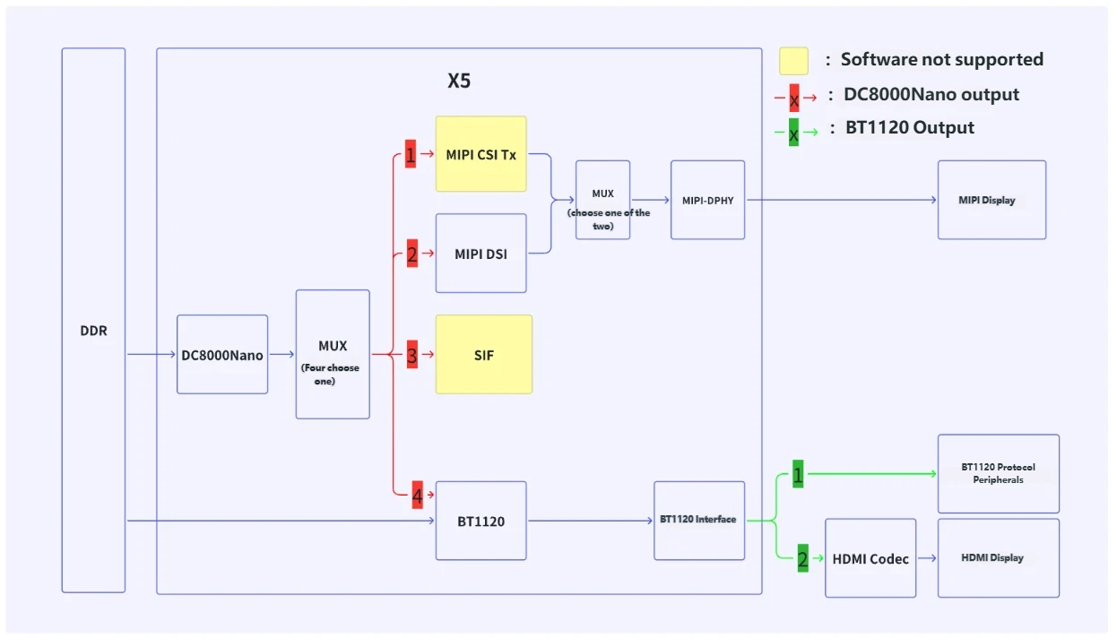
In the above diagram, images from DDR can be output to external displays via three paths:
Path 1: Data from DDR passes through DC8000Nano, MIPI DSI, and MIPI-DPHY to the MIPI display.
Path 2: Data from DDR passes through DC8000Nano and BT1120 to the external display.
Path 3: Data from DDR is directly output via BT1120 to the external display.
Note:
DC8000Nano supports four output paths, but the yellow portion is currently not supported by software.
BT1120 output can connect to BT1120 protocol devices or be converted via a bridge chip to other protocols such as HDMI.
5.11.1.2. Specifications
DC8000Nano
Supports 4 hardware layers: Video/Graphic layer, Overlay layer0, Overlay layer1, Cursor layer.
Video/Graphic layer supports: AR12 AR15 RG16 RG24 AR24 RA12 RA15 RA24 AB12 AB15 BG16 BG24 AB24 BA12 BA15 BA24 YUYV YVYU NV12 NV21 XR24 XB24
Overlay layer0 supports: AR12 AR15 RG16 AR24 RA12 RA15 RA24 AB12 AB15 BG16 AB24 BA12 BA15 BA24 YUYV NV12 NV21
Overlay layer1 supports: AR12 AR15 RG16 RG24 AR24 RA12 RA15 RA24 AB12 AB15 BG16 BG24 AB24 BA12 BA15 BA24 YUYV YVYU XR24 XB24
Cursor layer supports: AR24
When input format is NV12, maximum resolution supported is 3840x2160@30FPS; for other formats, up to 2560x1440@60FPS.
Supports image data output via BT1120/DSI/CSI-TX.
Supports color remapping, Alpha blending, layer order definition, Gamma correction, dithering, and chroma keying.
Integrated 2D GPU extension enables: layer rotation, layer mirroring, and scaling from 1/8x to 8x.
BT1120
Maximum output resolution up to 3840x2160@30FPS.
Input and output support 8-bit YUV422 and 8-bit YUV420.
Storage modes:
Semi-planar mode: used to store YUV422 and YUV420 data in separate Y and UV memory buffers.
Supports packed YUV422 mode stored in memory.
Operation modes:
Offline Mode: reads pixel data from DDR.
Online Mode: receives data from display IPs (e.g., DC8000Nano).
Supports two scan modes: Progressive Mode and Interleaved Mode.
Output characteristics:
Output pixel data width is 16 bits.
Supports DDR (Double Data Rate) or SDR (Single Data Rate) for pixel clock output.
MIPI DSI
Supports up to 4 Lanes output.
Transmission capability:
Each lane supports up to 2.5 Gbps data rate.
Supports up to four data lanes.
Operation modes: supports Non-continuous mode and Continuous mode.
MIPI DSI TX
Supports up to 2.5 Gbps per lane.
Supports up to 4 Lanes output.
5.11.1.3. Software Description
The X5 display subsystem software integrates with the DRM framework, which consists of user-space libdrm and kernel-space DRM drivers.
Overview of the DRM Framework
Within the DRM framework, the display subsystem is divided into several components: CRTC, Encoder, Planes, Connector, Framebuffer, Bridge, Panel.
| DRM Concept | Meaning | Hardware Module Name |
|---|---|---|
| CRTC | Abstraction of the display controller, responsible for managing core resources of the display device and defining output characteristics of the displayed content | DC8000Nano and BT1120 |
| Encoder | Intermediate component between CRTC and Connector, responsible for handling data format and signal transmission | DSI Encoder: responsible for converting data into MIPI DSI signals |
| Planes | Fundamental unit of display data, used for multi-layer image composition (Overlay) | 4 hardware layers of DC8000Nano |
| Connector | Physical interface abstraction of the display device | HDMI interface, DSI interface |
| Bridge | Module used to extend Encoder functionality, supporting complex display signal processing | Conversion chip that converts BT1120 to HDMI protocol |
| Panel | Abstraction of the actual display panel, defining attributes and behaviors of the display device | Display panel (physical panel) |
Mapping Between DRM Debug Information and Hardware
During DRM usage, the main components of interest are Planes, CRTC, and Connector. After system boot, the modetest command can be used to view these resources.
Running modetest
Note:
The output of
modetestmay vary across different versions.Before running the
modetestcommand, ensure the following commands have been executed:
modprobe panel-jc-050hd134
modprobe galcore
modprobe vio_n2d
modprobe lontium_lt8618
modprobe vs-x5-syscon-bridge
modprobe vs_drm
root@buildroot:/userdata/bin# modetest -M vs-drm -a
Encoders:
id      crtc    type    possible crtcs  possible clones
57      0       Virtual 0x00000001      0x00000001
69      0       Virtual 0x00000003      0x00000002
72      0       DSI     0x00000001      0x00000004
74      0       TMDS    0x00000003      0x00000008

Connectors:
id      encoder status          name            size (mm)       modes   encoders
73      0       connected       DSI-1           62x110          1       72
  modes:
        index name refresh (Hz) hdisp hss hse htot vdisp vss vse vtot
  #0 720x1280 61.99 720 752 772 792 1280 1300 1304 1324 65000 flags: nhsync, nvsync; type: preferred, driver
  props:
   	[...]
75      0       connected       HDMI-A-1        600x340         40      74
  modes:
        index name refresh (Hz) hdisp hss hse htot vdisp vss vse vtot
  #0 1920x1080 60.00 1920 2008 2052 2200 1080 1084 1089 1125 148500 flags: phsync, pvsync; type: preferred, driver
  #1 1920x1080 60.00 1920 2008 2052 2200 1080 1084 1089 1125 148500 flags: phsync, pvsync; type: driver
 	[...]
  props:
	[...]

CRTCs:
id      fb      pos     size
31      0       (0,0)   (0x0)
  #0  nan 0 0 0 0 0 0 0 0 0 flags: ; type:
  props:
	[...]
63      0       (0,0)   (0x0)
  #0  nan 0 0 0 0 0 0 0 0 0 flags: ; type:
  props:
	[...]

Planes:
id      crtc    fb      CRTC x,y        x,y     gamma size      possible crtcs
33      0       0       0,0             0,0     0               0x00000001
  formats: AR12 AR15 RG16 AR24 RA12 RA15 RA24 AB12 AB15 BG16 AB24 BA12 BA15 BA24 YUYV NV12 NV21 XR24 XB24
  props:
	[...]
41      0       0       0,0             0,0     0               0x00000001
  formats: AR12 AR15 RG16 RG24 AR24 RA12 RA15 RA24 AB12 AB15 BG16 BG24 AB24 BA12 BA15 BA24 YUYV YVYU NV12 NV21 XR24 XB24
  props:
	[...]
48      0       0       0,0             0,0     0               0x00000001
  formats: AR12 AR15 RG16 RG24 AR24 RA12 RA15 RA24 AB12 AB15 BG16 BG24 AB24 BA12 BA15 BA24 YUYV YVYU NV12 NV21 XR24 XB24
  props:
	[...]
53      0       0       0,0             0,0     0               0x00000001
  formats: AR24
  props:
	[...]
64      0       0       0,0             0,0     0               0x00000002
  formats: NV16 NV61 NV12 NV21 YUYV YVYU UYVY VYUY
  props:
        8 type:
                flags: immutable enum
                enums: Overlay=0 Primary=1 Cursor=2
                value: 1
	[...]

Frame buffers:
id      size    pitch
Analysis of modetest Output
The mapping between DRM debug information and hardware is described as follows:
CRTC:
31 → DC8000Nano
63 → BT1120
Connectors:
73 → MIPI-DSI
75 → HDMI (On the EVB, a BT1120-to-HDMI converter chip, model LT8618SXB, is connected)
Planes:
33 → Primary Plane (implemented via integrated 2D GPU for rotation and scaling)
41 → Overlay0
48 → Overlay1
53 → Cursor
64 → BT1120 Primary Plane
Note:
The layer with ID 64 can only be used when the CRTC is 63 (BT1120).
Quick DRM Experience
Based on the information obtained from modetest, we can execute the following command to test HDMI functionality. Before execution, ensure a display supporting 1080P@60Hz mode is connected:
modetest -M vs-drm -a -s 75@31:1920x1080 -P 33@31:1920x1080@NV12
After the command completes, the SMPTE test color bars ECR-1-1978 should appear on the display:

5.11.2. Reference Examples
Example code for the Display section can be found in the sample_vot section.