3.17. Sunrise camera Development Guide
3.17.1. Sunrise camera System Design
3.17.1.1. System Block Diagram
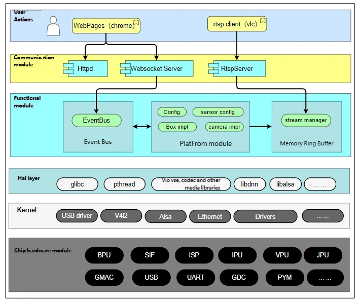
Sunrise camera implements various application solutions such as intelligent cameras and intelligent analysis boxes.
The Sunrise camera source code includes the WebPages layer for user interaction, the communication module layer, and the functional module layer; this document mainly introduces the design of these three modules.
The Hal layer modules include interface libraries for multimedia-related modules, BPU inference libraries, etc.
The Kernel version includes standard driver libraries and system BSP.
The software architecture is shown below:
3.17.1.2. Microkernel Design
The microkernel architecture, also known as “plugin architecture,” refers to software with a relatively small kernel where main functions and business logic are implemented through plugins.
The kernel typically contains only the minimal functions required for system operation. Plugins are independent of each other, and communication between plugins should be minimized to avoid interdependencies.
3.17.1.3. Advantages and Disadvantages of the Architecture
Advantages
Good functional extensibility: new features can be added by developing plugins.
Functional isolation: plugins can be independently loaded and unloaded, making deployment easier.
High customizability, adaptable to different development needs.
Supports incremental development, allowing features to be added gradually.
Disadvantages
Poor scalability: the kernel is usually a single unit and difficult to distribute.
Higher development difficulty due to the need for communication between plugins and the kernel, as well as plugin registration.
3.17.2. Sunrise camera Architecture View
3.17.2.1. Module Division
| Module | Directory | Description |
|---|---|---|
| Event Bus Module | communicate | Implements event registration, reception, and distribution |
| Common Library Module | common | Common operation functions: log/lock, circular memory buffer, thread operations, queue operations, etc. |
| Camera Module | Platform | Chip platform-related code, encapsulating hardware differences |
| External Interaction Module | Transport | Device external interaction components: rtspserver, websocket, etc. |
| Main Program Entry | Main | Main function entry |
Top-level Code Structure
.
├── build.sh			# When this source code is placed under BPS's PlatformSDK/unittest directory, this build script can be used after entering the lunch compilation environment
├── common				# Common library module code
├── communicate			# Event bus module
├── config				# Compilation configuration directory
├── docs				# User and development documentation
├── main				# Main entry program
├── Makefile			# Build script
├── makefile.param		# Compilation configuration
├── Platform			# Camera module, platform, application scenario code; chip IP-related code is implemented in this directory
├── start_app.sh	    # Startup script on device, can be configured for auto-start on power-up
├── Transport			# Implementation code for rtspserver and websocket modules
└── WebServer			# lighttpd program, configuration, and web pages
Compilation
Check whether the corresponding cross-compilation toolchain has been installed, generally located in the toolchain directory of the BSP package; refer to the BSP development manual for detailed configuration.
After installing the cross-compilation toolchain, run
maketo compile from any directory. Asunrise_cameradirectory will be generated in the current source directory. Package thesunrise_cameradirectory, theWebServerdirectory, and thestart_app.shfile, then download them to the device for execution.
3.17.2.2. Event Bus Module (communicate)
Overview
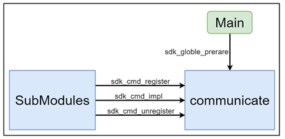
The event bus module is the smallest operational unit; it calls different module registration interface functions based on compilation options and handles the reception and distribution of commands (CMDs) across modules.
During inter-module interactions, if a received CMD has been registered and enabled, it is forwarded to the responsible sub-module for processing. After processing, the result is returned to the requesting module.
If a received CMD is not registered or disabled during inter-module interaction, the CMD call fails.
Function Description
Static plug-in and plug-out control of modules
Command (CMD) forwarding between modules
Example:
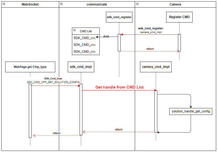
In the camera submodule, the command SDK_CMD_CAMERA_GET_CHIP_TYPE is defined. After registering this CMD using the camera_cmd_register function, when the websocket submodule receives a web page request to get the chip type, the websocket module can invoke the interface in the camera submodule via the following code.
The entire process is illustrated below:
Module Code Structure
.
├── include
│   ├── sdk_common_cmd.h			# Defines all sub-module CMDs in the system
│   ├── sdk_common_struct.h		# Defines data structures used by each CMD
│   └── sdk_communicate.h			# Defines interfaces of this module
├── Makefile
└── src
    └── sdk_communicate.c			# Interface implementation code
Interface Description
sdk_globle_prerare
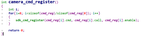
Each submodule’s xxx_cmd_register() function is centralized into this function. During startup, the main program calls this interface to register and enable all necessary CMDs of submodules into the subsystem.
Each submodule must implement xxx_cmd_register(), which registers the submodule’s CMDs. This is the fundamental prerequisite for the system to operate normally.
Example:
sdk_cmd_register
CMD registration interface.
sdk_cmd_unregister
CMD unregistration interface.
sdk_cmd_impl
Submodules use this interface to call interfaces implemented by other submodules.
3.17.2.3. Common Library Module (common)
Overview
A common utility library that includes, but is not limited to, logging, locking, thread encapsulation, circular buffer operations, cJSON, base64, etc.
This module primarily encapsulates common classes and functions used in programming to avoid duplicate implementations in multiple locations.
Updates to this module affect all modules and should be handled with caution.
Function Description
None
Module Code Structure
.
├── Makefile					# Build script
├── makefile.param
└── utils
    ├── include				    # Header files
    │   ├── aes256.h
    │   ├── base64.h
    │   ├── cJSON_Direct.h
    │   ├── cJSON.h
    │   ├── cmap.h
    │   ├── common_utils.h
    │   ├── cqueue.h
    │   ├── gen_rand.h
    │   ├── lock_utils.h
    │   ├── mqueue.h
    │   ├── mthread.h
    │   ├── nalu_utils.h
    │   ├── sha256.h
    │   ├── stream_define.h
    │   ├── stream_manager.h
    │   └── utils_log.h
    ├── Makefile
    └── src                      # Implementation source code
        ├── aes256.c
        ├── base64.c
        ├── cJSON.c
        ├── cJSON_Direct.c
        ├── cmap.c
        ├── common_utils.c
        ├── cqueue.c
        ├── gen_rand.c
        ├── lock_utils.c
        ├── mqueue.c
        ├── mthread.c
        ├── nalu_utils.c
        ├── sha256.c
        ├── stream_manager.c
        └── utils_log.c
3.17.2.4. Platform Module
Overview
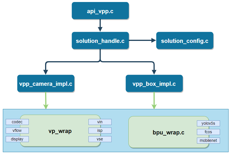
The module mainly includes video encoding, ISP control, image control, OSD watermarking, snapshot capture, video output, algorithm computation, etc.
The internal structure of this module is as follows:
api_vpp serves as the entry point of this module, defining the supported CMD command set;
solution_handle handles application configuration read/write and scene interface assignment;
vpp_camera_impl, vpp_box_impl implement application scenario functions;
vp_wrap encapsulates interfaces of the multimedia module;
bpu_wrap module encapsulates algorithm inference interfaces and post-processing methods.
Function Description
To add a new application scenario implementation, simply implement the interfaces defined in the vpp_ops_t structure.
typedef struct vpp_ops {
	int (*init_param)(void); // Initialize configuration parameters for modules such as VIN, VSE, VENC, BPU
	int (*init)(void); // SDK initialization, initialize according to configuration
	int (*uninit)(void); // De-initialization
	int (*start)(void); // Start various media-related modules
	int (*stop)(void); // Stop
	// All CMDs supported by this module are implemented through the following two interfaces
	int (*param_set)(SOLUTION_PARAM_E type, char* val, unsigned int length);
	int (*param_get)(SOLUTION_PARAM_E type, char* val, unsigned int* length);
} vpp_ops_t;
The flow to start an application solution (using vpp_camera as an example) is as follows:
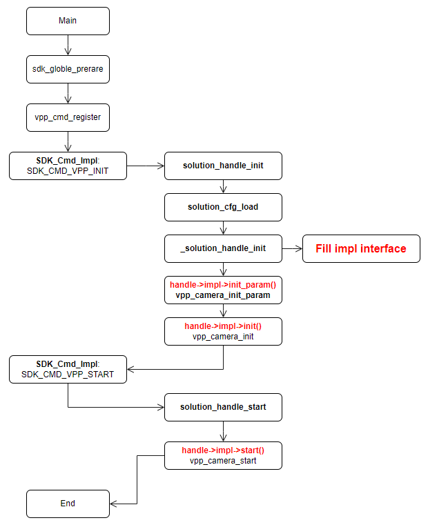
Initialization and startup procedures for other submodules can follow this flowchart.
Module Code Structure
Code path: Platform/x5
.
├── api                                   # CMD registration
├── bpu_wrap                              # Encapsulation of BPU algorithm interface usage
├── main                                  # Actual functional interface implementation for CMD registration
├── Makefile                              # Build script
├── makefile.param                        # Compilation configuration
├── model_zoom                            # Algorithm model repository
├── test_data                             # Stores test video streams and program configuration files
├── tools                                 # live555MediaServer RTSP streaming test program; place video files in this directory and run the program to automatically establish a streaming service
├── vpp_impl                              # Implementation of application scenario functions
├── vp_sensors -> ../../../vp_sensors/    # Camera Sensor configuration code; shared with other sample modules
└── vp_wrap                               # Encapsulation of multimedia interfaces
3.17.2.5. External Interaction Module (Transport)
Overview
Specific submodules that interact with terminals or platforms following transmission protocols; includes network-based modules such as rtspserver and websocket.
This interaction module involves the most inter-module communication and must strictly adhere to design conventions. All data requests to other modules must be processed through defined module CMDs.
Media Server Module
This module is an encapsulation implementation of MediaServer. It encapsulates MediaServer into several simple interfaces such as init, create, push_data, destroy and unint. Currently only RTSP protocol is supported.
For the startup and use of this module, please refer to the process introduction in the Main Program Entry chapter.
Websocket Server Module
This module handles interactive operations with the web interface. After performing actions on the web interface, the websocket server receives corresponding commands and parameters of a certain kind, which are processed in the handle_user_msg function in handle_user_massage.c. To add new interaction commands, extend this function.
Currently supported interaction commands: scene switching, scene parameter get/set, chip type retrieval, H.264 bitrate setting, system time synchronization, websocket stream pull/start/stop, etc.
3.17.2.6. Main Program Entry (main)
Overview
Main program entry point for module startup.
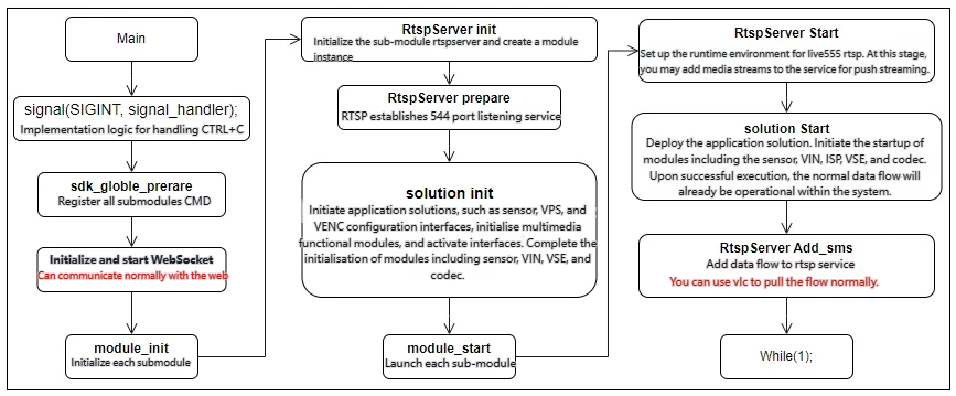
The current basic submodule startup order is as follows. Note that the startup sequence must respect dependencies among submodules.
Execution Flow
3.17.2.7. WebServer
Overview
This module provides a lighttpd-based web httpd service, allowing users to directly preview video and configure application scenarios via a browser.
Function Description
Provides lighttpd compilation instructions, dependencies, pre-compiled executable programs for development boards, and a pre-configured configuration file. Web pages, CSS, and JS files are stored under the lighttpd/webpages directory.
Module Code Structure
.
├── fcgi					# FCGI module library
│   ├── include
│   ├── lib
│   └── version.txt
├── sc_lighttpd				# lighttpd
│   ├── cache
│   ├── cgi-bin
│   ├── config				# Directly usable configuration files
│   ├── lib
│   ├── log
│   ├── sbin
│   ├── server.pem
│   ├── share
│   ├── socktes
│   ├── upload
│   ├── vhosts
│   └── webpages			# Web pages, CSS, JS files
├── pcre					# lighttpd dependency
│   ├── include
│   ├── lib
│   └── version.txt
├── README.txt
└── start_lighttpd.sh		# Script to start WebServer independently
3.17.3. Using BPU for Algorithm Inference
3.17.3.1. Overview
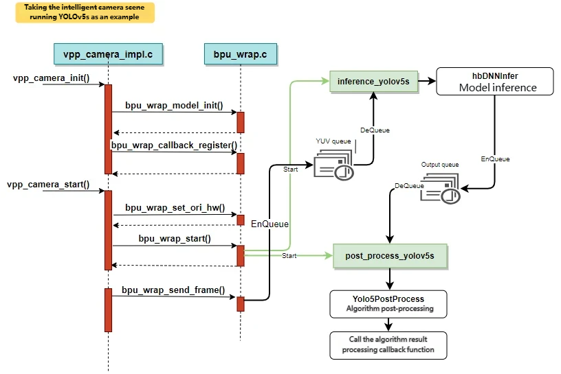
This module performs algorithm model loading, data pre-processing, inference, post-processing, and returns results in JSON format.
The module runtime sequence is as follows:
3.17.3.2. Adding a New Model Procedure
Currently, sunrise_camera supports only a limited number of algorithm models. In practical applications, it’s inevitable to test other models. This section describes the basic steps to add a new algorithm model.
| Item | Source File | Description |
|---|---|---|
| Prepare Algorithm Model | Place in Platform/x5/model_zoom directory (.bin, .hbm) | Add fixed-point algorithm models that can run on the development board |
| Add Model Configuration | bpu_wrap.c | In bpu_models, add the new model name, specify the model file, and define inference and post-processing function interfaces |
| Inference Thread Handler | bpu_wrap.c | In the handler, prepare output tensors, call hbDNNInfer for inference, then place results into the output queue. Example: inference_yolov5s |
| Post-processing Thread Function | bpu_wrap.c | Retrieve algorithm results from the output queue, call post-processing methods to generate JSON-formatted result strings. If a callback is set, invoke it. Example: post_process_yolov5s |
| Post-processing Code | yolov5_post_process.cpp | Each algorithm model requires a corresponding post-processing method. For example, classification models map returned IDs to class names; detection models map bounding boxes to original image coordinates. |
| Add Rendering Handling on Web Page | index.js | Optional |
Prepare Algorithm Model
Two types of algorithm models are supported on the development board, with file extensions .bin and .hbm:
bin model: Model obtained through algorithm toolchain conversion (PTQ), suffixed with
.binhbm model: Algorithm model directly trained via a fixed-point training framework (QAT)
Refer to the Quantization Toolchain Development Guide for detailed algorithm model development instructions.
Add Initialization Process
Define a new algorithm model in the bpu_models array in bpu_wrap.c, adding the model name, specifying the model file, and linking inference and post-processing function interfaces:
bpu_model_descriptor bpu_models[] = {
	{
		.model_name = "yolov5s",                                   // Algorithm name, displayed to users on the web client for selection
		.model_path = "../model_zoom/yolov5s_672x672_nv12.bin",    // Algorithm model file
		.inference_func = inference_yolov5s,                       // Inference function
		.post_proc_func = post_process_yolov5s                     // Post-processing function; if simple, can be merged into the inference function
	},
	... (omitted) ...
};
When the algorithm task starts, the corresponding inference and post-processing threads are launched based on model_name.
Inference Thread Handler
In the inference thread, prepare the output tensor; retrieve YUV data from the YUV queue, call HB_BPU_runModel to perform inference and obtain results; then push the results into the output queue for post-processing.
static void *inference_yolov5s(void *ptr)
{
	// Prepare model output node tensors; 5 sets of output buffers rotate; simple handling, assuming post-processing is faster than inference
	hbDNNTensor output_tensors[5][3];
	int32_t cur_ouput_buf_idx = 0;
	for (i = 0; i < 5; i++) {
		ret = prepare_output_tensor(output_tensors[i], dnn_handle);
		if (ret) {
			SC_LOGE("prepare model output tensor failed");
			return NULL;
		}
	}

	while (privThread->eState == E_THREAD_RUNNING) {
		// Retrieve image data for algorithm computation, typically in NV12 YUV format
		if (mQueueDequeueTimed(&bpu_handle->m_input_queue, 100, (void**)&input_tensor) != E_QUEUE_OK)
			continue;

        // Model inference
		hbDNNInferCtrlParam infer_ctrl_param;
		HB_DNN_INITIALIZE_INFER_CTRL_PARAM(&infer_ctrl_param);
		ret = hbDNNInfer(&task_handle,
				&output,
				&input_tensor->m_dnn_tensor,
				dnn_handle,
				&infer_ctrl_param);

		// Enqueue post-processing data
		Yolo5PostProcessInfo_t *post_info;
		post_info = (Yolo5PostProcessInfo_t *)malloc(sizeof(Yolo5PostProcessInfo_t));
		… …
		mQueueEnqueue(&bpu_handle->m_output_queue, post_info);
		cur_ouput_buf_idx++;
		cur_ouput_buf_idx %= 5;
}
}
Post-processing Thread Function
In the post-processing thread, retrieve algorithm results from the output queue; call the post-processing function; invoke the algorithm task callback to handle results (currently callbacks send results directly to the web for rendering).
static void *post_process_yolov5s(void *ptr)
{
	tsThread *privThread = (tsThread*)ptr;
	Yolov5PostProcessInfo_t *post_info;

	mThreadSetName(privThread, __func__);

	bpu_handle_t *bpu_handle = (bpu_handle_t *)privThread->pvThreadData;
	while (privThread->eState == E_THREAD_RUNNING) {
		// Retrieve data from post-processing data queue
		if (mQueueDequeueTimed(&bpu_handle->m_output_queue, 100, (void**)&post_info) != E_QUEUE_OK)
			continue;

		char *results = Yolov5PostProcess(post_info); // Perform post-processing, e.g., obtain bounding boxes, filter low-confidence results, scale box dimensions to display video size

		if (results) {
			if (NULL != bpu_handle->callback) {
				// Algorithm result callback; currently sends results via websocket to browser
				bpu_handle->callback(results, bpu_handle->m_userdata);
			} else {
				SC_LOGI("%s", results);
			}
			free(results);
		}
		if (post_info) {
			free(post_info);
			post_info = NULL;
		}
	}
	mThreadFinish(privThread);
	return NULL;
}
Post-processing Code
It is recommended to add a post-processing method for each algorithm model:
yolov5: yolo5_post_process.cpp
mobilenet_v2: Classification models are simpler, just mapping IDs to class names
In the post-processing method, the following tasks should be completed:
Analyze output results: classification models must match type names; detection models must map algorithm result boxes to original image coordinates;
Convert algorithm results into JSON format. For ease of use, format the results as JSON in the function so they can be directly used, e.g., transmitted to the web.
// Yolov5 output tensor format
// Three down-sampling steps yield three reduced grids, each predicted three times, finally producing output
char* Yolov5PostProcess(Yolov5PostProcessInfo_t *post_info) {
	hbDNNTensor *tensor = post_info->output_tensor;

	std::vector<Detection> dets;
	std::vector<Detection> det_restuls;
	uint32_t i = 0;
	char *str_dets;

	// Filter detection boxes based on confidence
	for (i = 0; i < default_yolov5_config.strides.size(); i++) {
		_postProcess(&tensor[i], post_info, i, dets);
	}
	// Use IoU to merge detection boxes, input IoU threshold (0.65) and max return boxes (5000)
	yolov5_nms(dets, post_info->nms_threshold, post_info->nms_top_k, det_restuls, false);
	std::stringstream out_string;

	// Convert algorithm results to JSON format
	out_string << "\"timestamp\": ";
	unsigned long timestamp = post_info->tv.tv_sec * 1000000 + post_info->tv.tv_usec;
	out_string << timestamp;
	out_string << ",\"detection_result\": [";
for (i = 0; i < det_restuls.size(); i++) {
		auto det_ret = det_restuls[i];
		out_string << det_ret;
		if (i < det_restuls.size() - 1)
		out_string << ",";
	}
	out_string << "]" << std::endl;

	str_dets = (char *)malloc(out_string.str().length() + 1);
	str_dets[out_string.str().length()] = '\0';
	snprintf(str_dets, out_string.str().length(), "%s", out_string.str().c_str());
	return str_dets;
}
Rendering Processing Added on Web Page
This section is optional and not required to implement. In the current implementation, all algorithm results are rendered on the web page. The data flow is as follows: after the algorithm post-processing returns results in JSON format, the results are sent to the web page via WebSocket. A canvas has been implemented on the web page to render the algorithm results.
// Generic algorithm callback function; currently all results are sent to the web via WebSocket
int32_t bpu_wrap_general_result_handle(char *result, void *userdata)
{
	int32_t ret = 0;
	int32_t pipeline_id = 0;
	char *ws_msg = NULL;

	if (userdata)
		pipeline_id = *(int*)userdata;

	// Add flag information to the JSON algorithm result
	// Allocate memory
	ws_msg = malloc(strlen(result) + 32);
	if (NULL == ws_msg) {
		SC_LOGE("Failed to allocate memory for ws_msg");
		return -1;
	}
	sprintf(ws_msg, "{\"kind\":10, \"pipeline\":%d,", pipeline_id + 1);
	strcat(ws_msg, result);
	strcat(ws_msg, "}");

	ret = SDK_Cmd_Impl(SDK_CMD_WEBSOCKET_SEND_MSG, (void*)ws_msg);
	free(ws_msg);
	return ret;
}
In the file WebServer/sc_lighttpd/webpages/js/index.js, general processing logic for classification and object detection algorithms is already supported. If you need to render results from a new type of algorithm model, the js code must be modified.
// Web page WebSocket data reception handling function
function handle_ws_recv(params) {
	{
	... ( omitted ) ...
	} else if (params.kind == REQUEST_TYPES.ALOG_RESULT) {
		// console.log(params);
		// Frame rate counter for classification algorithm
		if (params.classification_result) {
			socket.smart_fps[params.pipeline]++;
		}
		// Frame rate counter for object detection algorithm
		if (params.detection_result) {
			socket.smart_fps[params.pipeline]++;
		}
		// Put params into the corresponding queue; during video rendering on the web, synchronization between video and algorithm results is achieved based on timestamps
		// For algorithm result rendering, refer to the implementation of the processVideoFrame function
		g_alog_result_queue_array[params.pipeline].push(params);
	}
	... ( omitted ) ...
}