5.17.2. Camera Debugging Guide
5.17.2.1. Scope
This chapter provides an overview of the X5 Camera Bring-Up process, helping readers quickly understand the X5 Camera framework.
Explains how to add new camera configurations and successfully bring up a camera.
For specific implementations by sensor manufacturers (driver, App, sample program verification) and common issues, please refer to the corresponding chapters in the Document Composition table below.
5.17.2.2. Document Composition
| Chapter | Description |
|---|---|
| Camera Debugging Guide | Process overview, preparation, device tree and driver/App general instructions, verification overview |
| OmniVision Sensor Bring-Up | OmniVision series sensor os08c10 driver, App configuration, and program verification |
| SmartSens Sensor Bring-Up | SmartSens series sensor sc132gs driver, App configuration, and program verification |
| Sony Sensor Bring-Up | Sony series sensor imx586 driver, App configuration, and program verification |
| Camera Sensor FAQ | Common issues and troubleshooting methods for I2C/MCLK/MIPI/Sensor |
It is recommended to first read through this document to understand the overall steps and general configuration, then read the corresponding chapter for your sensor manufacturer.
5.17.2.3. Preparation
Software Resources: System BSP, sensor datasheet, sensor initialization sequence.
Hardware Resources: EVB development board, camera module to be adapted, schematic and PCB.
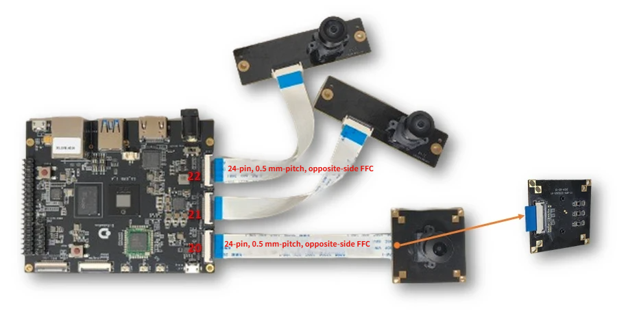
The figure above shows the interfaces on the X5 EVB development board. The corresponding hardware IO resources for each interface are listed below:
| Interface | MIPI CSI Host | Max Supported Lanes | I2C Bus | Reset GPIO | LPWM/PWD | MCLK |
|---|---|---|---|---|---|---|
| 20 | MIPI_CSI0&1 | 4 lanes | I2C4 | AON_GPIO_PIN0 - 498 | LSIO_SPI5_SCLK - lpwm0 | LSIO_SPI3_SCLK - mclk0 |
| 21 | MIPI_CSI2 | 2 lanes | I2C2 | AON_GPIO_PIN4 - 502 | LSIO_SPI5_SSN - lpwm1 | LSIO_SPI3_MISO - mclk2 |
| 22 | MIPI_CSI3 | 2 lanes | I2C7 | LSIO_GPIO1_06 - 353 | LSIO_SPI5_MISO - lpwm2 | LSIO_SPI3_MOSI - mclk3 |
X5 MIPI HOST (RX) system supports the following configurations:
Single Host Mode: Each Host (0-3) independently supports 2 lanes
Lane Stitching Mode: Host0+Host1, Host2+Host3 can be stitched into 4 lanes respectively; EVB defaults to Host0+Host1 stitching, Host2/Host3 as single Host.
5.17.2.4. Steps to Bring Up a New Sensor
When adapting a new camera on the X5 platform, complete the following steps (for specific operations and examples, see each manufacturer’s bring-up document):
Modify Platform Device Tree (dts): Configure sensor power GPIO, I2C, MCLK, LPWM according to hardware design.
Add sensor driver code: Implement the
sensor_module_tinterfaces for initialization/de-initialization, stream on/off, power on/off, gain/exposure control, etc.Add camera App code: Configure MIPI, SIF, camera sensor, LPWM, ISP parameters.
Add default camera ISP tuning library: Prepare
sensor_name_tuning.jsonfor ISP sample programs.Run sample programs: Use get_vin_data / get_isp_data to verify raw image, frame rate, and ISP image meet expectations.
ISP image debug preview: Connect hbplayer to verify driver gain and exposure control, and set up ISP debugging environment.
5.17.2.5. Modify Platform Device Tree (dts)
The device tree should select the corresponding dts file based on actual hardware, for example: kernel/arch/arm64/boot/dts/hobot/x5-evb.dtsi.
Below is the MIPI_CSI0 configuration for the X5 EVB development board:
// I2C configuration
&i2c4 {
        status = "okay";
};

// LPWM configuration
&lpwm0 {
        status = "okay";
        /* conflict with camera pwd gpio */
        pinctrl-names = "default";
        pinctrl-0 = <&pinctrl_lpwm0_0 &pinctrl_lpwm0_1
                        &pinctrl_lpwm0_2 &pinctrl_lpwm0_3>;
};


// dts: Set GPIO in the corresponding vcon node. Note that vcon port numbers correspond one-to-one with mipi rx port numbers
// vcon0 -- mipi_host0
// ....
// vcon3 -- mipi_host3

&mipi_host0 {
        status = "okay";
        pinctrl-names = "enable", "disable";
        pinctrl-0 = <&pinctrl_sensor0_mclk>; //mclk0
        pinctrl-1 = <&lsio_gpio0_24>;
        snrclk-idx = <0>;  //mclk index
};

&vin_vcon0 {
        status = "okay";
        /* camera sensor
         * reset gpio:	AON_GPIO0_00:	498
         * pwd gpio:	LSIO_GPIO1_00:	347
         */
        pinctrl-names = "default";
        pinctrl-0 = <&aon_gpio_0>;
        gpio_oth = <498>;   //reset gpio
        bus = <4>; //i2c4
        lpwm_chn = <0>;  //open lpwm0 - channel0
};
vcon is the DTS node used by X5 to manage sensor hardware configurations. Configure the following based on hardware connections:
1. Sensor GPIO Configuration
2. Sensor I2C Configuration
3. Sensor MCLK Configuration
4. Sensor LPWM Configuration
1. Sensor GPIO Configuration
GPIO related to sensor timing control is described by the
gpio_othproperty in thevin_vconnode.When only a single GPIO control is needed, simply specify the corresponding GPIO number. For example: gpio_oth = <498>;
When multiple GPIOs are needed for control, list all GPIO numbers sequentially in the gpio_oth property. For example: gpio_oth = <498 386>;
For the mapping between PinName pins and GPIO numbers, refer to the hb_gpioinfo Tool Introduction
&vin_vcon0 {
  ...
        pinctrl-names = "default";
        pinctrl-0 = <&aon_gpio_0>;
        gpio_oth = <498>;   //reset gpio
  ...
};
2. Sensor I2C Configuration
X5 I2C bus number needs to be bound to the MIPI RX port in the DTS vcon.
The EVB configuration above uses I2C4: bus = <4>;
&i2c4 {
        status = "okay";
};

&vin_vcon0 {
        status = "okay";
  ...
        bus = <4>; //i2c4
};
3. Sensor MCLK Configuration
MCLK is the Camera Sensor master clock. If provided by X5, configure pinctrl and
snrclk-idxin the correspondingmipi_hostnode.Note: MCLK defaults to GPIO pin. When snrclk is enabled or a camera program is running, the MIPI driver will switch to the MCLK function via pinctrl.
&mipi_host0 {
        status = "okay";
        pinctrl-names = "enable", "disable";
        pinctrl-0 = <&pinctrl_sensor0_mclk>; //mclk0
        pinctrl-1 = <&lsio_gpio0_24>;
        snrclk-idx = <0>;  //mclk index
};
4. Sensor LPWM Configuration
This needs to be configured when the Camera uses Slave Mode. Enable LPWM in the DTS and configure
lpwm_chnin vcon.When X5 SOC outputs a trigger signal, LPWM functionality must be enabled in the DTS and the corresponding lpwm_chn must be configured. The mapping is as follows:
| LPWM Controller | Channel | Corresponding Pinctrl | Physical Pin | lpwm_chn |
|---|---|---|---|---|
| LPWM0 | 0 | pinctrl_lpwm0_0 |
LSIO_SPI5_SCLK | 0 |
| 1 | pinctrl_lpwm0_1 |
LSIO_SPI5_SSN | 1 | |
| 2 | pinctrl_lpwm0_2 |
LSIO_SPI5_MISO | 2 | |
| 3 | pinctrl_lpwm0_3 |
LSIO_SPI5_MOSI | 3 | |
| LPWM1 | 0 | pinctrl_lpwm1_0 |
LSIO_SPI3_SCLK | 4 |
| 1 | pinctrl_lpwm1_1 |
LSIO_SPI3_SSN | 5 | |
| 2 | pinctrl_lpwm1_2 |
LSIO_SPI3_MISO | 6 | |
| 3 | pinctrl_lpwm1_3 |
LSIO_SPI3_MOSI | 7 |
&lpwm0 {
        status = "okay";
        /* conflict with camera pwd gpio */
        pinctrl-names = "default";
        pinctrl-0 = <&pinctrl_lpwm0_0 &pinctrl_lpwm0_1
                        &pinctrl_lpwm0_2 &pinctrl_lpwm0_3>;
};

 &vin_vcon0 {
         status = "okay";
         ...
         lpwm_chn = <0>;  //open lpwm0 - channel0
 };
5. DTS Verification
DTS configuration can be checked using
hb_gpioinfo. For details, refer to hb_gpioinfo Tool IntroductionBelow are the results of checking pin multiplexing configuration using the hb_gpioinfo command. The configuration results are correct.
# hb_gpioinfo | grep AON_GPIO_PIN0
line  0:        unnamed output                            AON_GPIO_PIN0         498      aon_gpio_0         10 mA
# hb_gpioinfo | grep LSIO_SPI5_SCLK
line  0:        unnamed input                             LSIO_SPI5_SCLK        347      pinctrl_lpwm0_0    2 mA
# hb_gpioinfo | grep LSIO_SPI3_SCLK
line 24:        unnamed input                             LSIO_SPI3_SCLK        403      lsio_gpio0_24      9 mA
With correct DTS configuration and proper hardware sensor connection, manually input commands to provide sensor power and MCLK, then use i2cdetect to detect the module’s I2C address.
echo 498 > /sys/class/gpio/export
echo out > /sys/class/gpio/gpio498/direction
echo 0 > /sys/class/gpio/gpio498/value
sleep 0.1
echo 1 > /sys/class/gpio/gpio498/value
# Take host0/rx0 as an example; replace with the actual MIPI RX port
# Usually 24M clock input; adjust according to actual case
echo 24000000 > /sys/class/vps/mipi_host0/param/snrclk_freq
echo 1 > /sys/class/vps/mipi_host0/param/snrclk_en

i2cdetect -y -r 4
Use
i2cdetectto detect the sensor I2C address. If the correct address is detected, as shown below, it indicates the DTS configuration is correct. Otherwise, check the DTS configuration or follow the I2C Communication Failure steps for troubleshooting.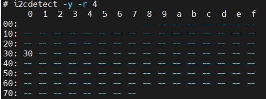
5.17.2.6. Add Sensor Driver Code
Different manufacturers’ sensors come with different styles of drivers. They need to be uniformly adapted to the X5 Camera driver framework.
Driver Location and Naming
Source path:
hbre/camsys/libcam/src/sensor/Deployment path: Copy the compiled
lib<sensor_name>.soto the device’s/usr/hobot/lib/sensor/File naming:
<sensor_name>_utility.c; Structure/module name: consistent with<sensor_name>(e.g., sc132gs, os08c10, imx586, etc.), see each manufacturer’s bring-up for details.
sensor_module_t Interface
1. sensor_module_t Naming Rules
| Item | Naming Requirement | Example |
|---|---|---|
| File name | <sensor_name>_utility.c |
sc132gs_utility.c |
| Structure name | <sensor_name> |
sc132gs |
| Module field | <sensor_name> |
"sc132gs" |
2. sensor_module_t Interface Implementation
The driver must implement sensor_module_t and the following interfaces:
| Function Interface | Description | Invocation Timing |
|---|---|---|
init |
Sensor initialization, setting delivery | hbn_camera_attach_to_vin |
deinit |
Sensor de-initialization | hbn_camera_destroy / hbn_camera_detach_from_vin |
start |
Sensor stream on | hbn_vflow_start |
stop |
Sensor stream off | hbn_vflow_stop |
power_on |
Sensor power on | hbn_camera_attach_to_vin |
power_off |
Sensor power off | hbn_camera_destroy / hbn_camera_detach_from_vin |
aexp_gain_control |
Gain control | ISP algorithm call |
aexp_line_control |
Exposure control | ISP algorithm call |
userspace_control |
User callback control switches (AE/AWB/AF, etc.) | User control |
3. 3A Control
For 3A control, i.e., userspace_control, the X5 system supports two methods: driver registration and application-layer callbacks. The default method is application-layer callback, with the following interface definitions:
| Function | Description | Input Parameters |
|---|---|---|
aexp_gain_control |
Sensor gain control | info: sensor bus information mode: sensor operating mode; linear/hdr/pwl again: sensor again parameters, up to 4 dgain: sensor dgain parameters, up to 4 gain_num: number of sensor gain parameters |
aexp_line_control |
Sensor exposure control | info: sensor bus information mode: sensor operating mode; linear/hdr/pwl line: sensor line parameters, up to 4 line_num: number of sensor line parameters |
awb_control |
Sensor-side AWB control | info: sensor bus information mode: sensor operating mode; linear/hdr/pwl rgain: sensor rgain bgain: sensor bgain grgain: sensor grgain gbgain: sensor gbgain |
userspace_control |
HAL layer control switches | port: sensor port number enable: enable user callback control switch, default all off bit definitions: - HAL_LINE_CONTROL 0x00000001- HAL_GAIN_CONTROL 0x00000002- HAL_AWB_CONTROL 0x00000004 |
Key Concepts
vts/framelength: Total number of lines per frame (active lines + blanking lines). Different sensors may use different names. This is the core parameter for calculating exposure/line time.
lines_per_second: Total number of exposed lines per second, calculated as 1/line_time or fps * vts.
Gain LUT table: Mapping table between ISP 3A algorithm output gain index values and sensor hardware register values, divided into analog gain and digital gain, with a total of 256 control points (index 0-255). This mapping table needs to be generated by the user; examples for different manufacturers will be provided later.
Gain ratio conversion: The actual ratio corresponding to all gain index values (X) is calculated using the formula 2^(X/32), with a logarithmic control curve.
digital_gain_max/analog_gain_max: Maximum gain ratio index values for d_gain/a_gain.
exposure_time_min/exposure_time_max: Minimum/maximum short exposure lines per frame, respectively.
exposure_time_long_max: Maximum long exposure lines per frame, used for HDR sensors.
Sensor initial gain/exposure values, used by the ISP AE algorithm, affecting the brightness of the first few frames. If you care about the brightness of the first few frames, configure these values as the index and exposure line count from the sensor setting’s initial register values.
analog_gain_init: Sensor analog gain initial value. Optional configuration.
digital_gain_init: Sensor digital gain initial value. Optional configuration.
exposure_time_init: Sensor exposure initial value. Optional configuration.
Bayer format: The raw image pixel arrangement mode output by the sensor. Core parameters include
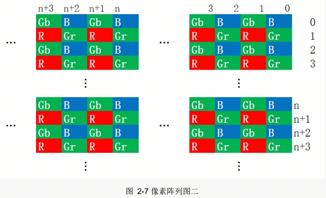
bayer_pattern(pixel arrangement type, such as RGGB/RCCC/RIrGB/RGIrB) andbayer_start(starting pixel in RGGB mode, such as R/Gr/Gb/B). Generally described in the sensor spec.In Bayer mode, each pixel on the image sensor has a color filter that only allows specific colors of light to pass through. The filters are arranged in a specific pattern. Taking sc230ai as an example, where
bayer_startis B at (0,0):
Gain LUT Table Generation Method
To quickly generate gain_lut tables, X5 provides a gain_table.xlsx spreadsheet. Simply fill in the formula for deriving register values from gain ratios in cell C4 to quickly generate the gain_lut table.
The gain_lut table is generally applicable to OmniVision sensors (gain control typically uses integer + fractional linear combination) and Sony sensors (gain control typically uses a linear formula).
SmartSens sensor gain control generally uses discrete steps + fine adjustment. Lookup tables are typically the fastest approach and do not require the gain_table.xlsx spreadsheet.
The gain_table.xlsx spreadsheet is located in the system BSP source package at hbre/camsys/libcam/src/sensor
Driver Deployment Process
Execute
./bd.sh hbre camsys/libcamto compile the sensor library.Copy the generated
lib<sensor_name>.so.*fromout/deploy/hbre/lib/sensorto/usr/hobot/lib/sensor/on the board.
For specific implementations by each sensor manufacturer (init/start/stop/power, linear_data_init, gain_lut generation, aexp_gain/line/userspace_control), please refer to:
5.17.2.7. Add Camera App Code
Refer to app/samples/platform_samples/vp_sensors in the BSP to configure MIPI, SIF, camera sensor, LPWM, ISP, etc. Fill in vp_sensor_config_t according to the sensor’s resolution, frame rate, and data format.
Source path:
app/samples/platform_samples/vp_sensorsDeployment: Copy the compiled get_vin_data, get_isp_data, etc. to the device (e.g.,
/userdata) for testing. For compilation methods, see Sample Development Guide.
vp_sensor_config_t Configuration Items
The vp_sensor_config_t parameter configuration mainly includes: MIPI configuration, camera sensor configuration, SIF configuration, LPWM configuration, and ISP configuration. For details, refer to Data Structures.
5.17.2.8. Add Default Camera ISP Tuning Library
Board-side tuning library path:
/usr/hobot/lib/sensor/<sensor_name>_tuning.jsonYou can first copy a JSON file with the same resolution from the same directory and change the sensor_name to the current sensor as the default tuning library.
5.17.2.9. Board-Side Sample Program Execution
get_vin_data: Check raw image quality and frame rate, confirm no severe color cast and colors match reality. For usage, see sample_vin program execution method.
get_isp_data: Check YUV image, confirm no severe color cast or color inversion; fine-tuning of image quality is done through ISP tuning. For usage, see sample_isp program execution method.
5.17.2.10. ISP Image Debug Preview and 2A Verification
After successfully running get_vin_data / get_isp_data, you can connect hbplayer to preview YUV and use tuning_tool for ISP debugging. For details, see hbplayer and tuning_tool Usage Guide.
2A Verification (AE/AWB): Confirm that the exposure and gain registers written to the sensor comply with the spec; switch AE to Manual and set aGain, dGain, and integrationTime, then verify through driver printout or i2ctransfer register reading.
5.17.2.11. Summary
This document is a general overview of Camera debugging: prepare hardware and software resources -> configure DTS -> implement and deploy sensor driver -> configure and run App -> prepare tuning library -> board-side raw/ISP capture -> ISP preview and 2A verification.
Read the corresponding chapter for your sensor manufacturer for coherent, actionable driver/App/verification instructions; for I2C, MCLK, MIPI, Sensor issues, see Camera Sensor FAQ.