5.17.3. OmniVision Sensor Bring-Up
This document uses os08c10 as an example to describe the complete process of adapting OmniVision series Camera Sensors on the X5 platform
The process includes driver implementation, App configuration, and program verification. For general concepts and DTS configuration, please first read the Camera Debugging Guide.
Source Code Location
Driver interface implementation:
hbre/camsys/libcam/src/sensor/os08c10/os08c10_setting.cGain table and setting configuration:
hbre/camsys/libcam/src/sensor/os08c10/inc/os08c10_setting.h(gain_lut, init/stream_on/stream_off register arrays)
5.17.3.1. DTS Configuration
For DTS configuration, power-on, and sensor ID verification, refer to Modify Platform Device Tree
5.17.3.2. Driver
sensor_module_t and File Naming
File name:
os08c10_utility.c; structure/module name:os08c10; library name:libos08c10.so.1.0.0, deployed to/usr/hobot/lib/sensor/on the board.Required interfaces: init, deinit, start, stop, power_on, power_off, aexp_gain_control, aexp_line_control, userspace_control.
#ifdef CAMERA_FRAMEWORK_HBN
SENSOR_MODULE_F(os08c10, CAM_MODULE_FLAG_A16D8);
sensor_module_t os08c10 = {
        .module = SENSOR_MNAME(os08c10),
#else
sensor_module_t os08c10 = {
        .module = "os08c10",
#endif
        .init = sensor_init,
        .start = sensor_start,
        .stop = sensor_stop,
        .deinit = sensor_deinit,
        .power_on = sensor_poweron,
        .power_off = sensor_poweroff,
        .aexp_line_control = sensor_aexp_line_control,
        .aexp_gain_control = sensor_aexp_gain_control,
        .userspace_control = sensor_userspace_control,
};
power_on
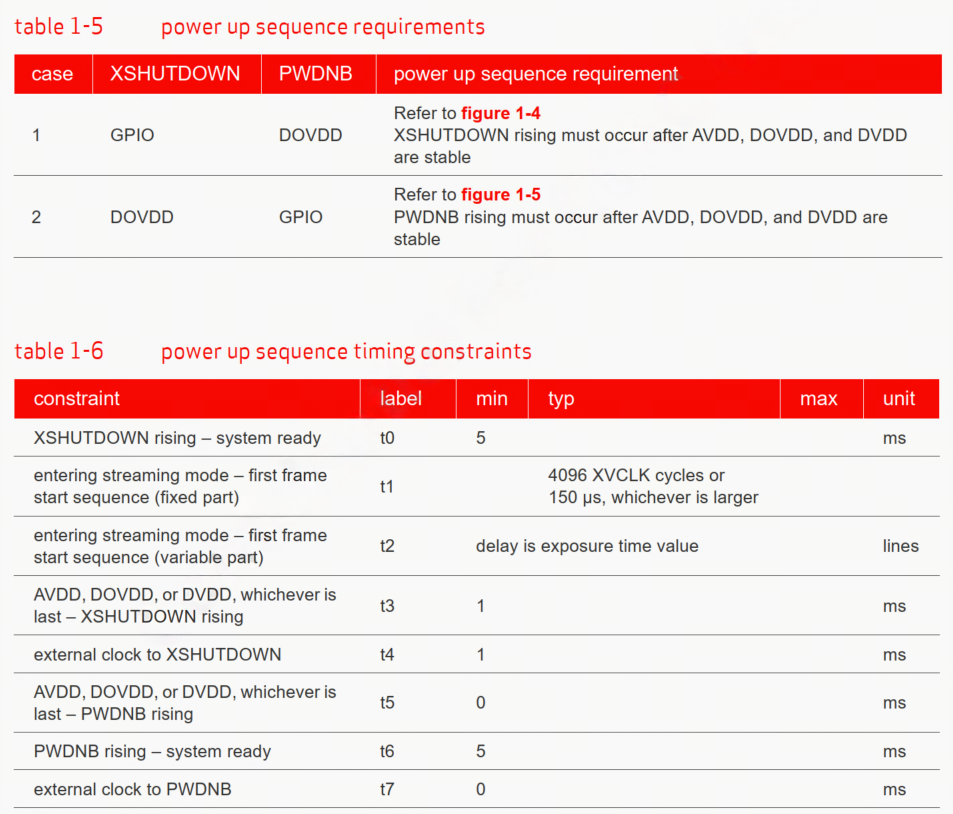
power_on controls sensor power-on via X5 GPIO, following the spec power-up timing.
sensor_poweron is typically called in sensor_init and only needs to control XSHUTDOWN. Below is the power_on implementation for os08c10:
int sensor_poweron(sensor_info_t *sensor_info)
{
        int gpio, ret = RET_OK;
        vin_dbg("%s gpio_num = %d \n", sensor_info->sensor_name, sensor_info->gpio_num);
        if(sensor_info->gpio_num > 0) {
                for(gpio = 0; gpio < sensor_info->gpio_num; gpio++) {
                        vin_dbg("%s gpio_pin[%d] = %d \n", sensor_info->sensor_name, gpio, sensor_info->gpio_pin[gpio]);
                        if(sensor_info->gpio_pin[gpio] != -1) {
                                ret = vin_power_ctrl(sensor_info->gpio_pin[gpio],
                                                sensor_info->gpio_level[gpio]);
                                usleep(100 * 1000);  // 100ms
                                ret |= vin_power_ctrl(sensor_info->gpio_pin[gpio],
                                                1 - sensor_info->gpio_level[gpio]);
                                if(ret < 0) {
                                        vin_err("vin_power_ctrl fail\n");
                                        return -HB_CAM_SENSOR_POWERON_FAIL;
                                }
                                usleep(100 * 1000);  // 100ms
                        }
                }
        }
        return ret;
}
power_off
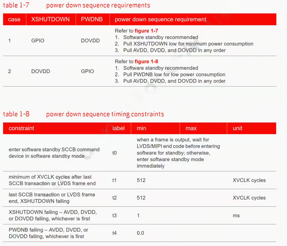
power_off controls sensor power-off via X5 GPIO, following the spec power-down timing.
sensor_poweroff is typically called in sensor_deinit and only needs to control XSHUTDOWN. Below is the power_off implementation for os08c10:
int sensor_poweroff(sensor_info_t *sensor_info)
{
        int gpio, ret = RET_OK;
        if(sensor_info->gpio_num > 0) {
                for(gpio = 0; gpio < sensor_info->gpio_num; gpio++) {
                        if(sensor_info->gpio_pin[gpio] != -1) {
                                ret = vin_power_ctrl(sensor_info->gpio_pin[gpio],
                                                                        sensor_info->gpio_level[gpio]);
                                if(ret < 0) {
                                        vin_err("vin_power_ctrl fail\n");
                                        return -1;
                                }
                        }
                }
        }
        return ret;
}
init
Writes the sensor initialization register list to the sensor via the I2C write function; different resolutions use different setting arrays
os08c10_linear_data_init is used to populate turning_data information.
sensor_init is called when hbn_camera_attach_to_vin is invoked
int sensor_init(sensor_info_t *sensor_info)
{
        int ret = RET_OK;
        int setting_size = 0;

        pr_debug("os08c10 sensor_init \n");
        ret = sensor_poweron(sensor_info);
        if (ret < 0) {
                pr_err("%d : sensor reset %s fail\n", __LINE__, sensor_info->sensor_name);
                return ret;
        }

        if (sensor_info->resolution == 2160) {
                pr_debug("os08c10 resolution is 2160 \n");
                setting_size = sizeof(os08c10_3840x2160_30fps_27MHz_linear_12bit_1701Mbps_2lane) / sizeof(uint32_t) / 2;
                ret = vin_write_array(sensor_info->bus_num, sensor_info->sensor_addr, 2,
                                setting_size, os08c10_3840x2160_30fps_27MHz_linear_12bit_1701Mbps_2lane);
                if (ret < 0) {
                        pr_err("%d : init %s fail\n", __LINE__, sensor_info->sensor_name);
                        return ret;
                }
        } else {
                pr_err("config mode is err\n");
                return -RET_ERROR;
        }

        ret = os08c10_linear_data_init(sensor_info);
        if (ret < 0) {
                pr_err("%d : turning data init %s fail\n", __LINE__, sensor_info->sensor_name);
                return ret;
        }
        return ret;
}
deinit
deinit is typically called for sensor de-initialization; simply call power_off to power down.
sensor_deinit is called when hbn_camera_destroy or hbn_camera_detach_from_vin is invoked.
int sensor_deinit(sensor_info_t *sensor_info)
{
        int ret = RET_OK;
        ret = sensor_poweroff(sensor_info);
        if (ret < 0) {
                pr_err("%d : deinit %s fail\n", __LINE__, sensor_info->sensor_name);
                return ret;
        }
        return ret;
}
start
start implements sending the stream-on register 0x0100 as 0x01 to make the sensor start streaming.
sensor_start is called when the upper layer calls hbn_vflow_start.

int sensor_start(sensor_info_t *sensor_info)
{
        int ret = RET_OK;
        int setting_size = 0;

        pr_debug("os08c10 sensor start\n");
        setting_size = sizeof(os08c10_2lane_stream_on_setting) / sizeof(uint32_t) / 2;
        ret = vin_write_array(sensor_info->bus_num, sensor_info->sensor_addr, 2,
                        setting_size, os08c10_2lane_stream_on_setting);
        if (ret < 0) {
                pr_err("start %s fail\n", sensor_info->sensor_name);
                return ret;
        }
        return ret;
}
stop
stop implements sending the stream-off register 0x0100 as 0x00 to make the sensor stop streaming.
sensor_stop is called when the upper layer calls hbn_vflow_stop
int sensor_stop(sensor_info_t *sensor_info)
{
        int ret = RET_OK;
        int setting_size = 0;

        printf("os08c10 sensor stop \n");
        setting_size = sizeof(os08c10_2lane_stream_off_setting) / sizeof(uint32_t) / 2;
        ret = vin_write_array(sensor_info->bus_num, sensor_info->sensor_addr, 2,
                        setting_size, os08c10_2lane_stream_off_setting);
        if (ret < 0) {
                pr_err("stop %s fail\n", sensor_info->sensor_name);
                return ret;
        }
        return ret;
}
ISP Configuration and linear_data_init
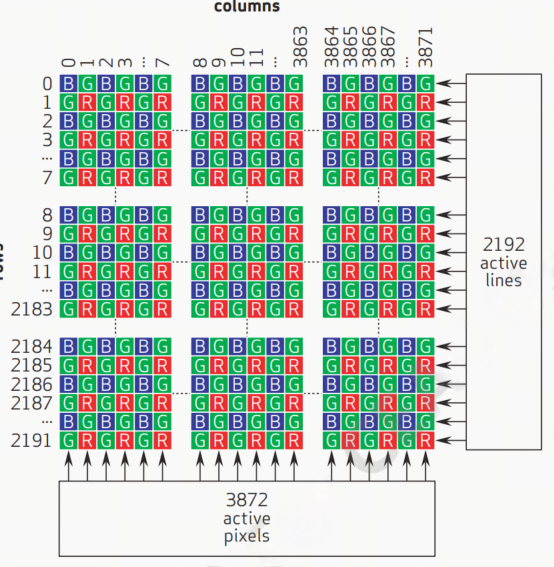
In os08c10_linear_data_init, populate the tuning parameters:
Read VTS from sensor (registers 0x380e/0x380f), calculate lines_per_second;
exposure_time_max/min, analog_gain_max, digital_gain_max;
Populate bayer (sensor_data_bayer_fill, sensor_data_bits_fill);
Set stream_ctrl; copy again_lut from
os08c10_setting.h(os08c10_gain_lut) toturning_data.normal.again_lut, then submit via ioctl.
Key parameter configuration:
lines_per_second = vts * sensor_info->fpsexposure_time_max = vts(max VTS not found in documentation, configured as VTS)analog_gain_max = 191consistent with gain_lut maximum index, 63.5x corresponds to 191, refer to Gain index and gain ratio lookup tabledigital_gain_max = 0dgain unused, configure 0; if used, refer to analog_gain_maxexposure_time_min = 1sensor_data_bayer_fill(..., 12, BAYER_START_B, BAYER_PATTERN_RGGB);sensor_data_bits_fill(..., 12), BAYER_START at position 0,0 is BAYER_START_B, BAYER_PATTERN is RGGB, raw12 format. sensor_data_bits_fill is only used for PWL mode; configure 12 here
aexp_line_control
The aexp_line_control function primarily implements exposure control, responsible for:
Receiving the exposure line count calculated by the ISP 3A algorithm
Converting the exposure line count to sensor register values
Configuring and sending exposure registers to the sensor via I2C
The exposure registers here are 0x3500, 0x3501, 0x3502.
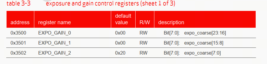
static int sensor_aexp_line_control(hal_control_info_t *info, uint32_t mode, uint32_t *line, uint32_t line_num)
{
        const uint16_t EXP_LINE0 = 0x3500;
        const uint16_t EXP_LINE1 = 0x3501;
        const uint16_t EXP_LINE2 = 0x3502;
        char temp0 = 0, temp1 = 0, temp2 = 0;

        if (mode == NORMAL_M) {
                uint32_t sline = line[0];
                if (sline > 2314) sline = 2314;
                if (sline < 8) sline = 8;

                temp0 = (sline >> 16) & 0xFF;
                vin_i2c_write8(info->bus_num, 16, info->sensor_addr, EXP_LINE0, temp0);
                temp1 = (sline >> 8) & 0x0F;
                vin_i2c_write8(info->bus_num, 16, info->sensor_addr, EXP_LINE1, temp1);
                temp2 = (sline) & 0xFF;
                vin_i2c_write8(info->bus_num, 16, info->sensor_addr, EXP_LINE2, temp2);
        } else {
                vin_err(" unsupport mode %d\n", mode);
        }
        return 0;
}
aexp_gain_control:
The aexp_gain_control function primarily implements gain control, responsible for:
Receiving the gain index value calculated by the ISP 3A algorithm
Looking up the gain_lut table to find the sensor register value based on the gain index
Configuring and sending gain registers to the sensor via I2C
gain_lut generally needs to be configured according to the spec.
For OmniVision sensors, gain control generally uses an integer + fractional linear combination. Taking os08c10 as an example, you need to derive the register value calculation formula based on the gain ratio. The specific method is as follows:
Reference documentation and gain_table.xlsx:


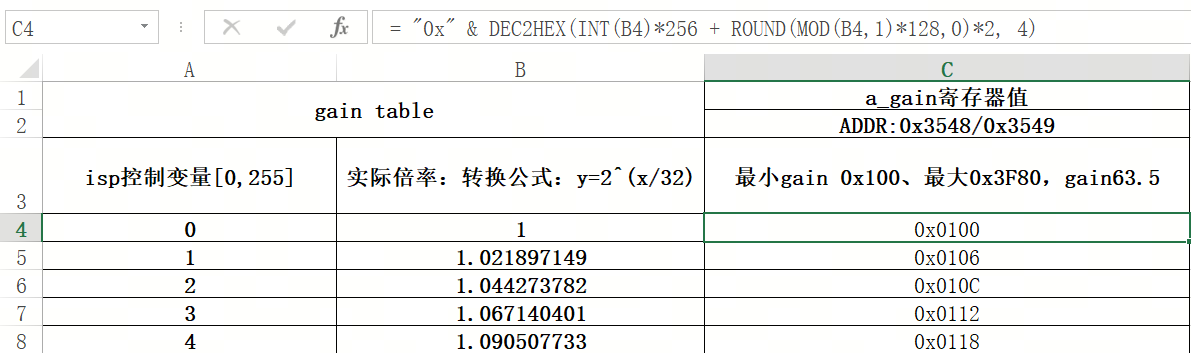
= "0x" & DEC2HEX(INT(B4)*256 + ROUND(MOD(B4,1)*128,0)*2, 4)
Formula explanation:
INT(B4): Get the integer part
MOD(B4,1): Get the fractional part (equivalent to B4-INT(B4))
*128: Convert to 1/128 units
ROUND(...,0): Round to integer
*2: Left shift by 1 bit (because it needs to be placed in the upper 7 bits)
*256: Shift integer part to high byte
DEC2HEX(...,4): Convert to 4-digit hexadecimal
static int sensor_aexp_gain_control(hal_control_info_t *info, uint32_t mode, uint32_t *again, uint32_t *dgain, uint32_t gain_num)
{
        const uint16_t AGAIN_H = 0x3548;
        const uint16_t AGAIN_L = 0x3549;
        char again_reg_value_h = 0, again_reg_value_l = 0;
        int gain_index = 0;

        if (mode == NORMAL_M) {
                if (again[0] >= sizeof(os08c10_gain_lut)/sizeof(uint32_t))
                        gain_index = sizeof(os08c10_gain_lut)/sizeof(uint32_t) - 1;
                else
                        gain_index = again[0];

                again_reg_value_h = (os08c10_gain_lut[gain_index] >> 8) & 0x7F;
                again_reg_value_l = (os08c10_gain_lut[gain_index]) & 0xFE;

                vin_i2c_write8(info->bus_num, 16, info->sensor_addr, AGAIN_H, again_reg_value_h);
                vin_i2c_write8(info->bus_num, 16, info->sensor_addr, AGAIN_L, again_reg_value_l);
        } else {
                vin_err(" unsupport mode %d\n", mode);
        }
        return 0;
}
userspace_control
sensor_userspace_control is used for Gain Control and Exposure Control switches.
When debugging with hbplayer to troubleshoot flicker or image abnormalities, you can enable/disable HAL_GAIN_CONTROL / HAL_LINE_CONTROL to confirm the issue.
static int sensor_userspace_control(uint32_t port, uint32_t *enable)
{
        vin_info("enable userspace gain control and line control\n");
        *enable = HAL_GAIN_CONTROL | HAL_LINE_CONTROL;
        return 0;
}
Driver Deployment
Compile with
./bd.sh hbre camsys/libcam.Copy
out/deploy/hbre/lib/sensor/libos08c10.so.1.0.0to/usr/hobot/lib/sensor/on the board.
5.17.3.3. App Configuration
In the path
app/samples/platform_samples/vp_sensors/os08c10/, add configuration for os08c10.Configure mipi (lane, datatype, mipiclk, linelength, framelength, settle), camera (name, addr, sensor_mode, gpio, fps, width, height, format), vin_node_attr (mipi_rx, cim_isp_flyby, etc.), vin_ichn_attr, vin_ochn_attr (wstride, etc.), isp_attr, isp_ichn_attr, isp_ochn_attr.
HTS/VTS can be read from registers 0x380c/0x380d and 0x380e/0x380f, or obtained from the sensor FAE, or measured with an oscilloscope. For measurement methods, refer to MIPI parameter determination
mipiclk can generally be obtained from the sensor FAE. For calculation methods, refer to MIPI CLK
Other configurations are generic; refer to the Data Structures documentation for configuration.
vp_sensor configuration file: linear_3840x2160_raw10_30fps_2lane.c
Configuration file path:
os08c10/linear_3840x2160_raw10_30fps_2lane.c.Configuration structure name:
os08c10_linear_3480x2160_raw12_30fps_2lane(must be registered in vp_sensor_config_list).The current example uses RAW12 output; datatype/format is configured as 0x2C. Main parameters are as follows:
| Configuration Item | Parameter Name / Location | Value Description |
|---|---|---|
| Top-level | config_file |
"linear_3840x2160_raw12_30fps_2lane.c" |
sensor_name |
"os08c10-30fps-2lane" |
|
chip_id_reg / chip_id |
0x300A / 0x53 | |
sensor_i2c_addr_list |
{0x21} | |
support_sensor_mode |
{NORMAL_M} | |
| MIPI | lane |
2 |
datatype |
RAW12 (0x2C) | |
fps |
30 | |
mipiclk |
1701 (Mbps) | |
width / height |
3840 / 2160 | |
linelength / framelength |
4860 / 2314 (refer to sensor HTS/VTS) | |
settle |
0 (adjust 0-120 if MIPI errors occur) | |
channel_num |
1 | |
| Camera | name / addr |
"os08c10" / 0x21 |
sensor_mode |
1 (NORMAL_M) | |
format |
RAW12 | |
gpio_enable_bit / gpio_level_bit |
0x01 / 0x00 | |
calib_lname |
"disable" | |
| VIN | mipi_rx |
0 |
cim_isp_flyby |
0 (offline) | |
hdr_mode |
NOT_HDR | |
mclk_freq (vin_attr_ex) |
27000000 (27MHz) | |
| VIN Output | wstride |
SENSOR_WIDTH * 2 (RAW12 is x2) |
| ISP Input | input_mode |
DDR_MODE |
sensor_mode |
ISP_NORMAL_M | |
crop |
x=0, y=0, w=3840, h=2160 | |
input_fmt |
FRM_FMT_RAW | |
input_bit_width |
12 | |
| ISP Output | output_fmt |
FRM_FMT_NV12 |
output_bit_width |
8 | |
ddr_en |
1 |
5.17.3.4. Program Verification
sample_vin: Run get_vin_data to confirm raw image has no severe color cast and frame rate is normal; calculate and print the actual frame rate to verify the configured frame rate is correct.
sample_isp: Copy a tuning.json with the same resolution as
os08c10_tuning.jsonand changesensor_nametoos08c10. Run get_isp_data to confirm YUV is normal.hbplayer: Connect to the board to preview YUV, see hbplayer and tuning_tool Usage Guide.
tuning_tool: After connecting to hbplayer using tuning_tool, enter command e, configure Manual AE, set aGain and integrationTime. Check driver printout to verify registers 0x3508/0x3509 and 0x3500~0x3502 match the spec. ISP gain limits can be configured in os08c10_tuning.json for self-testing.
For common issues, see Camera Sensor FAQ.