5.17.7. Camera Debugging FAQ
Below are common sensor error codes and simple troubleshooting directions:
| Error Code | Definition | Troubleshooting Direction |
|---|---|---|
| 203 | HB_CAM_INIT_FAIL | Sensor initialization failed, generally due to I2C communication failure or unsupported configured sensor mode |
| 205 | HB_CAM_START_FAIL | Sensor start failed, generally due to I2C communication failure or unsupported configured sensor mode |
| 207 | HB_CAM_I2C_WRITE_FAIL | Sensor I2C communication failure, refer to I2C Communication Failure |
| 217 | HB_CAM_SENSOR_POWERON_FAIL | Sensor power-on failed, possibly due to incorrect sensor GPIO configuration |
| 218 | HB_CAM_SENSOR_POWEROFF_FAIL | Sensor power-off failed, possibly due to incorrect sensor GPIO configuration |
5.17.7.1. FAQ
Below are common problems and solutions during the sensor bring-up process:
Table of Contents
| Category | Problem | Link |
|---|---|---|
| I2C | I2C communication failure | I2C Communication Failure |
| MCLK | How to modify MCLK drive current | How to modify MCLK drive current |
| MCLK | Check MCLK frequency and enable status | Check MCLK frequency and enable status |
| MIPI | Unable to enter HS, MIPI start error | Unable to enter HS, MIPI start error |
| MIPI | MIPI error | MIPI error |
| MIPI | MIPI parameter determination | MIPI parameter determination |
| MIPI | How to modify MIPI drive current | How to modify MIPI drive current |
| MIPI | How to check HOST(RX) device current running status and configuration | How to check HOST(RX) device current running status and configuration |
| MIPI | How to check HOST(RX) device registers | How to check HOST(RX) device registers |
| MIPI | How to configure multiple VC sensor modules on the same HOST RX | How to configure multiple VC sensor modules on the same HOST RX |
| MIPI | How to enable MIPI driver logging | How to enable MIPI driver logging |
| Sensor | Sensor library check or load error | Sensor library check or load error |
| Sensor | Sensor slave mode configuration | Sensor slave mode configuration |
| Image | Dumped image has vertical stripe artifacts | Dumped image has vertical stripe artifacts |
| Gain | Gain index and gain ratio lookup table | Gain index and gain ratio lookup table |
| VTunerClient | Connecting VTunerClient | Connecting VTunerClient |
| VTunerClient | How to use VTunerClient to verify 2A | How to use VTunerClient to verify 2A |
5.17.7.2. I2C
I2C Communication Failure
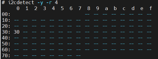
Use the i2cdetect command to detect the bus ID. If the sensor on the I2C bus can be detected, it indicates the sensor is properly connected, as shown below:
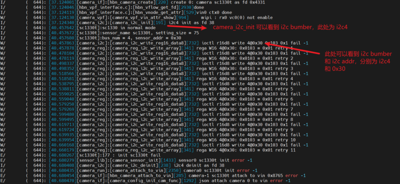
Through logcat, you can see sensor init error and I2C communication failure related logs:
Troubleshooting Methods:
Hardware Troubleshooting:
Check if the camera module is properly connected
Check GPIO configuration:
Reset GPIO
PWD (sensor xshutdown) GPIO
Power_en GPIO
MCLK
Use a multimeter and oscilloscope to measure and eliminate issues one by one
Check module power supply:
Check the module pin list or schematic
Measure the power supply situation, which may include 3.0V/2.8V/1.8V/1.2V, etc.
Check I2C signals:
Ensure I2C SDA and SCLK are pulled up, usually to 1.8V
Default SCLK is 100K, ensure it meets the sensor I2C speed requirements, otherwise modify the DTS I2C default speed
Check MCLK:
Ensure the MCLK (sensor extclk) pin has a waveform, usually 24M or 27M
Check power-up sequence:
Ensure the sensor power-up sequence meets the sensor spec requirements
Software Troubleshooting:
Check I2C configuration:
Whether the I2C number matches the actual hardware configuration
Whether the I2C address matches the actual hardware configuration
Check DTS binding:
X5 MIPI host and I2C number are bound in the DTS
For example, MIPI host0 uses I2C number 4, must ensure the DTS-bound bus matches the actual hardware
5.17.7.3. MCLK
How to modify MCLK drive current
MCLK defaults to GPIO pin. When snrclk is enabled or a camera program is running, the MIPI driver will select the MCLK function pin via pinctrl.
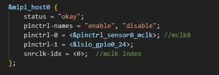
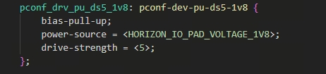
To adjust MCLK drive current, modify the driver-strength of the corresponding MCLK pin.

Check MCLK frequency and enable status
cat /sys/class/vps/mipi_host0/status/snrclk
snrclk         : sensor0_mclk
support        : enable disable
state          : enable # Current status: enable
freq           : 24000000
5.17.7.4. MIPI
Unable to enter HS, MIPI start error
MIPI unable to enter HS mode may have several possible causes:
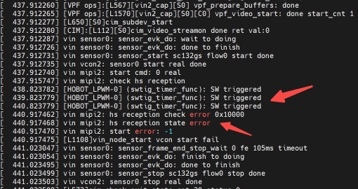
Possible Causes:
1. Sensor not streaming normally
Slave mode:
The sensor is in slave mode and requires an external trigger signal to stream normally
Check the trigger signal configuration and measure whether the trigger signal is being generated
Master mode:
Sensor start automatically calls register writes to the sensor and actively starts streaming
Use an oscilloscope to measure the MIPI data lane to confirm data presence
If no data is present, confirm that the stream_on_setting registers are configured correctly
2. Sensor streaming prematurely
The sensor settings may contain streaming configuration, causing the sensor to start streaming automatically after initialization
This situation does not meet X5 MIPI timing requirements. The streaming configuration in the sensor settings must be commented out, and streaming should be initiated in sensor_start
static uint32_t sc230ai_linear_init_setting[] = {
    ....
    // 0x0100,0x01,  // Do not include stream-on configuration at the end of the settings
}
static uint32_t sc230ai_stream_on_setting[] = {
    0x0100,0x01,
};
If the sensor characteristic requires that there must be a streaming configuration in the sensor setting, the HS check needs to be manually skipped
Methods to skip HS check:
Temporary debugging (shell command):
# Note: Replace the mipi host with the corresponding port number
echo 1 > /sys/class/vps/mipi_host0/param/stop_check_instart
Integrated into code:
static mipi_config_t mipi_config = {
	.rx_enable = 1,
	...
	.rx_ex_mask = 0x40,
	.rx_attr_ex = {
		.stop_check_instart = 1,
	}
};
MIPI error
MIPI PHY Fatal Error
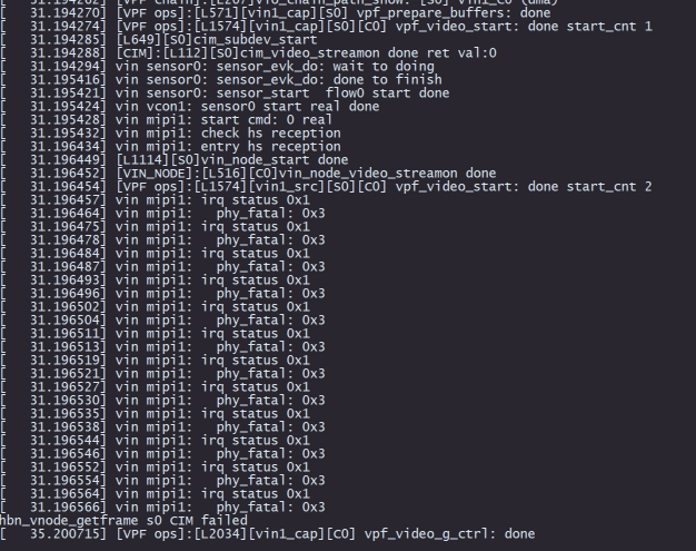
MIPI PHY fatal error is a physical layer error, indicating transmission issues between the sensor and X5 MIPI PHY. Possible causes are as follows:
MIPI clock configuration is incorrect, see MIPI parameter determination
MIPI settle configuration is incorrect, see MIPI parameter determination
MIPI parameter determination
Framelength (VTS)
Definition:
Frame length, representing the number of rows exposed per frame by the camera
Includes the active height and vertical blanking (VBlank) rows
How to obtain:
Register read (recommended):
The sensor spec generally provides registers for reading frame length
After sensor initialization, read this register and print the value
Oscilloscope measurement:
If the sensor spec does not provide this information, actual measurement on the MIPI data pins is required. A typical oscilloscope measurement is shown below:
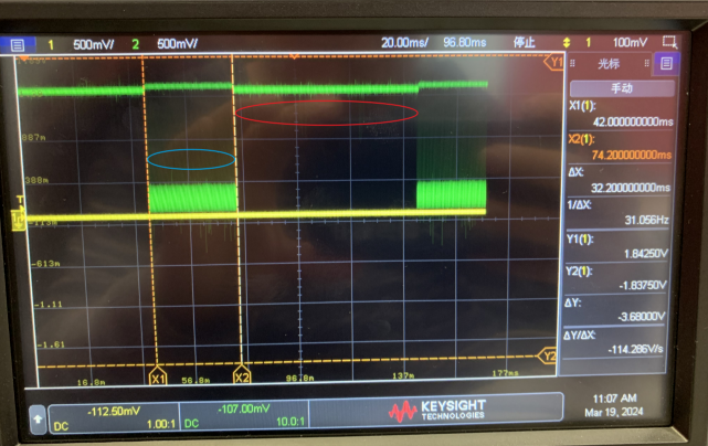
Blue circle indicates valid signal: 32ms; red circle indicates blanking signal, duration: 68ms; total duration: 100ms
Image height is 1080, so transmitting 1080 pixels takes 32ms. Including blanking pixels, framelength can be calculated as:
framelength = 1080 * 100 / 32 = 3375
Linelength (HTS)
Definition:
Line length, representing the number of pixels exposed per line by the camera
Includes the active width and horizontal blanking (HBlank) width
How to obtain:
Register read (recommended):
The sensor spec generally provides registers for reading line length
After sensor initialization, read this register and print the value
Oscilloscope measurement:
If the sensor spec does not provide this information, actual measurement on the MIPI data pins is required. A typical oscilloscope measurement is shown below:
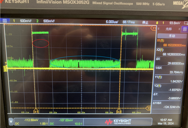
Blue circle shows one line of valid data signal, duration: 24.2us; red circle shows blanking signal, duration: 5.4us; total duration: 24.2 + 5.4 = 29.6us
Image width is 1920, so transmitting 1920 pixels takes 24.2us. Including blanking pixels, linelength can be calculated as:
linelength = 1920 * 29.6 / 24.2 = 2348
MIPI CLK
Description:
The sensor is the MIPI TX side, and the X5 SOC is the MIPI RX side
MIPI clock is determined by the sensor side; configuration values can generally be obtained from the sensor manufacturer’s FAE
Configuration rules:
X5 MIPI clock uses double-edge sampling, which is 2 times the actual physical signal frequency (or oscilloscope-measured frequency)
And is the sum across multiple lanes
Calculation formula:
X5 MIPI clock = 2 * number of lanes * physical clockExample: sensor with 2-lane configuration, physical clock per lane is 500M
Then:
X5 MIPI clock = 2 * 2 * 500M = 2000M, enter 2000 in configurationIf hardware permits, differential probes on an oscilloscope can also be used for measurement
Settle
Definition:
Settle is a concept defined in the MIPI protocol. A brief introduction to the settle signal:
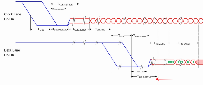
When MIPI transitions from LP to HS state, a transient pulse may appear on the hardware signal
The MIPI receiver needs to delay for the settle time to avoid this pulse before enabling data reception
The SETTLE value consists of the prepare phase and part of the zero signal, as shown above
How to obtain:
1. Use default value:
You can use the default value 0; the MIPI driver will automatically calculate a working settle value
2. Trial-and-error method:
The settle value is in the range [0-120]
If set incorrectly, a MIPI PHY fatal error will occur, similar to the image below:
Therefore, we can use trial and error to find the valid range
During debugging, try values between 0 and 120. If errors occur below a certain value A and also above a certain value B, then settle takes the midpoint of [A, B]
3. Actual measurement method:
Use an oscilloscope to capture the transition from LP to HS on the MIPI data lane (both D+ and D- lanes must be measured simultaneously). Measure the settle duration from the waveform directly. A typical oscilloscope measurement is shown below:
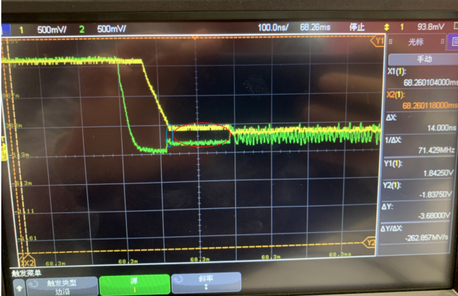
Blue circle: hs-prepare = 14ns
Red circle: hs-zero = 154ns
Unit Interval (UI) = 1s / (MIPI physical single-lane clock / 2) = 1s / (405M / 2) = 4.94 ns
min = prepare / UI = 14 / 4.94 = 3 UI
max = (prepare + zero) / UI = (154 + 14) / 4.94 = 34 UI
settle = (min + max) / 2 = 19 UI
How to modify MIPI drive current
Description:
The X5 SOC side acts as MIPI RX and cannot modify the MIPI drive current
Modification must be done from the MIPI TX side (sensor side); please consult the sensor FAE
How to check HOST(RX) device current running status and configuration
Check running status:
cat /sys/class/vps/mipi_host0/status/info
Check configuration (configuration sent during init):
cat /sys/class/vps/mipi_host0/status/cfg
How to check HOST(RX) device registers
Method:
Register dump via sysfs for debugging convenience
cat /sys/class/vps/mipi_host0/status/regs
How to configure multiple VC sensor modules on the same HOST RX
Prerequisites:
The MIPI TX side (sensor module side) needs to send data through different virtual channels
For example: VC0 sends sensor0 data, VC1 sends sensor1 data
Configuration Steps:
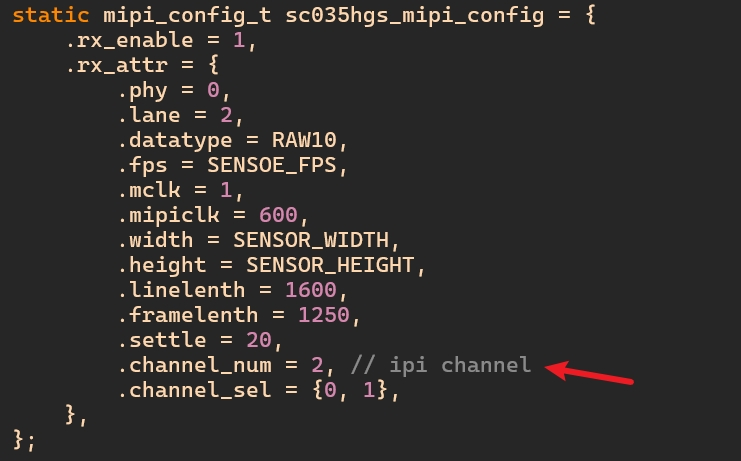
1. MIPI configuration of corresponding channel_num and channel_sel
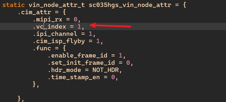
2. VIN configuration of corresponding vc_index
3. Multi-VC output configuration:
If multiple VC outputs are needed, configure multiple pipelines
Each pipeline is configured with the corresponding vc_index separately
How to enable MIPI driver logging
# Replace with the corresponding mipi host port
# Output mipi debug information to pr_debug
echo 1 > /sys/class/vps/mipi_host0/param/dbg_value

# Enable debug for the corresponding files, pr_debug information prints to dmesg and /dev/kmsg
echo "file hobot_mipi_host.c +p" > /sys/kernel/debug/dynamic_debug/control
echo "file hobot_mipi_host_ops.c +p" > /sys/kernel/debug/dynamic_debug/control

# Note: To print to serial console, set the kernel console print level to INFO or above, e.g.:
echo 8 > /proc/sys/kernel/printk
5.17.7.5. Sensor
Sensor library check or load error
Sensor library check error indicates an issue with the sensor driver
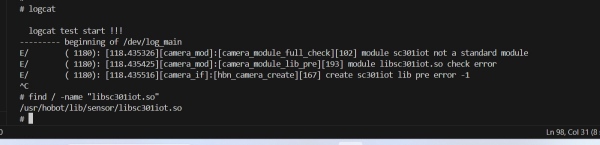
Possible Causes:
1. Compilation issue:
Sensor compiled incorrectly or not compiled properly before being pushed to the board for loading
2. Framework issue:
Compiled correctly but not written according to the HBN framework
The sensor driver must be written following the sensor driver file addition rules
Sensor slave mode configuration
Description:
If the sensor operates in slave mode, it requires an external trigger signal for the sensor to properly expose and output image data
Configuration Key Points:
1. Trigger signal:
Depending on customer requirements, the trigger signal can come from:
The FSYNC output of another sensor operating in master mode
The X5 SOC LPWM pin output signal
For trigger signal requirements (such as high/low levels, minimum pulse width), please consult the sensor manufacturer’s FAE
2. Sensor setting:
When the sensor operates in slave mode, the corresponding init settings must be modified
The power on/power off settings may also need to be modified
Please consult the sensor manufacturer’s FAE
3. Handling without trigger signal:
After configuration, if no trigger signal is present, the sensor cannot output images normally
MIPI may report an error indicating failure to enter HS mode
The MIPI nocheck attribute can be configured as follows:

Alternatively, use the echo command to set the nocheck attribute:
# Example using host0/rx0; replace with the actual MIPI RX port
echo 1 > /sys/class/vps/mipi_host0/param/nocheck
How to configure a YUV sensor?
YUV Data Layout
Planar: Y, U, and V data are stored separately in three distinct planes.
Semi-planar: Y data is stored independently, while U and V data are interleaved in a second plane, forming two planes total.
Packed: YUV data is packed together; individual Y, U, or V components are not stored contiguously.
YUV Naming Convention
YUVxxxP, YUVxxxSP: e.g., YUV422P, YUV420SP. Named according to layout type: P for planar (order: Y first, U middle, V last); SP for semi-planar (order: Y first, UV together afterward).
Ixxx: e.g., I422, I420. Alternative names for planar formats: I422 = YUV422P, I420 = YUV420P.
NVxx, YVxx: e.g., NV12, NV21, NV16, YV12. “NV” indicates semi-planar format; the number indicates bits per pixel. NV12 is YUV420SP: each pixel uses 1 Y (8-bit) + 1/4 UV (8x2 / 4 = 4-bit) = 12 bits total.
To add a YUV sensor, first determine the specific output format. Currently, X5 supports the following formats:
8-bit YUV422SP (semi-planar): Also known as NV16. Y data is stored separately; U and V are interleaved (U before V): YYYYYYY…UVUVUVUV… In sensor and MIPI configuration, set
formatto 0x1E,pack_modeto 2, andstrideto 1x width.8-bit YUV422P (packed): Also known as YUYV422. YUV 4:2:2 sampling with interleaved pixel storage: YUVYUVYUV… In configuration, set
formatto 0x1E,pack_modeto 1, andstrideto 2x width.8-bit YUV420SP (semi-planar): Also known as NV12. Y data is separate; U and V are interleaved (U before V): YYYYYYY…UVUVUVUV… In configuration, set
formatto 0x18,pack_modeto 2, andstrideto 1x width.
For other YUV formats, please contact the sensor manufacturer’s FAE for support.
Note: When connecting a YUV sensor to MIPI, data is directly dumped from SIF to DDR. If downstream modules are needed, bypass the ISP module (since ISP only supports raw input), and directly bind SIF to VSE or other downstream modules. Image quality must be ensured by the sensor module itself, as X5 cannot perform ISP-based tuning on YUV data.
5.17.7.6. Image
Dumped image has vertical stripe artifacts
The image exhibits regular black vertical stripes. The log and image are shown below:
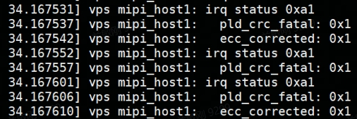
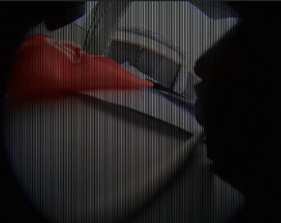
Cause:
The P/N of one DATA LANE group is reversed
MIPI data is split by byte to each lane for transmission, then reassembled and parsed
Any DATA LANE issue will result in a CRC error
If only one LANE has reversed connections, the image will show regular vertical stripes (one abnormal byte value every few bytes)
Solution:
Check hardware connections and confirm that the DATA LANE P/N connections are correct
5.17.7.7. Gain index and gain ratio lookup table
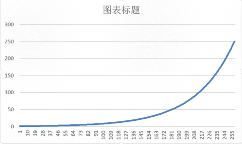
The ISP (Image Signal Processor) 3A (Auto Exposure/Auto White Balance/Auto Focus) algorithms need to control the sensor’s gain. However, ISP and sensor use different gain representations:
ISP gain is expressed as a ratio (e.g., 1x, 2x, 4x, 255x), and converts the ratio to an index value of 0-255 that is passed to the sensor driver
The conversion formula is as follows: x = 32 * log2(gain)
Below is the lookup table for gain index and ISP gain ratio:
| Index (x) | Gain Ratio | Index (x) | Gain Ratio | Index (x) | Gain Ratio | Index (x) | Gain Ratio |
|---|---|---|---|---|---|---|---|
| 0 | 1.000 | 64 | 4.000 | 128 | 16.000 | 192 | 64.000 |
| 1 | 1.022 | 65 | 4.088 | 129 | 16.350 | 193 | 65.401 |
| 2 | 1.044 | 66 | 4.177 | 130 | 16.708 | 194 | 66.834 |
| 3 | 1.067 | 67 | 4.269 | 131 | 17.074 | 195 | 68.297 |
| 4 | 1.091 | 68 | 4.362 | 132 | 17.448 | 196 | 69.792 |
| 5 | 1.114 | 69 | 4.458 | 133 | 17.830 | 197 | 71.321 |
| 6 | 1.139 | 70 | 4.555 | 134 | 18.221 | 198 | 72.882 |
| 7 | 1.164 | 71 | 4.655 | 135 | 18.620 | 199 | 74.478 |
| 8 | 1.189 | 72 | 4.757 | 136 | 19.027 | 200 | 76.109 |
| 9 | 1.215 | 73 | 4.861 | 137 | 19.444 | 201 | 77.776 |
| 10 | 1.242 | 74 | 4.967 | 138 | 19.870 | 202 | 79.479 |
| 11 | 1.269 | 75 | 5.076 | 139 | 20.305 | 203 | 81.219 |
| 12 | 1.297 | 76 | 5.187 | 140 | 20.749 | 204 | 82.998 |
| 13 | 1.325 | 77 | 5.301 | 141 | 21.204 | 205 | 84.815 |
| 14 | 1.354 | 78 | 5.417 | 142 | 21.668 | 206 | 86.672 |
| 15 | 1.384 | 79 | 5.536 | 143 | 22.143 | 207 | 88.570 |
| 16 | 1.414 | 80 | 5.657 | 144 | 22.627 | 208 | 90.510 |
| 17 | 1.445 | 81 | 5.781 | 145 | 23.123 | 209 | 92.492 |
| 18 | 1.477 | 82 | 5.907 | 146 | 23.629 | 210 | 94.517 |
| 19 | 1.509 | 83 | 6.037 | 147 | 24.147 | 211 | 96.587 |
| 20 | 1.542 | 84 | 6.169 | 148 | 24.675 | 212 | 98.701 |
| 21 | 1.576 | 85 | 6.304 | 149 | 25.216 | 213 | 100.863 |
| 22 | 1.610 | 86 | 6.442 | 150 | 25.768 | 214 | 103.071 |
| 23 | 1.646 | 87 | 6.583 | 151 | 26.332 | 215 | 105.328 |
| 24 | 1.682 | 88 | 6.727 | 152 | 26.909 | 216 | 107.635 |
| 25 | 1.719 | 89 | 6.874 | 153 | 27.498 | 217 | 109.992 |
| 26 | 1.756 | 90 | 7.025 | 154 | 28.100 | 218 | 112.400 |
| 27 | 1.795 | 91 | 7.179 | 155 | 28.715 | 219 | 114.861 |
| 28 | 1.834 | 92 | 7.336 | 156 | 29.344 | 220 | 117.377 |
| 29 | 1.874 | 93 | 7.497 | 157 | 29.987 | 221 | 119.947 |
| 30 | 1.915 | 94 | 7.661 | 158 | 30.643 | 222 | 122.573 |
| 31 | 1.957 | 95 | 7.829 | 159 | 31.314 | 223 | 125.257 |
| 32 | 2.000 | 96 | 8.000 | 160 | 32.000 | 224 | 128.000 |
| 33 | 2.044 | 97 | 8.175 | 161 | 32.701 | 225 | 130.803 |
| 34 | 2.089 | 98 | 8.354 | 162 | 33.417 | 226 | 133.667 |
| 35 | 2.134 | 99 | 8.537 | 163 | 34.148 | 227 | 136.594 |
| 36 | 2.181 | 100 | 8.724 | 164 | 34.896 | 228 | 139.585 |
| 37 | 2.229 | 101 | 8.915 | 165 | 35.660 | 229 | 142.642 |
| 38 | 2.278 | 102 | 9.110 | 166 | 36.441 | 230 | 145.765 |
| 39 | 2.327 | 103 | 9.310 | 167 | 37.239 | 231 | 148.957 |
| 40 | 2.378 | 104 | 9.514 | 168 | 38.055 | 232 | 152.219 |
| 41 | 2.430 | 105 | 9.722 | 169 | 38.888 | 233 | 155.552 |
| 42 | 2.484 | 106 | 9.935 | 170 | 39.739 | 234 | 158.958 |
| 43 | 2.538 | 107 | 10.152 | 171 | 40.610 | 235 | 162.439 |
| 44 | 2.594 | 108 | 10.375 | 172 | 41.499 | 236 | 165.995 |
| 45 | 2.650 | 109 | 10.602 | 173 | 42.408 | 237 | 169.630 |
| 46 | 2.709 | 110 | 10.834 | 174 | 43.336 | 238 | 173.345 |
| 47 | 2.768 | 111 | 11.071 | 175 | 44.285 | 239 | 177.140 |
| 48 | 2.828 | 112 | 11.314 | 176 | 45.255 | 240 | 181.019 |
| 49 | 2.890 | 113 | 11.561 | 177 | 46.246 | 241 | 184.983 |
| 50 | 2.954 | 114 | 11.815 | 178 | 47.258 | 242 | 189.034 |
| 51 | 3.018 | 115 | 12.073 | 179 | 48.293 | 243 | 193.173 |
| 52 | 3.084 | 116 | 12.338 | 180 | 49.351 | 244 | 197.403 |
| 53 | 3.152 | 117 | 12.608 | 181 | 50.431 | 245 | 201.726 |
| 54 | 3.221 | 118 | 12.884 | 182 | 51.536 | 246 | 206.143 |
| 55 | 3.292 | 119 | 13.166 | 183 | 52.664 | 247 | 210.657 |
| 56 | 3.364 | 120 | 13.454 | 184 | 53.817 | 248 | 215.269 |
| 57 | 3.437 | 121 | 13.749 | 185 | 54.996 | 249 | 219.983 |
| 58 | 3.513 | 122 | 14.050 | 186 | 56.200 | 250 | 224.800 |
| 59 | 3.589 | 123 | 14.358 | 187 | 57.431 | 251 | 229.723 |
| 60 | 3.668 | 124 | 14.672 | 188 | 58.688 | 252 | 234.753 |
| 61 | 3.748 | 125 | 14.993 | 189 | 59.973 | 253 | 239.893 |
| 62 | 3.830 | 126 | 15.322 | 190 | 61.287 | 254 | 245.146 |
| 63 | 3.914 | 127 | 15.657 | 191 | 62.629 | 255 | 250.514 |
5.17.7.8. VTunerClient
Connecting VTunerClient
Ensure the X5 board and PC are correctly connected via network and can ping each other. The PC command line should be able to SSH into the board.
On the board, execute the following commands to start the tuning service and tuning application:
echo 1 > /sys/kernel/debug/isp/tune
./run_tuning.sh --run 4
Open the tuning tool “VTunerClient” on the PC
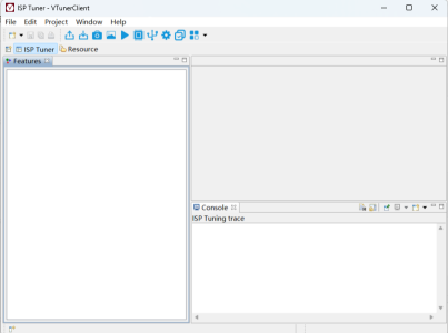
Create a new project
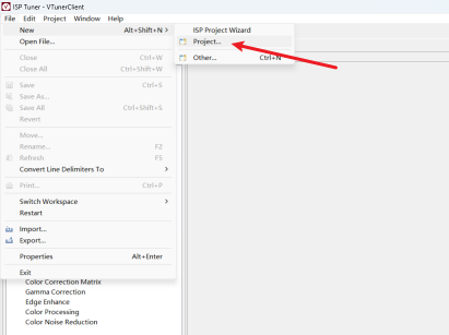
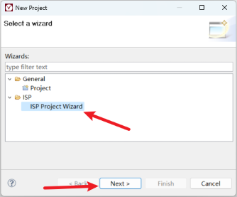
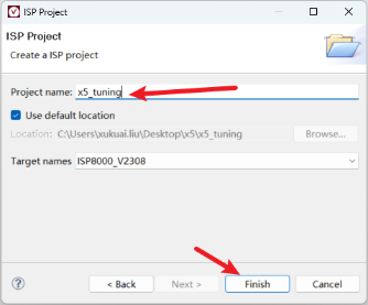
Connect to the board via TCP
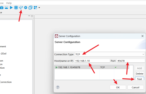
Note: The IP address and port number are fixed. Enter them exactly as shown in the screenshot. Click the Test button; a green checkmark appearing after TCP indicates a successful connection. Then click the OK button.
Connect the project
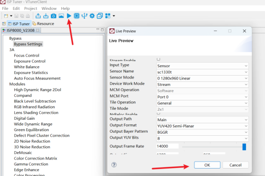
This is simply connecting to the tuning tool. You may select any sensor name here. For actual tuning, create a new sensor option in your project based on the isp_sensor.json file in the project folder.
After completing the above steps, the connection is established, and ISP tuning engineers can begin adjusting sensor performance.
How to use VTunerClient to verify 2A
I. Verification Requirements
AE (Auto Exposure) Confirm that the exposure values and gain registers written to the sensor comply with the specification (Spec) requirements.
AWB (Auto White Balance) If the sensor supports AWB register writing, confirm that the written values comply with the specification requirements.
II. X5 ISP AE Adjustment Mechanism
After the sensor exposes and outputs an image, the SOC ISP receives a frame of data.
The ISP first calculates luminance statistics for that frame.
An AE Target (target luminance value) is preset in ISP Tuning.
If the statistical luminance does not match the AE Target, the ISP AE algorithm calculates new exposure time and gain values, and writes them to the sensor through the driver.
The adjustment continues until the statistical luminance approaches the AE Target.
Changes in ambient brightness trigger this adjustment process again.
III. Practical Verification Steps
Refer to hbplayer and tuning_tool Usage Guide.
Switch AE mode to Manual for observation and control of the adjustment process.
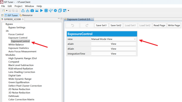
If the Manual Mode View UI appears grayed out, first enter Auto Mode View, click the Disable button, then switch to Manual Mode View:
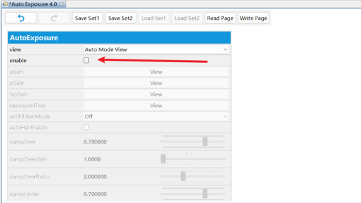
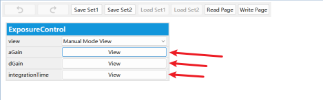
Set aGain, dGain, and integrationTime values manually for verification. For example, set exposure time to 5ms (remember to click Write Page):
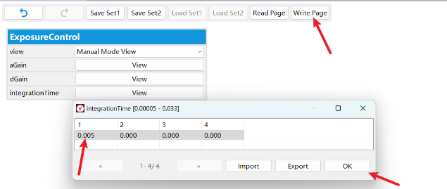
Then verify through sensor driver logging (you need to add logging yourself) or use the i2ctransfer tool to check sensor register values, confirming that the register values written to the sensor comply with the spec requirements.