5.17.6. HDR Sensor Bring-Up
⚠️ Important Notice: When an HDR sensor is connected, the VIN-ISP connection must use online mode. Since online mode exclusively occupies the ISP resource, only 1 stream is supported.
This document uses Sony imx415 DOL2 as an example to describe the complete process of adapting an HDR mode Camera Sensor on the X5 platform.
The Sony sensor HDR implementation outputs image line data with alternating exposure times within one frame set period.
The process includes driver implementation, App configuration, and program verification. For general concepts and dts configuration, please read the Camera Bring-Up Guide first.
Source Code Location
Driver interface implementation:
hbre/camsys/libcam/src/sensor/imx415/imx415_utility.cGain table and Setting configuration:
hbre/camsys/libcam/src/sensor/imx415/inc/imx415_setting.h(gain_lut, init/stream_on/stream_off register arrays)
5.17.6.1. dts Configuration
For dts configuration, power-on, and sensor ID verification, refer to Modify Platform Device Tree
The dts configuration for DOL2 mode is the same as Linear mode, no additional modifications required.
5.17.6.2. Driver
sensor_module_t and File Naming
File name:
imx415_utility.c; struct/module name:imx415; library name:libimx415.so.1.0.0, deployed to/usr/hobot/lib/sensor/on the board.Required interfaces: init, deinit, start, stop, power_on, power_off, aexp_gain_control, aexp_line_control, userspace_control.
HDR mode and Linear mode share the same sensor_module_t, differentiated by
sensor_modeto take different branches.
#ifdef CAMERA_FRAMEWORK_HBN
SENSOR_MODULE_F(imx415, CAM_MODULE_FLAG_A16D8);
sensor_module_t imx415 = {
        .module = SENSOR_MNAME(imx415),
#else
sensor_module_t imx415 = {
        .module = "imx415",
#endif
        .init = sensor_init,
        .start = sensor_start,
        .stop = sensor_stop,
        .deinit = sensor_deinit,
        .power_on = sensor_poweron,
        .power_off = sensor_poweroff,
        .aexp_gain_control = sensor_aexp_gain_control,
        .aexp_line_control = sensor_aexp_line_control,
        .userspace_control = sensor_userspace_control,
};
power_on
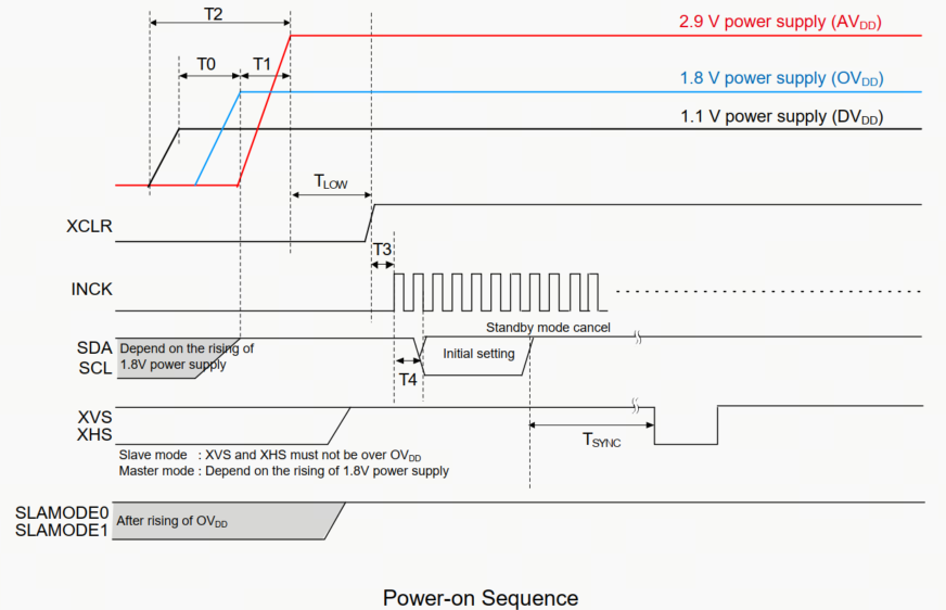
power_on controls sensor power-up through X5 GPIO, following the spec power-on timing sequence.
sensor_poweron is typically called in sensor_init, only XCLR needs to be controlled.
The power-on sequence is identical for HDR mode and Linear mode. The following is the imx415 power_on implementation:
static int sensor_poweron(sensor_info_t *sensor_info)
{
        int gpio, ret = RET_OK;
        vin_dbg("%s gpio_num = %d \n", sensor_info->sensor_name, sensor_info->gpio_num);
        if(sensor_info->gpio_num > 0) {
                for(gpio = 0; gpio < sensor_info->gpio_num; gpio++) {
                        vin_dbg("%s gpio_pin[%d] = %d \n", sensor_info->sensor_name, gpio, sensor_info->gpio_pin[gpio]);
                        if(sensor_info->gpio_pin[gpio] != -1) {
                                ret = vin_power_ctrl(sensor_info->gpio_pin[gpio],
                                                sensor_info->gpio_level[gpio]);
                                usleep(100 * 1000);  // 100ms
                                ret |= vin_power_ctrl(sensor_info->gpio_pin[gpio],
                                                1 - sensor_info->gpio_level[gpio]);
                                if(ret < 0) {
                                        vin_err("vin_power_ctrl fail\n");
                                        return -HB_CAM_SENSOR_POWERON_FAIL;
                                }
                                usleep(100 * 1000);  // 100ms
                        }
                }
        }
        return ret;
}
power_off
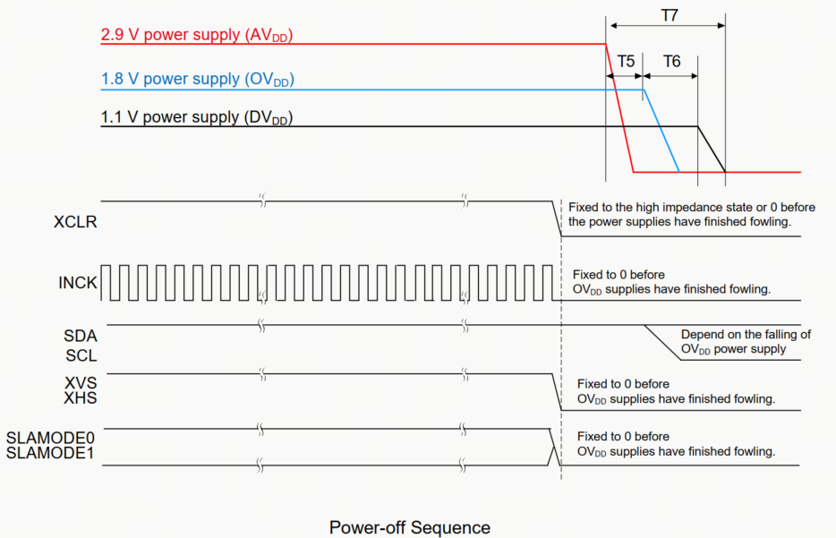
power_off controls sensor power-down through X5 GPIO, following the spec power-on timing sequence.
sensor_poweroff is typically called in sensor_deinit, only XCLR needs to be controlled. The following is the imx415 power_off implementation:
static int sensor_poweroff(sensor_info_t *sensor_info)
{
        int gpio, ret = RET_OK;
        if(sensor_info->gpio_num > 0) {
                for(gpio = 0; gpio < sensor_info->gpio_num; gpio++) {
                        if(sensor_info->gpio_pin[gpio] != -1) {
                                ret = vin_power_ctrl(sensor_info->gpio_pin[gpio],
                                        sensor_info->gpio_level[gpio]);
                                if(ret < 0) {
                                        vin_err("vin_power_ctrl fail\n");
                                        return -HB_CAM_SENSOR_POWEROFF_FAIL;
                                }
                        }
                }
        }
        return ret;
}
init
Write the sensor initialization register list to the sensor via the i2c write function; HDR mode uses the DOL2-specific setting array.
imx415_dol2_data_init is used to populate turning_data information.
sensor_init is called when hbn_camera_attach_to_vin is invoked.
HDR mode uses
sensor_mode == DOL2_Mto take a separate branch.
static int sensor_init(sensor_info_t *sensor_info)
{
        int ret = RET_OK;
        int setting_size = 0;

        ret = sensor_poweron(sensor_info);
        if (ret < 0) {
                vin_err("%d : sensor reset %s fail\n", __LINE__, sensor_info->sensor_name);
                return ret;
        }
        switch(sensor_info->sensor_mode) {
        case NORMAL_M:
                // ... linear mode initialization (omitted) ...
                break;
        case DOL2_M:
                vin_info("imx415 in dol2/hdr mode\n");
                setting_size = sizeof(imx415_init_3840x2160_dol2_4lane_setting) / sizeof(uint32_t) / 2;
                ret = vin_write_array(sensor_info->bus_num, sensor_info->sensor_addr, REG_WIDTH,
                                setting_size, imx415_init_3840x2160_dol2_4lane_setting);
                if (ret < 0) {
                        vin_err("%d : init %s fail\n", __LINE__, sensor_info->sensor_name);
                        return -HB_CAM_I2C_WRITE_FAIL;
                }
                ret = imx415_dol2_data_init(sensor_info);
                if (ret < 0) {
                        vin_err("%d : hdr data init %s fail\n", __LINE__, sensor_info->sensor_name);
                        return -HB_CAM_INIT_FAIL;
                }
                break;
        default:
                vin_err("%d not support mode %d\n", __LINE__, sensor_info->sensor_mode);
                ret = -HB_CAM_INIT_FAIL;
                break;
        }
        return ret;
}
deinit
deinit is typically called for sensor de-initialization, simply call power_off to power down.
sensor_deinit is called when hbn_camera_destroy or hbn_camera_detach_from_vin is invoked.
HDR mode and Linear mode are identical.
static int sensor_deinit(sensor_info_t *sensor_info)
{
        int ret = RET_OK;
        ret = sensor_poweroff(sensor_info);
        if (ret < 0) {
                vin_err("%d : deinit %s fail\n", __LINE__, sensor_info->sensor_name);
                return ret;
        }
        return ret;
}
start
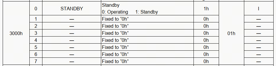
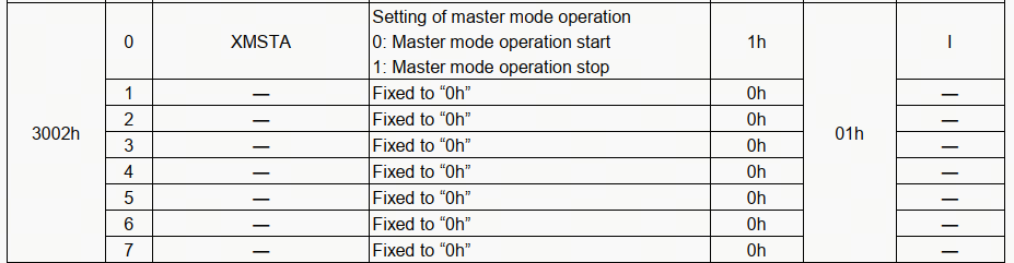
start implements sending stream-on registers 0x3000 as 0x00, 0x3002 as 0x00, to enable sensor streaming.
sensor_start is called when the upper layer calls hbn_vflow_start.
HDR mode and Linear mode use the same stream_on registers.
static int sensor_start(sensor_info_t *sensor_info)
{
        int ret = RET_OK;
        int setting_size = 0;

        switch (sensor_info->sensor_mode) {
        case NORMAL_M:
        case DOL2_M:
                setting_size = sizeof(imx415_stream_on_setting) / sizeof(uint32_t) / 2;
                ret = vin_write_array(sensor_info->bus_num, sensor_info->sensor_addr, 2,
                                      setting_size, imx415_stream_on_setting);
                if (ret < 0) {
                        vin_err("start %s fail\n", sensor_info->sensor_name);
                        return ret;
                }
                break;
        }
        return ret;
}
stop
stop implements sending stream-off registers 0x3000 as 0x01, 0x3002 as 0x01, to disable sensor streaming.
sensor_stop is called when the upper layer calls hbn_vflow_stop.
HDR mode and Linear mode use the same stream_off registers.
static int sensor_stop(sensor_info_t *sensor_info)
{
        int ret = RET_OK;
        int setting_size = 0;

        setting_size = sizeof(imx415_stream_off_setting) / sizeof(uint32_t) / 2;
        vin_info("%s sensor stop\n", sensor_info->sensor_name);
        ret = vin_write_array(sensor_info->bus_num, sensor_info->sensor_addr, REG_WIDTH,
                        setting_size, imx415_stream_off_setting);
        if (ret < 0) {
                vin_err("start %s fail\n", sensor_info->sensor_name);
                return -HB_CAM_I2C_WRITE_FAIL;
        }
        return ret;
}
ISP Configuration and dol2_data_init
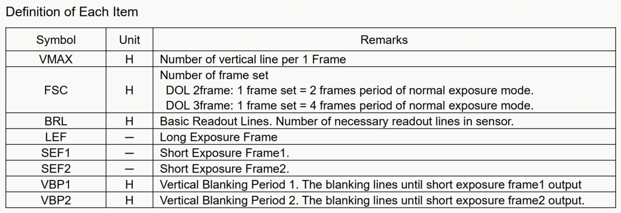
Below are some HDR terminology definitions for imx415:
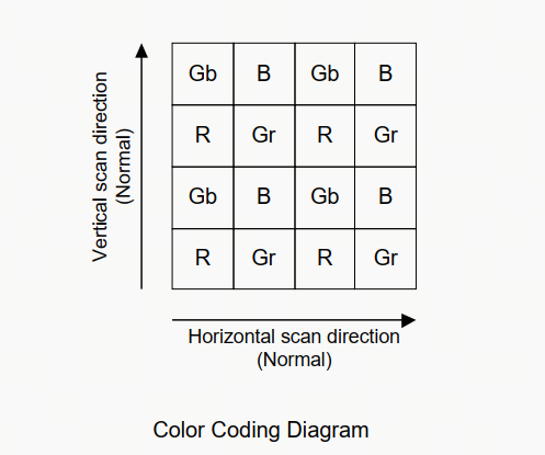
Below is the description of bayer_pattern and bayer_start:
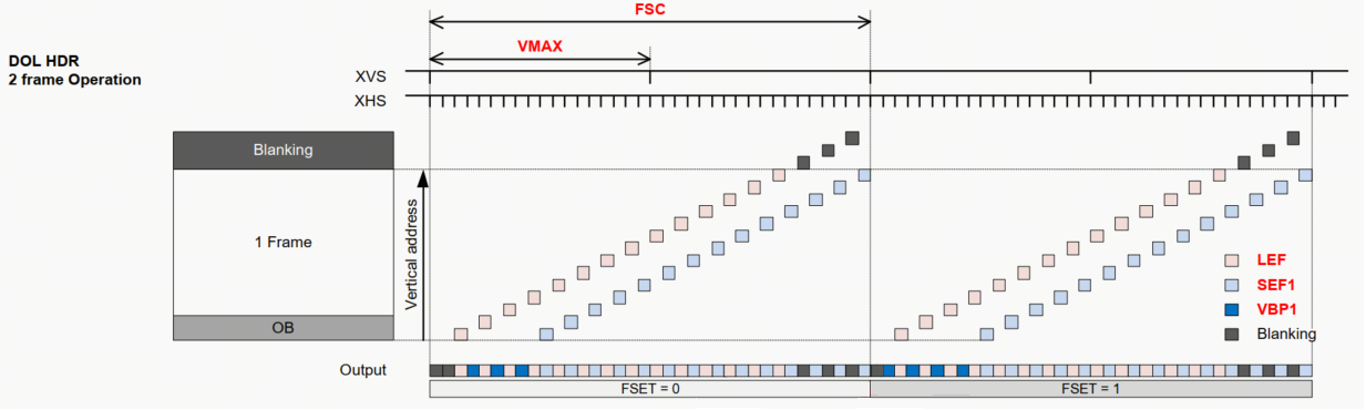
In DOL2 mode, IMX415 needs to alternately output LEF (Long Exposure Frame) and SEF1 (Short Exposure Frame) data within one frame set period. The time occupied is VMAX x 2.
In imx415_dol2_data_init, populate the tuning parameters:
Need to read VMAX (0x3024-0x3026) and RHS1 (0x3060-0x3062) from the sensor, calculate FSC = VMAX x 2;
exposure_time_long_max / exposure_time_max are calculated according to the DOL2 formula in the SPEC;
gain_lut uses
turning_data.dol2.again_lutSet
turning_type = 6.
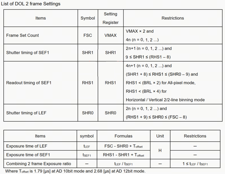
DOL2 exposure time formula from the figure above:
After consulting the sensor FAE, Toffset can be negligible, therefore:
LEF exposure lines:  t_LEF  = FSC  - SHR0,  FSC = VMAX x 2
SEF1 exposure lines: t_SEF1 = RHS1 - SHR1
Key parameter configuration:
lines_per_second = FSC * sensor_info->fps(FSC = VMAX x 2)exposure_time_long_max = FSC - (RHS1 + 9)LEF maximum exposure linesexposure_time_max = RHS1 - 9SEF1 maximum exposure linesexposure_time_min = 8analog_gain_max = 255consistent with the maximum gain_lut indexdigital_gain_max = 0sensor_data_bayer_fill(..., 10, BAYER_START_GB, BAYER_PATTERN_RGGB);sensor_data_bits_fill(..., 12)
static int imx415_dol2_data_init(sensor_info_t *sensor_info)
{
        int ret = RET_OK;
        sensor_turning_data_t turning_data;
        uint32_t *stream_on = turning_data.stream_ctrl.stream_on;
        uint32_t *stream_off = turning_data.stream_ctrl.stream_off;

        int val_l = 0, val_m = 0, val_h = 0;
        uint32_t Vmax = 0, rhs1 = 0, fsc = 0;

        val_l = hb_vin_i2c_read_reg16_data8(sensor_info->bus_num, sensor_info->sensor_addr, IMX415_VMAX);
        val_m = hb_vin_i2c_read_reg16_data8(sensor_info->bus_num, sensor_info->sensor_addr, IMX415_VMAX + 1);
        val_h = hb_vin_i2c_read_reg16_data8(sensor_info->bus_num, sensor_info->sensor_addr, IMX415_VMAX + 2);
        Vmax = ((val_h & 0x0F) << 16) | (val_m << 8) | val_l;

        val_l = hb_vin_i2c_read_reg16_data8(sensor_info->bus_num, sensor_info->sensor_addr, IMX415_RHS1);
        val_m = hb_vin_i2c_read_reg16_data8(sensor_info->bus_num, sensor_info->sensor_addr, IMX415_RHS1 + 1);
        val_h = hb_vin_i2c_read_reg16_data8(sensor_info->bus_num, sensor_info->sensor_addr, IMX415_RHS1 + 2);
        rhs1 = ((val_h & 0x0F) << 16) | (val_m << 8) | val_l;

        fsc = Vmax * 2;

        memset(&turning_data, 0, sizeof(sensor_turning_data_t));

        turning_data.bus_num = sensor_info->bus_num;
        turning_data.bus_type = sensor_info->bus_type;
        turning_data.port = sensor_info->port;
        turning_data.reg_width = sensor_info->reg_width;
        turning_data.mode = sensor_info->sensor_mode;
        turning_data.sensor_addr = sensor_info->sensor_addr;
        strncpy(turning_data.sensor_name, sensor_info->sensor_name,
                sizeof(turning_data.sensor_name));
        turning_data.sensor_data.turning_type = 6;
        turning_data.sensor_data.active_width = sensor_info->width;
        turning_data.sensor_data.active_height = sensor_info->height;

        turning_data.sensor_data.lines_per_second = fsc * sensor_info->fps;
        turning_data.sensor_data.exposure_time_long_max = fsc - (rhs1 + 9);
        turning_data.sensor_data.exposure_time_max = rhs1 - 9;
        turning_data.sensor_data.exposure_time_min = 8;
        turning_data.sensor_data.analog_gain_max = 255;
        turning_data.sensor_data.digital_gain_max = 0;

        sensor_data_bayer_fill(&turning_data.sensor_data, 10, (uint32_t)BAYER_START_GB, (uint32_t)BAYER_PATTERN_RGGB);
        sensor_data_bits_fill(&turning_data.sensor_data, 12);

        turning_data.stream_ctrl.data_length = 1;
        memcpy(stream_on, imx415_stream_on_setting, sizeof(imx415_stream_on_setting));
        memcpy(stream_off, imx415_stream_off_setting, sizeof(imx415_stream_off_setting));

        turning_data.dol2.again_lut = malloc(256 * sizeof(uint32_t));
        if (turning_data.dol2.again_lut != NULL) {
                memset(turning_data.dol2.again_lut, 0xff, 256 * sizeof(uint32_t));
                memcpy(turning_data.dol2.again_lut, imx415_gain_lut, sizeof(imx415_gain_lut));
        }

        ret = ioctl(sensor_info->sen_devfd, SENSOR_TURNING_PARAM, &turning_data);

        if (turning_data.dol2.again_lut) {
                free(turning_data.dol2.again_lut);
                turning_data.dol2.again_lut = NULL;
        }
        if (ret < 0) {
                vin_err("%s sync gain lut ioctl fail %d\n", sensor_info->sensor_name, ret);
                return -RET_ERROR;
        }
        return ret;
}
aexp_gain_control
In DOL2 mode, LEF and SEF1 gain need to be controlled separately:
again[0]-> LEF gain, written to GAIN_PGC0 (0x3090)again[1]-> SEF1 gain, written to GAIN_PGC1 (0x3092)
static int sensor_aexp_gain_control(hal_control_info_t *info, uint32_t mode, uint32_t *again, uint32_t *dgain, uint32_t gain_num)
{
        const uint16_t AGAIN = GAIN_PGC0;
        const uint16_t S_AGAIN = GAIN_PGC1;
        char again_reg_value = 0, s_again_reg_value = 0;
        int again_index = 0, s_again_index = 0;

        if (mode == NORMAL_M) {
                if (again[0] >= sizeof(imx415_gain_lut)/sizeof(uint32_t))
                        again_index = sizeof(imx415_gain_lut)/sizeof(uint32_t) - 1;
                else
                        again_index = again[0];

                again_reg_value = (imx415_gain_lut[again_index] >> 0) & 0xFF;
                set_gain_registers(info, AGAIN, again_reg_value);
        } else if (mode == DOL2_M) {
                if (again[0] >= sizeof(imx415_gain_lut)/sizeof(uint32_t))
                        again_index = sizeof(imx415_gain_lut)/sizeof(uint32_t) - 1;
                else
                        again_index = again[0];
                if (again[1] >= sizeof(imx415_gain_lut)/sizeof(uint32_t))
                        s_again_index = sizeof(imx415_gain_lut)/sizeof(uint32_t) - 1;
                else
                        s_again_index = again[1];

                again_reg_value = (imx415_gain_lut[again_index] >> 0) & 0xFF;
                s_again_reg_value = (imx415_gain_lut[s_again_index] >> 0) & 0xFF;

                set_gain_registers(info, AGAIN, again_reg_value);
                set_gain_registers(info, S_AGAIN, s_again_reg_value);
        } else {
                vin_err(" unsupport mode %d\n", mode);
        }
        return 0;
}
aexp_line_control
aexp_line_control in DOL2 mode needs to set both LEF and SEF1 exposure simultaneously, mainly responsible for:
Receiving exposure line counts from the ISP 3A algorithm:
line[0](LEF),line[1](SEF1)Converting exposure line counts to SHR0 and SHR1 register values
Performing boundary checks and odd/even alignment
Sending to sensor via i2c
DOL2 Exposure Formula:
SHR0 = FSC  - line[0]     (LEF,  FSC = VMAX x 2)
SHR1 = RHS1 - line[1]     (SEF1)

Constraints: SHR0 is even (2n),    (RHS1 + 9) <= SHR0 <= (FSC - 8)
             SHR1 is odd (2n+1),   9 <= SHR1 <= (RHS1 - 8)
Linear Mode Exposure Formula:
SHR0 = VMAX - line[0]

Constraints: 8 <= SHR0 <= (VMAX - 4)
static int sensor_aexp_line_control(hal_control_info_t *info, uint32_t mode, uint32_t *line, uint32_t line_num)
{
        uint32_t tmp = 0;
        char temp0 = 0, temp1 = 0, temp2 = 0;
        int val_l = 0, val_m = 0, val_h = 0;
        uint32_t Vmax = 0;

        val_l = hb_vin_i2c_read_reg16_data8(info->bus_num, info->sensor_addr, IMX415_VMAX);
        val_m = hb_vin_i2c_read_reg16_data8(info->bus_num, info->sensor_addr, IMX415_VMAX + 1);
        val_h = hb_vin_i2c_read_reg16_data8(info->bus_num, info->sensor_addr, IMX415_VMAX + 2);
        Vmax = ((val_h & 0x0F) << 16) | (val_m << 8) | val_l;

        if ((mode == NORMAL_M) || (line_num == 1)) {
                int shr0 = Vmax - line[0];
                if (shr0 < 8)              shr0 = 8;
                if (shr0 > (int)(Vmax - 4)) shr0 = Vmax - 4;

                tmp = shr0;
                temp2 = (tmp >> 16) & 0x0F;
                vin_i2c_write8(info->bus_num, 16, info->sensor_addr, IMX415_SHR0 + 2, temp2);
                temp1 = (tmp >> 8) & 0xFF;
                vin_i2c_write8(info->bus_num, 16, info->sensor_addr, IMX415_SHR0 + 1, temp1);
                temp0 = (tmp & 0xFF);
                vin_i2c_write8(info->bus_num, 16, info->sensor_addr, IMX415_SHR0, temp0);
        } else if (mode == DOL2_M) {
                uint32_t rhs1 = 0, fsc = 0;
                int shr0 = 0, shr1 = 0;

                val_l = hb_vin_i2c_read_reg16_data8(info->bus_num, info->sensor_addr, IMX415_RHS1);
                val_m = hb_vin_i2c_read_reg16_data8(info->bus_num, info->sensor_addr, IMX415_RHS1 + 1);
                val_h = hb_vin_i2c_read_reg16_data8(info->bus_num, info->sensor_addr, IMX415_RHS1 + 2);
                rhs1 = ((val_h & 0x0F) << 16) | (val_m << 8) | val_l;

                fsc = Vmax * 2;
                shr0 = fsc - line[0];
                shr1 = rhs1 - line[1];

                if (shr1 < 9)              shr1 = 9;
                if (shr1 > (int)(rhs1 - 8)) shr1 = rhs1 - 8;
                if (shr0 < (int)(rhs1 + 9)) shr0 = rhs1 + 9;
                if (shr0 > (int)(fsc - 8))   shr0 = fsc - 8;

                shr1 |= 0x01;               // Force SHR1 to odd (2n+1)
                shr0 = (shr0 >> 1) << 1;    // Force SHR0 to even (2n)

                // Write SHR0 (3 bytes LSB first: 0x3050, 0x3051, 0x3052)
                tmp = shr0;
                vin_i2c_write8(info->bus_num, 16, info->sensor_addr, IMX415_SHR0 + 2, (tmp >> 16) & 0x0F);
                vin_i2c_write8(info->bus_num, 16, info->sensor_addr, IMX415_SHR0 + 1, (tmp >> 8) & 0xFF);
                vin_i2c_write8(info->bus_num, 16, info->sensor_addr, IMX415_SHR0,     tmp & 0xFF);

                // Write SHR1 (3 bytes LSB first: 0x3054, 0x3055, 0x3056)
                tmp = shr1;
                vin_i2c_write8(info->bus_num, 16, info->sensor_addr, IMX415_SHR1 + 2, (tmp >> 16) & 0x0F);
                vin_i2c_write8(info->bus_num, 16, info->sensor_addr, IMX415_SHR1 + 1, (tmp >> 8) & 0xFF);
                vin_i2c_write8(info->bus_num, 16, info->sensor_addr, IMX415_SHR1,     tmp & 0xFF);
        } else {
                vin_err(" unsupport mode %d\n", mode);
                return -1;
        }
        return 0;
}
userspace_control
sensor_userspace_control is used here for Gain Control and Exposure Control switches.
Used during hbplayer debugging to troubleshoot flicker or abnormal images; HAL_GAIN_CONTROL / HAL_LINE_CONTROL can be toggled to isolate the issue.
HDR mode and Linear mode are identical.
static int sensor_userspace_control(uint32_t port, uint32_t *enable)
{
        vin_info("enable userspace gain control and line control\n");
        *enable = HAL_GAIN_CONTROL | HAL_LINE_CONTROL;
        return 0;
}
Driver Deployment
Build with
./bd.sh hbre camsys/libcam.Copy
out/deploy/hbre/lib/sensor/libimx415.so.1.0.0to/usr/hobot/lib/sensor/on the board.
5.17.6.3. App Configuration
Add DOL2 configuration for imx415 in the path
app/samples/platform_samples/vp_sensors/imx415/.HTS/VTS can be read from registers 0x3028/0x3029, 0x3024~0x3026, or obtained by consulting the Sensor FAE, or measured with an oscilloscope. For measurement methods, refer to MIPI Parameter Determination
mipiclk can generally be obtained from the Sensor FAE. For calculation methods, refer to MIPI CLK
Other parameters are common configurations. Refer to Data Structures for configuration.
vp_sensor Configuration File: dol2_3840x2160_raw10_30fps_4lane.c
Configuration file path:
imx415/dol2_3840x2160_raw10_30fps_4lane.c.Configuration struct name:
imx415_dol2_3480x2160_raw10_30fps_4lane(must be registered in vp_sensor_config_list).The current example uses RAW10 output; datatype/format is configured as 0x2B.
DOL2 mode has several key differences from Linear mode, described module by module below:
MIPI Configuration
In DOL2 mode, the sensor transmits LEF (VC0) and SEF1 (VC1) over the same MIPI link using Virtual Channels. The SoC side needs to configure 2 channels to receive them separately:
static mipi_config_t imx415_mipi_config = {
        .rx_enable = 1,
        .rx_attr = {
                .phy = 0,
                .lane = 4,
                .datatype = RAW10,
                .fps = 30,
                .mclk = 1,
                .mipiclk = 7128,
                .width = 3840,
                .height = 2160,
                .linelenth = 6400,
                .framelenth = 4700,
                .settle = 10,
                .channel_num = 2,          // DOL2: 2 channels (Linear is 1)
                .channel_sel = {0, 1},     // VC0=LEF, VC1=SEF1
        },
        .rx_ex_mask = 0x40,
        .rx_attr_ex = {
                .stop_check_instart = 1,
        }
};
Differences from Linear mode:
channel_num = 2: DOL2 requires receiving data from two virtual channels VC0 and VC1, Linear is 1channel_sel = {0, 1}: Specifies receiving VC0 and VC1framelenth: DOL2 and Linear frame lengths differ, verify based on actual VMAX configuration
Camera Configuration
static camera_config_t imx415_camera_config = {
        .name = "imx415",
        .addr = 0x1a,
        .sensor_mode = DOL2_M,                    // DOL2 mode (Linear is NORMAL_M)
        .fps = 30,
        .format = RAW10,
        .width = 3840,
        .height = 2160,
        .gpio_enable_bit = 0x01,
        .gpio_level_bit = 0x00,
        .mipi_cfg = &imx415_mipi_config,
        .calib_lname = "imx415_hdr_tuning.json",  //HDR-specific tuning file
};
Differences from Linear mode:
sensor_mode = DOL2_M: Determines that driver init/start/gain/line take the DOL2 branchcalib_lname: Requires an HDR-specific tuning file
VIN Configuration
VIN configuration is the part with the most differences between DOL2 and Linear:
static vin_node_attr_t imx415_vin_node_attr = {
        .cim_attr = {
                .mipi_rx = 0,
                .vc_index = 0,             // Start from VC0
                .ipi_channel = 2,          // DOL2: 2 IPI channels (Linear is 1)
                .cim_isp_flyby = 1,        // DOL2 only supports online mode
                .func = {
                        .enable_frame_id = 1,
                        .set_init_frame_id = 0,
                        .hdr_mode = DOL_2,  //Notify ISP to do two-frame synthesis (Linear is NOT_HDR)
                        .time_stamp_en = 0,
                },
        },
};
Key parameter description (refer to VIN API Data Structures):
| Parameter | Linear Value | DOL2 Value | Description |
|---|---|---|---|
ipi_channel |
1 | 2 | DOL2 requires 2 IPI channels to receive VC0 (LEF) and VC1 (SEF1) separately |
cim_isp_flyby |
0 | 1 | DOL2 typically uses VIN online ISP (PASSTHROUGH_MODE) |
hdr_mode |
NOT_HDR (0) | DOL_2 (1) | 0: no multi-frame synthesis; 1: SoC does two-frame synthesis; 2: three-frame synthesis (not supported by X5) |
VIN output channel configuration:
static vin_ochn_attr_t imx415_vin_ochn_attr = {
        .ddr_en = 0,                   // 0 in online mode
        .ochn_attr_type = VIN_BASIC_ATTR,
        .vin_basic_attr = {
                .format = RAW10,
                .wstride = (SENSOR_WIDTH) * 2,
        },
};
ISP Configuration
ISP needs to be set to DOL2 synthesis mode, working with VIN online:
static isp_attr_t imx415_isp_attr = {
        .input_mode = PASSTHROUGH_MODE,  // online
        .sensor_mode = ISP_DOL2_M,       // DOL2 synthesis mode
        .tile_mode = 0,
        .crop = {
                .x = 0, .y = 0,
                .h = 2160, .w = 3840,
        },
};
Key parameter description (refer to HBN API Data Structures):
| Parameter | Linear Value | DOL2 Value | Description |
|---|---|---|---|
input_mode |
DDR_MODE (2) | PASSTHROUGH_MODE (0) | Corresponds to cim_isp_flyby=1, VIN and ISP connect without going through DDR |
sensor_mode |
ISP_NORMAL_M (0) | ISP_DOL2_M (1) | ISP performs DOL2 two-frame HDR synthesis internally |
Note: When using VIN online ISP, the binding method for
hbn_vflow_bind_vnodeissrc_out_channel=1, dst_input_channel=0, which differs from thesrc_out_channel=0used in Linear offline mode.
Complete Parameter Summary
| Configuration Item | Parameter Name / Location | Value Description |
|---|---|---|
| Top-level | config_file |
"dol2_3840x2160_raw10_30fps_4lane.c" |
sensor_name |
"imx415-30fps-4lane-dol2" |
|
chip_id_reg / chip_id |
0x3F12 / 0x0514 | |
sensor_i2c_addr_list |
{0x1A} | |
support_sensor_mode |
{DOL2_M} | |
| MIPI | lane |
4 |
datatype |
RAW10 (0x2B) | |
fps |
30 | |
mipiclk |
7128 (Mbps) | |
width / height |
3840 / 2160 | |
linelenth / framelenth |
6400 / 4700 | |
settle |
10 | |
channel_num |
2 | |
channel_sel |
{0, 1} | |
stop_check_instart |
1 | |
| Camera | name / addr |
"imx415" / 0x1A |
sensor_mode |
DOL2_M | |
format |
RAW10 | |
gpio_enable_bit / gpio_level_bit |
0x01 / 0x00 | |
calib_lname |
"imx415_hdr_tuning.json" |
|
| VIN | mipi_rx |
0 |
vc_index |
0 | |
ipi_channel |
2 | |
cim_isp_flyby |
1 (online) | |
hdr_mode |
DOL_2 | |
mclk_freq (vin_attr_ex) |
24000000 | |
| VIN Output | ddr_en |
0 (online mode) |
wstride |
SENSOR_WIDTH x 2 (RAW10 is x2) | |
| ISP Input | input_mode |
PASSTHROUGH_MODE |
sensor_mode |
ISP_DOL2_M | |
crop |
x=0, y=0, w=3840, h=2160 | |
input_fmt |
FRM_FMT_RAW | |
input_bit_width |
10 | |
| ISP Output | output_fmt |
FRM_FMT_NV12 |
output_bit_width |
8 | |
ddr_en |
1 |
5.17.6.4. Program Verification
get_vin_data: Confirm that raw images have no severe color cast and frame rate matches the configuration. In DOL2 mode, there will be data from two channels.
get_isp_data: Prepare
imx415_hdr_tuning.json(can copy an HDR json of the same resolution and change sensor_name), confirm that the ISP-synthesized YUV image is normal, and that bright and dark areas have richer detail compared to Linear mode.hbplayer: Connect to the board to preview short frame, long frame, and YUV data. See hbplayer and tuning_tool Usage Guide.
tuning_tool: Use tuning_tool to connect to hbplayer, enter command
e, configure Manual AE, set aGain and integrationTime for LEF and SEF1 respectively, check driver prints to verify SHR0 (0x3050~0x3052), SHR1 (0x3054~0x3056), GAIN_PGC0 (0x3090), GAIN_PGC1 (0x3092) match the spec. ISP gain limits can be configured in imx415_hdr_tuning.json for self-testing.
For common issues, see Camera Sensor FAQ.