3.13. sample_imu 使用说明
3.13.1. 概述
3.13.1.1. 功能简介
sample_imu 提供sample_imu 子目录
IIO 通路:通过 sysfs 读取 IIO 设备
节点,支持 交互式 单帧/多 帧 采集,并 将 数据 转换 为 SI 单位 输出。 Input 通路:通过 Linux Input 子系统
读取 驱动 上报 的 EV_MSC事件,适合验证 驱动 连续 上报 链路 与 丢 包 情况。
3.13.1.2. sample_imu 架构说明
sample_imu 包含
| 目录 | 描述 |
|---|---|
| sample_imu_iio | 基于 IIO 接口bmi08x、icm42688-gyro、icm42688-accel |
| sample_imu_input | 基于 Linux Input 子系统 |
3.13.2. sample_imu_iio
3.13.2.1. 功能概述
sample_imu_iio 是
程序
bmi08xicm42688-gyroicm42688-accel
未-n 指定get_default_imu_name() 自动
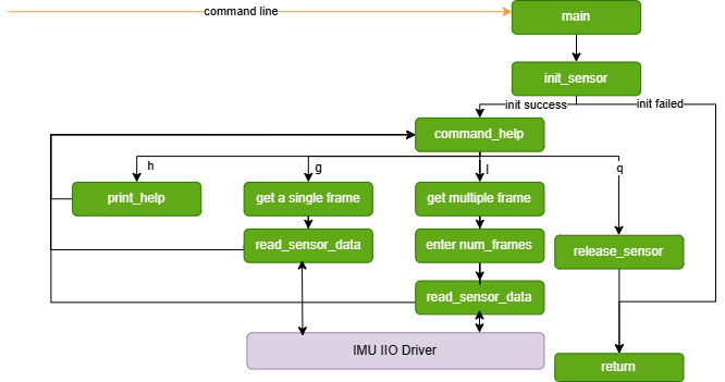
3.13.2.2. 软件架构说明
sample_imu_iio 采用
应用层:
sample_imu.c作为程序 入口,负责 解析 命令行 参数、初始化 传感器、处理 用户 输入 命令,以及 读取 和 显示 传感器 数据。 管理层:
imu_manager.h和imu_manager.c提供传感器 管理 接口,包括 列出 可用 传感器、初始化 传感器、读取数据、释放 资源 等。 适配
层 :imu_interface.h定义传感器 驱动 接口 结构 体,为 具体 传感器 提供 统一 抽象。 传感器
抽象 :层 bmi08x.c、icm42688.c等文件 负责 与 底层 IIO 驱动 交互,将 硬件 数据 转换 为 上层 可用 的 标准 数据格式。
软件架构
3.13.2.3. 数据流说明
应用层
通过 init_sensor()在/sys/bus/iio/devices/下查找 并 校验 目标 IIO 设备。 传感器
抽象 层 从 in_accel_*_raw、in_anglvel_*_raw等节点 读取 原始 值,并 结合 scale 转换 为 物理量。 应用层
通过 read_sensor_data()获取一帧 ImuData,再调用 print_imu_data()输出加速度(m/s²)、角速度(rad/s)和 时间 戳。
3.13.2.4. 代码位置及目录结构
代码
位置: app/samples/platform_samples/sample_imu/sample_imu_iio目录
结构
sample_imu_iio
├── Makefile
├── bmi08x.c
├── icm42688.c
├── imu_interface.h
├── imu_manager.c
├── imu_manager.h
└── sample_imu.c
各
Makefile:定义
编译 规则,编译 产物 为 sample_imu_iio。sample_imu.c:程序
入口,负责 命令行 解析 与 交互式 读数。 imu_manager.c / imu_manager.h:传感器
管理 与 IIO 设备 探测 逻辑。 imu_interface.h:传感器
驱动 统一 接口定义。 bmi08x.c:BMI08x 传感器
抽象 层 实现。 icm42688.c:ICM42688 加速度计/陀螺仪
抽象 层 实现。
如需bmi08x.c 的imu_interface.h 接口
3.13.2.5. 背景知识
惯性
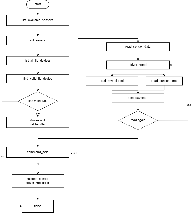
3.13.2.6. API 流程说明
sample_imu_iio 主要
列出
可用 :调用传感器 list_available_sensors(),遍历程序 内置 支持 的 传感器 驱动 列表 并打印 名称。 初始化
传感器 :调用init_sensor(),传入传感器 类型 后 查找 并 校验 对应 IIO 设备,再 调用 具体 驱动 初始化 函数。 读取
传感器 :调用数据 read_sensor_data(),由传感器 抽象 层 读取 一帧 数据 并 填充 到 ImuData。释放
传感器 :调用资源 release_sensor(),释放驱动 上下文 与 句柄。
3.13.2.7. 编译部署
编译
进入
sample_imu_iio目录,执行make编译输出
成果 物是 该 源码 目录 下 的 sample_imu_iio详细
程序 编译 方式 请 查阅 编译 方法 章节
硬件环境搭建
可以
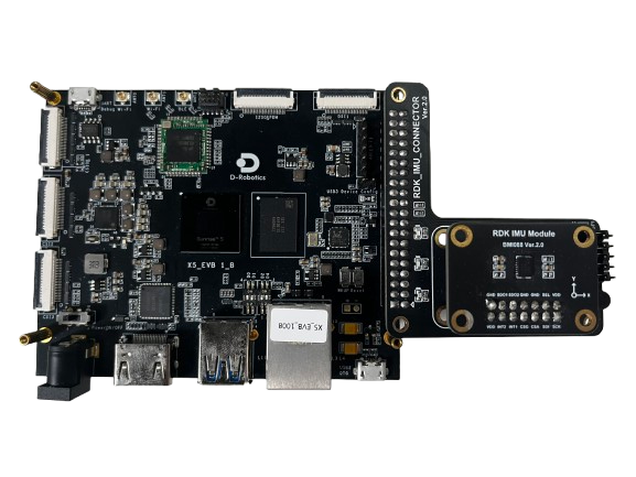
确认
首先x5-evb.dtsi 文件,检查i2c5 节点
&i2c5 {
	status = "okay";
    ......
	bmi08a@19 {
		compatible = "bmi08xa";
		reg = <0x19>;
		interrupt-parent = <&ls_gpio1_porta>;
		interrupts = <4 IRQ_TYPE_EDGE_RISING>;
		status = "okay";
	};

	bmi08g@69 {
		compatible = "bmi08xg";
		reg = <0x69>;
		interrupt-parent = <&ls_gpio1_porta>;
		interrupts = <6 IRQ_TYPE_EDGE_RISING>;
		status = "okay";
	};
};
该 IMU 也
&spi1 {
	/*When dual chip select is used, the number of SPI chip selects must be set to 2.*/
	/*num-cs = <2>;*/
	status = "okay";
	pinctrl-names = "default";
	pinctrl-0 = <&pinctrl_spi1 &pinctrl_spi1_ssn1>;
	dma-names = "tx", "rx";
	dmas = <&axi_dmac 23>, <&axi_dmac 22>;

	bmi08g@0 {
		compatible = "bmi088_gyro";
		reg = <0>;
		spi-max-frequency = <5000000>;
		interrupt-parent = <&dsp_gpio_porta>;
		interrupts = <12 IRQ_TYPE_EDGE_RISING>;
		gyro-irq-gpio = <&dsp_gpio_porta 12 GPIO_ACTIVE_HIGH>;
		status = "okay";
	};

	bmi08a@1 {
		compatible = "bmi08a";
		reg = <1>;
		spi-max-frequency = <5000000>;
		interrupt-parent = <&ls_gpio0_porta>;
		interrupts = <2 IRQ_TYPE_EDGE_RISING>;
		accel-irq-gpio = <&ls_gpio0_porta 2 GPIO_ACTIVE_HIGH>;
		status = "okay";
	};
};
注意:I2C 与 SPI 只能disabled。
然后hobot_x5_soc_defconfig)是否
CONFIG_BMI08X_SUPPORT_I2C_BUS=m
CONFIG_BMI08X_SUPPORT_SPI_BUS=m
可以
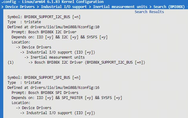
打开方式
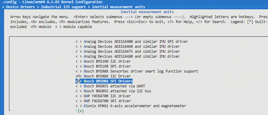
最后
(1)通过 LOG 检查
root@buildroot:~# dmesg | grep BS
[    0.084965] CPU features: detected: Speculative Store Bypassing Safe (SSBS)
               [I]\x016<BS_LOG><bmi08_i2c_probe><187>client->name:bmi08xa / addr: 0x19
               [I]\x016<BS_LOG><bmi08_i2c_probe><187>client->name:bmi08xg / addr: 0x69
               [I]\x016<BS_LOG><sensor_init><1057>accel initilized
               [I]\x016<BS_LOG><sensor_init><1064>gyro initilized
               [I]\x016<BS_LOG><sensor_init><1065>sensor initilized
               [I]\x016<BS_LOG><sensor_init><1072>soft reset done
               [I]\x016<BS_LOG><sensor_init><1080>config stream loaded successfully
               [I]\x016<BS_LOG><sensor_init><1090>Accel power mode set to NORMAL
               [I]\x016<BS_LOG><sensor_init><1099>Gyro power mode set to NORMAL
               [I]\x016<BS_LOG><bmi08_probe><2216>Acc chip ID : 0x1e, Gyro chip ID : 0xf
               [I]\x016<BS_LOG><bmi08_request_irq><544>ACC IRQ requested for pin : 56
               [I]\x016<BS_LOG><bmi08_probe><2227>ACC IRQ requested
               [I]\x016<BS_LOG><bmi08_gyr_request_irq><563>GYR IRQ requested for pin : 57
               [I]\x016<BS_LOG><bmi08_probe><2234>GYR IRQ requested
               [I]\x016<BS_LOG><bmi08_probe><2236>sensor bmi088 probed successfully
[    4.687140] CAM_SUBSYS soc:cam:cam_sys@0: [FRT:D] camsys_probe(0)
root@buildroot:~#
可以
[I]\x016<BS_LOG><bmi08_probe><2216>Acc chip ID : 0x1e, Gyro chip ID : 0xf
(2)通过 IIO 子系统name 节点
root@buildroot:~# cd /sys/bus/iio/devices/iio\:device1/
root@buildroot:/sys/bus/iio/devices/iio:device1# cat name
bmi08x
root@buildroot:/sys/bus/iio/devices/iio:device1#
程序部署
把 sample_imu_iio 上chmod +x sample_imu_iio 赋予
板端
/app/platform_samples/sample_imu/sample_imu_iio/sample_imu_iio
3.13.2.8. 运行
程序运行方法
直接
./sample_imu_iio -h
不带
./sample_imu_iio
也-n 显式
./sample_imu_iio -n bmi08x
./sample_imu_iio -n icm42688-gyro
程序参数选项说明
Usage: sample_imu_iio [OPTIONS]
Options:
  -n <imu_name>         Specify IMU name (default: auto-detected)
  -h                    Show this help message
Supported sensors: bmi08x icm42688-gyro icm42688-accel
参数
-n <imu_name>:指定 IMU 传感器名称。未指定 时,程序 自动 探测 第一个 可用 设备。 -h:显示帮助 信息,并列 出 程序 内置 支持 的 传感器 名称。
运行效果
程序运行
root@buildroot:/app/platform_samples/sample_imu/sample_imu_iio# ./sample_imu_iio
No IMU specified, using detected default: bmi08x
Using IMU: bmi08x

=== Detected IIO Devices ===
  Device: iio:device1     | Name: bmi08x
  Device: iio:device0     | Name: 34190000.adc
============================

Device validation passed at: /sys/bus/iio/devices/iio:device1
BMI08x: Initializing with params:

***************  Command Lists  ***************
 g    -- Get a single frame of imu data
 l    -- Get multiple frames of imu data
 q    -- Quit the program
 h    -- Print this help message
Enter command:
命令
g:获取一帧 IMU 数据 l:获取多 帧 IMU 数据,需 输入 帧 数 q:退出程序 h:显示帮助 信息
获取
Enter command: g
Data received (Frame 1):
  Accelerometer: [-117.836021, -118.283142, 9.569026] m/s²
  Gyroscope:     [0.006392, -69.885605, 0.049002] rad/s
  Timestamp:     00:01:38.917.929
获取
Enter command: l
Enter number of frames to read: 3
Data received (Frame 1):
  Accelerometer: [-117.870140, -118.261597, 9.597756] m/s²
  Gyroscope:     [0.019175, 0.010653, -69.857903] rad/s
  Timestamp:     00:01:50.861.640
Data received (Frame 2):
  Accelerometer: [-117.825249, -118.283142, 9.574412] m/s²
  Gyroscope:     [0.014914, -69.857903, -69.887733] rad/s
  Timestamp:     00:01:50.867.500
......
3.13.2.9. 常见问题
已经
首先
确认 硬件 连接 是否 正确,检查 IMU 与 开发板 之间 的 连线 是否 松动、短路 或 接错。可 参考 开发板 使用指南 中 的 40PIN 连接 说明。 其次
检查 驱动 是否 已 向 IIO 框架 正常 注册。 sample_imu_iio运行时会 列举 IIO 下 所有 设备;若 未 发现 期望 设备,请 检查 驱动 注册 情况,具体 可 参考 上文 硬件 环境 。搭建 若需
支持 新 的 IMU 型号,请 先 在 IIO 框架 下 完成 驱动 注册,再 参考 bmi08x.c在sample_imu_iio中扩展 传感器 抽象 层。
3.13.3. sample_imu_input
3.13.3.1. 功能概述
sample_imu_input 演示sample_imu_iio 的 sysfs 轮询/读取/dev/input/eventX 节点,解析EV_MSC 事件
本
持续
读取 驱动 上报 事件,无 交互式 g/l/q菜单输出
六轴 原始 LSB 值 与 64 位 硬件 时间 戳(ns) 当
相邻 帧 时间 戳 间隔 超过 3.5 ms 时,判定 为 可能 丢包 并打印 告警
硬件
3.13.3.2. 软件架构说明
sample_imu_input.c 从 main 入口
每次
并
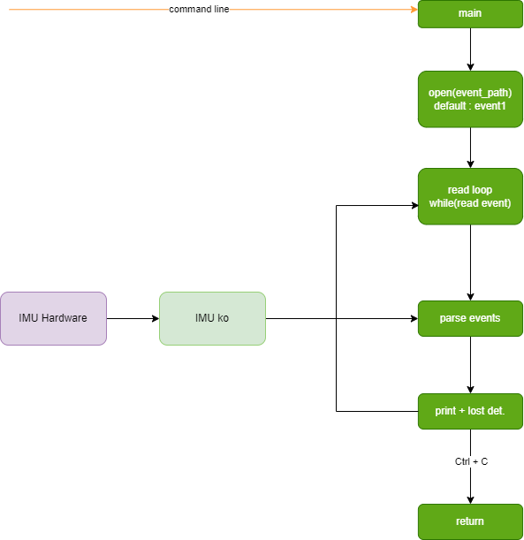
3.13.3.3. 数据流说明
内核 BMI088 驱动
在 每次 采样 完成 后,通过 Input 子系统 上报 若干 EV_MSC事件(code = BMI088_MSC_DATA)。一帧
数据 以 SYN_REPORT结束;应用层在 收到 SYN_REPORT时,将缓存 的 9 个 MSC 字 段 组装 为 一帧 IMU 数据。 应用层
打印 ACC/GYRO 原始 值、时间 戳 和 IRQ 计数,并 根据 相邻 时间 戳 差值 统计 丢包 情况。
每帧 MSC 字
| 索引 | 含义 |
|---|---|
| 0 ~ 2 | 加速度计 X/Y/Z 原始 |
| 3 ~ 5 | 陀螺仪 X/Y/Z 原始 |
| 6 ~ 7 | 硬件 |
| 8 | IRQ 计数 |
3.13.3.4. 代码位置及目录结构
代码
位置: app/samples/platform_samples/sample_imu/sample_imu_input目录
结构
sample_imu_input
├── Makefile
├── sample_imu_input.c
└── sample_imu_input
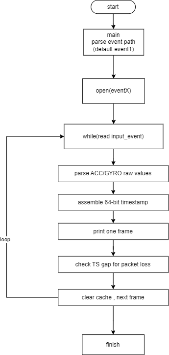
3.13.3.5. API 流程说明
sample_imu_input 基于
open()打开/dev/input/eventX设备节点。 循环
read()读取input_event结构体。 对
EV_MSC事件缓存 字 段,对 SYN_REPORT事件完成 组帧 与 打印。 根据
相邻 帧 硬件 时间 戳 差值 判断 是否 丢包。 程序
退出 时 close()设备并 输出 统计 信息。
3.13.3.6. 编译部署
编译
进入
sample_imu_input目录,执行make编译输出
成果 物是 该 源码 目录 下 的 sample_imu_input详细
程序 编译 方式 请 查阅 编译 方法 章节
程序部署
把 sample_imu_input 上chmod +x sample_imu_input 赋予
板端
/app/platform_samples/sample_imu/sample_imu_input/sample_imu_input
驱动
cat /proc/bus/input/devices
ls -l /dev/input/event*
请event 节点;程序/dev/input/event1。
3.13.3.7. 运行
程序运行方法
使用
./sample_imu_input
指定 Input 设备
./sample_imu_input /dev/input/event2
程序Ctrl+C 退出。
程序参数选项说明
本getopt 风格
./sample_imu_input [input_device_path]
input_device_path(可选):Input 设备 节点 路径,默认 /dev/input/event1。
运行效果
========================================
BMI088 input reader (unified MSC code)
Device path: /dev/input/event1
Press Ctrl+C to exit
========================================

ACC(-117,-118,9) | GYRO(0,-69,0) | TS:9876543210 ns | Lost: 0 | EventCount: 9 | up_count: 128 | lower_count: -
ACC(-117,-118,9) | GYRO(0,-69,0) | TS:9879876543 ns | Lost: 0 | EventCount: 9 | up_count: 129 | lower_count: -
[ERROR] IMU data lost: last ts 0.009876s, current ts 0.009883s, diff 0.000007s
......
字
ACC(x,y,z)/GYRO(x,y,z):六轴原始 LSB 值 TS:由驱动 上报 高低 32 位 组装 的 硬件 时间 戳(ns) Lost:累计疑似 丢包 次数 EventCount:当前帧 收到 的 input 事件 数量 up_count:驱动上报 的 IRQ 计数 [ERROR] IMU data lost: 丢包的 标志,丢包 的 时间 间隔 需要 根据 具体 方案 需求,对 程序 做 修改。
3.13.3.8. 常见问题
打开 /dev/input/eventX 失败
请
先 确认 IMU 驱动 是否 已 成功 加载,硬件 连接 与 内核 配置 请 参考 sample_imu_iio 硬件 环境 。搭建 使用
cat /proc/bus/input/devices确认 IMU 对应的 event节点编号,并 在 启动 命令 中 传入 正确 路径。
能
确认
驱动 是否 已 使 能 数据流 上报;部分 场景 需先 完成 IIO/Input 驱动 的 probe 与 中断 配置。 检查
是否 选错 了 event节点(系统中 可能 存在 键盘、触摸板 等 其他 Input 设备)。
如何
程序
默认 以 相邻 帧 硬件 时间 戳 差值 大于 3.5 ms 作为 丢包 判定 阈值;出现 丢包 时会 打印 [ERROR] IMU data lost日志。