4.5.9. Ethernet Performance Testing
This chapter aims to guide how to use the iperf3 tool for Ethernet performance testing. Refer to iperf3 for detailed usage instructions of this command.
Key aspects of Ethernet performance testing:
Bandwidth and Throughput: Test the actual available bandwidth of the Ethernet connection to determine its performance under high load conditions.
Latency: Evaluate the transmission delay of data over Ethernet, especially under high load. Increased latency may negatively impact real-time applications.
Packet Loss Rate: Measure the rate of packet loss in the Ethernet network to assess its stability. Excessive packet loss affects the integrity of data transmission.
MTU (Maximum Transmission Unit): Verify NIC MTU configuration and whether the end-to-end path can correctly send and receive full-size packets at different MTU tiers.
4.5.9.1. Throughput Testing
Test Principle
Ethernet performance testing relies on data transmission between a client and a server. The specific principles are as follows:
Server Side: Use
iperf3to listen on a specified port and wait for client connections. The server calculates actual bandwidth and throughput by recording the amount of received data and time intervals.Client Side: The client actively connects to the server and sends data packets at a specified rate and interval, simulating network traffic load.
Statistics: During the test,
iperf3records key metrics such as bandwidth, latency, packet loss rate, and retransmission counts, aiding in network performance analysis.
Preparations
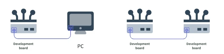
Choose Connection Method: Direct connection between
development board-computer, ordevelopment board-development board.Determine Server and Client: The development board can act as either client or server; the peer device can be a personal computer (PC) or another development board.
Define Network Segment: Configure IP addresses within the same subnet.
Example Configuration
The following configuration is used in this test:
Connection Method:
Development Board-Computerdirect connection.Server (PC): IP address is
192.168.1.195Client (Development Board): IP address is
192.168.1.10
Execute the command to test Ethernet connectivity between PC and development board:
ping -I eth0 192.168.1.195
Execution result:
PING 192.168.1.195 (192.168.1.195) from 192.168.1.10 eth0: 56(84) bytes of data.
64 bytes from 192.168.1.195: icmp_seq=1 ttl=128 time=1.54 ms
64 bytes from 192.168.1.195: icmp_seq=2 ttl=128 time=1.28 ms
64 bytes from 192.168.1.195: icmp_seq=3 ttl=128 time=1.57 ms
64 bytes from 192.168.1.195: icmp_seq=4 ttl=128 time=1.40 ms
Test Method
Step 1: Start the Server
On the PC, start the iperf3 server. First, download the iperf3 installer from the iperf official website and complete the installation.
On Windows, run the following command in the command prompt (cmd):
iperf3 -s -p 5002
Startup log:
-----------------------------------------------------------
Server listening on 5002
-----------------------------------------------------------
Log after successful client connection:
PING 192.168.1.195 (192.168.1.195) from 192.168.1.10 eth0: 56(84) bytes of data.
64 bytes from 192.168.1.195: icmp_seq=1 ttl=128 time=1.54 ms
64 bytes from 192.168.1.195: icmp_seq=2 ttl=128 time=1.28 ms
64 bytes from 192.168.1.195: icmp_seq=3 ttl=128 time=1.57 ms
64 bytes from 192.168.1.195: icmp_seq=4 ttl=128 time=1.40 ms
Step 2: Start the Client
On the development board, launch the iperf3 client, specify the server’s IP address and port number, then start the test.
Execute command:
iperf3 -c 192.168.1.195 -i 1 -t 600 -p 5002
Command parameter explanation:
-c: Specify the server’s IP address.-i: Data reporting interval (unit: seconds).-t: Total test duration (unit: seconds).-p: Specify the port number the server is listening on.
Execution log:
Connecting to host 192.168.1.195, port 5002
[  5] local 192.168.1.10 port 40564 connected to 192.168.1.195 port 5002
[ ID] Interval           Transfer     Bitrate         Retr  Cwnd
[  5]   0.00-1.00   sec   112 MBytes   941 Mbits/sec   49    211 KBytes
[  5]   1.00-2.00   sec   112 MBytes   939 Mbits/sec  109    210 KBytes
[  5]   2.00-3.00   sec   110 MBytes   926 Mbits/sec  163    200 KBytes
[  5]   3.00-4.00   sec   112 MBytes   936 Mbits/sec   65    218 KBytes
Test Criteria
Test Results
Refer to iperf3 - Test Result Analysis for meanings of each output field.
To achieve ideal performance test results, ensure the following conditions:
The client and server are directly connected via a high-quality Ethernet cable.
The client and server negotiate a link speed of 1000M.
No other high-load tasks are running on the client or server during testing.
Current performance metrics we have obtained (for reference only):
Receive bandwidth: 870 Mbits/sec
Transmit bandwidth: 940 Mbits/sec
4.5.9.2. MTU Performance Testing
This section describes how to use iperf3 for Ethernet MTU performance testing. The default Ethernet MTU is 1500 bytes.
ping included in Buildroot does not support -M do (Don't Fragment) and cannot be used for strict MTU testing. This section uses iperf3 UDP large-packet mode for MTU verification.
Test Principle
MTU (Maximum Transmission Unit) is the maximum IP-layer packet size allowed on an interface (in bytes; excluding the Ethernet frame header). Ethernet MTU testing covers two aspects:
Configuration Layer: Read
/sys/class/net/eth0/mtuto confirm the interface MTU is configured correctly.Path Layer: Use
iperf3in UDP mode to send packets close to the MTU size and verify zero packet loss on the end-to-end path.
The relationship between UDP payload length and MTU is:
UDP payload length = MTU - 28
The 28 bytes consist of the IP header (20 bytes) + UDP header (8 bytes). This calculation assumes IPv4 with no IP options; for IPv6, recalculate based on the IPv6 header length (typically 40 bytes).
Test tiers:
| Interface MTU | iperf3 -l (UDP payload) |
Description |
|---|---|---|
| 576 | 548 | Minimum common MTU |
| 1500 | 1472 | Standard Ethernet MTU |
| 3000 | 2972 | Verify the development board can send large frames and the PC can receive them (depends on PC NIC capability) |
iperf3 receiver will not work correctly and will show 100% packet loss. Use the MTU 3000 tier for large-frame verification.
Use -b 100M to limit the send rate to 100 Mbits/sec. This avoids packet loss caused by CPU overload or peer processing limits when sending UDP at full speed, which is unrelated to MTU and would make results unstable. Before MTU testing, complete the Throughput Testing section (TCP iperf3) in this chapter to confirm the link has negotiated 1000M and TCP throughput is normal (Retr does not grow significantly).
-b 100M rate limiting is used, total traffic (MBytes) will be similar across tiers for the same test duration. This is expected. To distinguish MTU tiers, check Datagrams (packet count): the larger the MTU, the larger each packet, and the fewer packets sent at the same bandwidth.
Preparations
The MTU test uses the same network environment as throughput testing. Ensure the development board and PC are on the same subnet and the link is up. Example configuration:
Connection Method:
Development Board-Computerdirect connection.Server (PC): IP address is
192.168.1.12, runningiperf3 -s -p 5002Client (Development Board): IP address is
192.168.1.10Link Negotiation: 1000 Mbps full duplex (confirm via
cat /sys/class/net/eth0/speed)
Test Method
Step 1: Start the Server
On the PC, start the iperf3 server (keep it running throughout the test):
iperf3 -s -p 5002
Step 2: Start the Client
MTU 576 Test
Set MTU on the development board and run the UDP test:
ip link set eth0 mtu 576
cat /sys/class/net/eth0/mtu    # Confirm read-back value is 576
iperf3 -c 192.168.1.12 -p 5002 -u -l 548 -b 100M -t 5 -i 1
Command parameter explanation:
-u: Use UDP mode.-l 548: UDP payload 548 bytes (576 - 28).-b 100M: Limit send bandwidth to 100 Mbits/sec.-t 5: Test duration 5 seconds.-p 5002: Server port.-i 1: Print intermediate results every 1 second.
Execution log:
warning: UDP block size 548 exceeds TCP MSS 524, may result in fragmentation / drops
Connecting to host 192.168.1.12, port 5002
[  5] local 192.168.1.10 port 57791 connected to 192.168.1.12 port 5002
[ ID] Interval           Transfer     Bitrate         Total Datagrams
[  5]   0.00-1.00   sec  11.9 MBytes   100 Mbits/sec  22806
[  5]   1.00-2.00   sec  11.9 MBytes   100 Mbits/sec  22810
...
- - - - - - - - - - - - - - - - - - - - - - - - -
[ ID] Interval           Transfer     Bitrate         Jitter    Lost/Total Datagrams
[  5]   0.00-5.00   sec  59.6 MBytes   100 Mbits/sec  0.000 ms  0/114037 (0%)  sender
[  5]   0.00-5.00   sec  59.6 MBytes   100 Mbits/sec  0.021 ms  0/114037 (0%)  receiver
MTU 1500 Test
ip link set eth0 mtu 1500
cat /sys/class/net/eth0/mtu    # Confirm read-back value is 1500
iperf3 -c 192.168.1.12 -p 5002 -u -l 1472 -b 100M -t 5 -i 1
Execution log:
warning: UDP block size 1472 exceeds TCP MSS 1448, may result in fragmentation / drops
Connecting to host 192.168.1.12, port 5002
[  5] local 192.168.1.10 port 50264 connected to 192.168.1.12 port 5002
[ ID] Interval           Transfer     Bitrate         Total Datagrams
[  5]   0.00-1.00   sec  11.9 MBytes   100 Mbits/sec  8490
...
- - - - - - - - - - - - - - - - - - - - - - - - -
[ ID] Interval           Transfer     Bitrate         Jitter    Lost/Total Datagrams
[  5]   0.00-5.00   sec  59.6 MBytes   100 Mbits/sec  0.000 ms  0/42457 (0%)  sender
[  5]   0.00-5.00   sec  59.6 MBytes   100 Mbits/sec  0.050 ms  0/42457 (0%)  receiver

iperf Done.
exceeds TCP MSS warning is a generic iperf3 message and can be ignored in UDP MTU testing. Focus on the Lost/Total Datagrams field in the receiver line.
MTU 3000 Test
Used to verify whether the peer can stably receive larger frames:
ip link set eth0 mtu 3000
cat /sys/class/net/eth0/mtu    # Confirm read-back value is 3000
iperf3 -c 192.168.1.12 -p 5002 -u -l 2972 -b 100M -t 5 -i 1
Execution log:
warning: UDP block size 2972 exceeds TCP MSS 2948, may result in fragmentation / drops
Connecting to host 192.168.1.12, port 5002
[  5] local 192.168.1.10 port 51943 connected to 192.168.1.12 port 5002
[ ID] Interval           Transfer     Bitrate         Total Datagrams
[  5]   0.00-1.00   sec  11.9 MBytes  99.9 Mbits/sec  4204
[  5]   1.00-2.00   sec  11.9 MBytes   100 Mbits/sec  4206
...
- - - - - - - - - - - - - - - - - - - - - - - - -
[ ID] Interval           Transfer     Bitrate         Jitter    Lost/Total Datagrams
[  5]   0.00-5.00   sec  59.6 MBytes   100 Mbits/sec  0.000 ms  0/21027 (0%)  sender
[  5]   0.00-5.00   sec  59.6 MBytes   100 Mbits/sec  0.056 ms  0/21027 (0%)  receiver

iperf Done.
Restore Default MTU After Testing:
ip link set eth0 mtu 1500
cat /sys/class/net/eth0/mtu # Confirm read-back value matches the configured value.

# On the PC side (if MTU was changed during large-frame testing), restore it as well.
Test Criteria
Configuration Check
Default MTU is 1500.
ip link set eth0 mtu <value>succeeds, and the read-back value matches the configured value.Receiver-side UDP packet loss is 0% (
0/N (0%)).After setting the target MTU, use the corresponding
-lvalue (576??548, 1500??1472, 3000??2972).
Target MTU Comparison
Under -b 100M -t 5, Datagrams must differ across tiers; total traffic (MBytes) and Bitrate will be similar due to rate limiting.
| MTU | -l |
Datagrams (approx.) | Packet Loss | Result |
|---|---|---|---|---|
| 576 | 548 | ~114,000 | 0% | PASS |
| 1500 | 1472 | ~42,500 | 0% | PASS |
| 3000 | 2972 | ~21,000 | 0% | PASS |
-l 548 is still used, small packets are sent and the 1500 MTU target is not verified. Datagrams will be close to the 576 tier (~110,000 packets). Each tier must use the corresponding MTU and -l value together.
4.5.9.3. Common Issues
1. Why can’t the iperf3 client connect to the server?
Cause Analysis:
The client and server are not on the same network segment, or IP addresses are misconfigured.
The firewall blocks the port used by
iperf3.The server is not properly started or not listening on the specified port.
Solutions:
Ensure the client and server IP addresses are in the same subnet and can communicate via
ping.Check firewall settings and allow communication on the
iperf3port (e.g.,5002).Confirm the server has correctly executed the
iperf3 -scommand and is listening.
2. Why is the measured bandwidth lower than expected?
Cause Analysis:
Network hardware (e.g., NIC) does not support gigabit speed, or failed to negotiate gigabit speed.
Other high-load tasks are running on the client or server, affecting performance.
Solutions:
Verify that the devices support gigabit Ethernet; if necessary, force the NIC to negotiate at gigabit speed.
Close any tasks that may consume network or system resources before testing.
3. Why is there high packet loss during testing?
Cause Analysis:
Interference in the test environment or poor-quality Ethernet cable.
Network configuration on test devices (e.g., buffer size) is inadequate.
Solutions:
Use a high-quality Ethernet cable and ensure stable, interference-free connections.
Adjust network configurations, such as increasing TCP buffer sizes:
sysctl net.core.rmem_max # View maximum receive buffer size (rmem_max)
sysctl net.core.wmem_max # View maximum send buffer size (wmem_max)
sysctl -w net.core.rmem_max=2500000 # Set maximum receive buffer size (rmem_max) to 2,500,000 bytes
sysctl -w net.core.wmem_max=2500000 # Set maximum send buffer size (wmem_max) to 2,500,000 bytes
4. How to resolve the “Address already in use” error when running iperf3?
Cause Analysis: This error usually occurs when the server port is already occupied, possibly by another
iperf3instance that hasn’t been terminated.Solutions:
Ensure no other
iperf3instance is running on the server, or start with a different port:iperf3 -s -p <new_port_number>
Check and terminate the process occupying the port:
netstat -tuln | grep 5002
kill <process_ID>
5. Why do MBytes and Bitrate look the same across MTU test tiers?
Cause Analysis: The test uses
-b 100Mto limit send bandwidth. With the same test duration (e.g., 5 seconds), total traffic is approximately 59.6 MBytes and Bitrate is approximately 100 Mbits/sec across tiers, so the values appear similar.Solutions: Distinguish MTU tiers by Datagrams (packet count), not MBytes. MTU 576 sends ~110,000 packets, MTU 1500 ~42,000, MTU 3000 ~21,000. Also confirm each tier uses the correct
-lvalue (MTU - 28).
6. Why is MTU 9000 not tested?
Cause Analysis: MTU 9000 is Jumbo Frame and requires both ends of the link to support oversized frames. Standard PC NICs default to MTU 1500 and typically cannot receive 9000-byte frames. Even if the development board sets
ip link set eth0 mtu 9000and sends UDP packets with-l 8972, the PC-sideiperf3receiver will show 100% packet loss or receive no data.Solutions: This test uses MTU 3000 as the large-frame verification tier. If your application requires Jumbo Frame, confirm that the peer NIC and any switches support it, set MTU on both ends, and then test.