4.5.7. SPI Stress Test
4.5.7.1. Test Principle
The SPI bus test tool (spidev_tc) is used to test the basic functions and performance of SPI devices. It mainly simulates a high-load environment by configuring different parameters, verifying key performance indicators such as stability, throughput, latency, and error rate of the SPI bus.
Test Content
1. Test Process:
The core part of the SPI stress test is data transmission and reception through loopback testing. The main content reflected in the source code is as follows:
Data Transfer Test: The functions
transfer_bufandtransfer_read_writeare used to perform pure data sending, reading, and verification respectively. The packet length is controlled by thetransfer_sizeparameter, and the test runs multiple iterations (controlled byiterations).Throughput and Rate Calculation: Global variables
_read_countand_write_countrecord the number of bytes read and written, and transmission rates are periodically calculated and output. The functionshow_transfer_ratecalculates and outputs throughput (unit: kbps).Transfer Mode Switching: By combining different SPI modes, bit widths, and speeds, the performance of the SPI device under various conditions is tested. For example, the size of the data buffer or the SPI bus speed (
speed) can be set to evaluate the device’s stability and performance under different conditions.
2. Command Parsing:
Test Command:
${script_dir}/spidev_tc" -D "$Device" -s "$spi_speed" -I "$StressCount" -e 3 -S 32 > "$spi_test_log_file" 2>&1Parameter Explanation:
-D "$Device": Specifies the SPI device file to operate on (e.g., /dev/spidev2.0).-s "$spi_speed": Specifies the communication speed of the SPI bus (in Hz).-I "$StressCount": Specifies the number of test iterations.-e 3: Specifies the test mode or type. The number following-eusually represents different test types; for example, 3 in the script stands for loopback test.-S 32: Specifies the data size per transfer, in bytes.> "$spi_test_log_file" 2>&1: This part redirects command-line output.> "$spi_test_log_file": Redirects standard output (stdout) to the specified log file ($spi_test_log_file).2>&1: Also redirects standard error output to the same log file, so all outputs (including error messages) are recorded in the log file.
4.5.7.2. Preparation
Stress Test Script User Manual
In the /app/platform_samples/chip_base_test/05_spi_test directory, there are two executable programs. One is spistress.sh, which is a stress test script, and the other is spidev_tc, which is a tool for extensive SPI communication, testing, debugging, and verification. Next, we will use the EVB board as an example to introduce them.
spistress.sh
The stress test script spistress.sh supports using the suffix -h to view a description of the command parameters, for example:
root@buildroot:/app/platform_samples/chip_base_test/05_spi_test# ./spistress.sh -h
Usage: ./spistress.sh [options]

Options:
  -d <device>      Set the SPI device to test (default: /dev/spidev2.0).
  -c <count>       Set the stress test count (default: 100).
  -s <speed>       Set the SPI speed in Hz (default: 12000000).
  -o <directory>   Set the output directory for logs (default: '../log').
  -h               Show this help message and exit.
Parameter explanations:
-d <device>: Specifies the SPI device to test, default path is/dev/spidev2.0.-c <count>: Sets the number of stress test iterations.-s <speed>: Sets the SPI speed in Hz, default value is 12000000 (i.e., 12 MHz).-o <directory>: Sets the log output directory, default is ../log.
Example:
For example, using the command: ./spistress.sh -d /dev/spidev0.0 -c 500 -s 24000000 -o /userdata/spi_test_logs to customize testing SPI device /dev/spidev0.0, setting transfer speed to 24 MHz, performing 500 tests, with output directory /userdata/spi_test_logs.
spidev_tc
Detailed parameters and settings in the spidev_tc source code are explained as follows:
-D --device: Specify the SPI device to use.
-s, --speed: Set maximum speed (Hz).
-d, --delay: Set delay (microseconds).
-b, --bpw: Set bits per word.
-i, --input: Input data from a file (e.g., "test.bin").
-o, --output: Output data to a file (e.g., "results.bin").
-l, --loop: Enable loopback test.
-H, --cpha: Clock phase.
-O, --cpol: Clock polarity.
-L, --lsb: Least significant bit first.
-C, --cs-high: Chip select active high.
-3, --3wire: Share SI/SO signals.
-v, --verbose: Verbose mode (display send buffer).
-p : Send data (e.g., "1234\xde\xad").
-N, --no-cs: Disable chip select.
-R, --ready: Slave pulls low to pause.
-2, --dual: Dual-line transmission.
-4, --quad: Quad-line transmission.
-S, --size: Specify test data size (bytes).
-I, --iter: Iteration count; when `-e` extended test mode is set, defaults to infinite loop.
-e, --mode: Specify test mode: 1: read, 2: write, 3: read and write.
-h, --help: Show help message.
To change the test mode, simply modify the -e parameter in the script ./spidev_tc.sh to another test mode. For example, (SPI write-only mode test):
./spidev_tc -D /dev/spidev0.0 -s 12000000 -I 1 -e 2 -S 32 -v
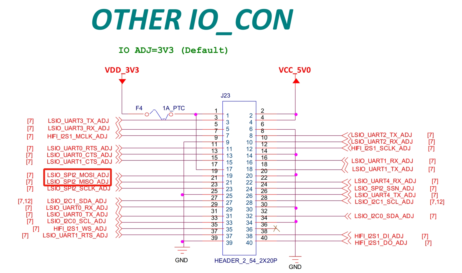
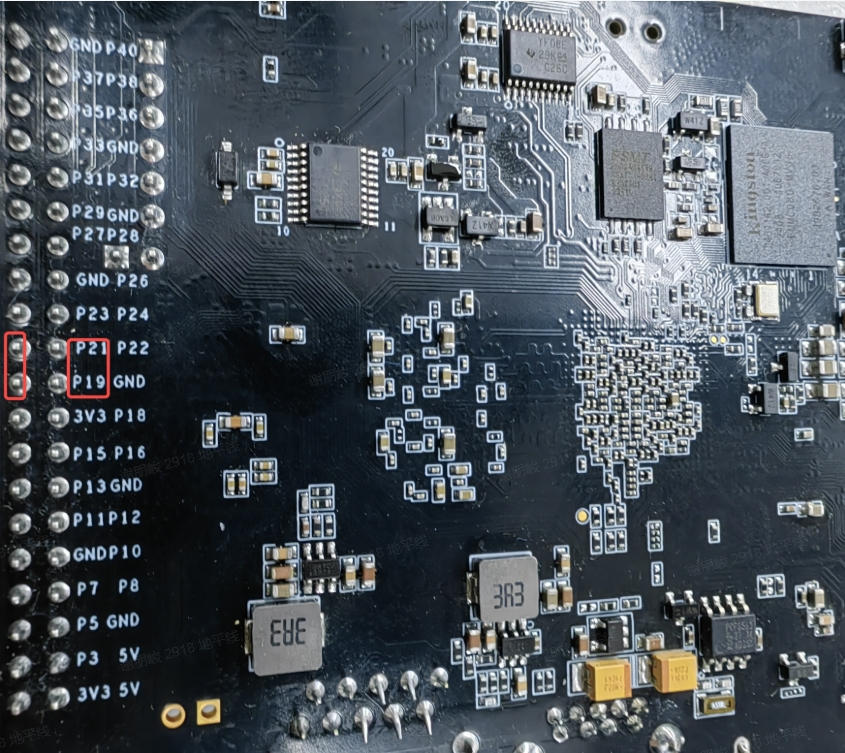
You can prepare another X5_EVB development board and configure it as SPI Slave mode in the device tree. Connect the SPI2_MOSI and SPI2_MISO pins of the board in SPI Master mode to the SPI2_MISO and SPI2_MOSI pins of the board in Slave mode via dual-female jumper wires, and connect the clk, cs, and gnd pins. Execute the command and observe the output as follows:
./spidev_tc -D /dev/spidev0.0 -s 12000000 -I 1 -e 2 -S 32 -v
bits per word: 8
max speed: 1000000 Hz (1000 KHz)
userspace spi write test, len=10 times=1
test, times=0
TX | 67 C6 69 73 51 FF 4A EC 29 CD __ __ __ __ __ __ __ __ __ __ __ __ __ __ __
./spidev_tc -D /dev/spidev0.0 -s 12000000 -I 10 -e 1 -S 32 -v
spi mode: 0x0
bits per word: 8
max speed: 1000000 Hz (1000 KHz)
userspace spi read test, len=10 times=1
test, times=0
RX | 67 C6 69 73 51 FF 4A EC 29 CD __ __ __ __ __ __ __ __ __ __ __ __ __ __ __
Note:
When performing external loopback testing, the SPI Slave program must be executed first, followed by the SPI Master program. If the SPI Master program is executed before the Slave, data loss may occur due to synchronization issues between Master and Slave.
Precautions
1. Refer to the x5_evb schematic to locate the pins and connector positions corresponding to SPI2_MOSI and SPI2_MISO, as shown in the figure:
Connect SPI2_MOSI and SPI2_MISO with dual-female jumper wires. Flip the x5_evb to the backside; the location is shown in the figure:
2. Check the x5_evb device tree and modify SPI2 to support Master functionality:
&spi2 {
  status = "okay";
  pinctrl-names = "default";
  pinctrl-0 = <&pinctrl_spi2>;

  spidev@2 {
  compatible = "dr,x5-spidev";
  spi-max-frequency = <32000000>;
  reg = <0>;
  };
};
To set it to Slave mode, use the following configuration:
&spi2 {
  status = "okay";
  pinctrl-names = "default";
  pinctrl-0 = <&pinctrl_spi2>;
  spi-slave;

  slave@0 {
    compatible = "dr,x5-spidev";
    spi-max-frequency = <32000000>;
    reg = <0>;
  };
}
3. Confirm that the files spistress.sh, spidev_tc.c, and spidev_tc exist in the SDK path app/samples/platform_samples/chip_base_test/05_spi_test, or on the board at root@buildroot:/app/platform_samples/chip_base_test/05_spi_test#.
(base) root@/app/samples/platform_samples/chip_base_test/05_spi_test# tree
.
├── spidev_tc
├── spidev_tc.c
└── spistress.sh
4. If users need to customize test modes and features, it is recommended to recompile the executable in the SDK build environment using the following command:
/opt/arm-gnu-toolchain-11.3.rel1-x86_64-aarch64-none-linux-gnu/bin/aarch64-none-linux-gnu-gcc -o spidev_tc spidev_tc.c
4.5.7.3. Test Method
After completing the preparation, run the test command:
./spistress.sh
After running for a period of time, the log output will be as follows:
root@buildroot:/app/platform_samples/chip_base_test/05_spi_test# ./spistress.sh
SPI test starting...
Test configuration:
  Device: /dev/spidev0.0
  Stress Count: 100
  SPI Speed: 12000000 Hz
  Output Directory: /app/platform_samples/chip_base_test/log
  Log file: /app/platform_samples/chip_base_test/log/spi_test_log3.txt
SPI test completed successfully! Log saved to: /app/platform_samples/chip_base_test/log/spi_test_log3.txt
At this point, if no other information is printed in the log, directly check the spi_test_log1 log file under /app/platform_samples/chip_base_test/log/.
root@buildroot:/app/platform_samples/chip_base_test# cat log/spi_test_log1.txt
spi mode: 0x0
bits per word: 8
max speed: 12000000 Hz (12000 kHz)
Userspace spi read and write test, test_len=32 iterations=100
Test times: 0 Data verification Successful
Test times: 1 Data verification Successful
Test times: 2 Data verification Successful
Test times: 3 Data verification Successful
.....
Test times: 98 Data verification Successful
Test times: 99 Data verification Successful
4.5.7.4. Test Metrics
After the test program starts, the following files will be generated under the directory /app/platform_samples/chip_base_test/log/:
spi_test_log*.txt: Records print information and current status during stress testing.
The test objective is to ensure the system can run stably for 48 hours without rebooting or hanging. To ensure stability during testing, use the following command to check whether abnormal messages such as fail, error, or timeout exist in the log files:
cd "/app/platform_samples/chip_base_test/log/" && grep -iE 'error|fail|timeout' spi_test_log*.txt
SPI Stress Test Results
After running the test script and checking the log files, no abnormal status messages were found, indicating that the stress test passed.
Test times: 97 Data verification Successful
Test times: 98 Data verification Successful
Test times: 99 Data verification Successful