7.5.9 IPC User Guide
This section focuses on the usage instructions for the MCU side. For more details on the principles and usage of IPC, please refer to the IPC Module Introduction section.
Usage Restrictions
- When using the
Ipc_MDMA_SendMsginterface to send data, the data buffer address must be 16-byte aligned. - The send function checks the DMA status via polling. Therefore, DMA interrupts must be disabled before using the send function (disabled by default in the release code). When using the receive function, configure the DMA interrupt and IPC interrupt with the same priority to avoid mutual interruption.
- There are only two IPC MDMA send channels. For single-core or multi-core multi-task sending, it is recommended to use spinlocks or disable interrupts to control DMA resource preemption.
- IPC multi-core sending and receiving are allocated based on Instance, not on Channel.
- IPC initialization must be called after the DMA module is initialized.
- MCU IPC configuration must be consistent with the peer IPC configuration. This includes Instance control segment and data segment addresses, number and IDs of Channels, buffer data, and buffer size. Inconsistent configurations between the two sides will cause IPC communication failure.
- The
receive_coreidin the Instance configuration must specify whether the Instance works on MCU0 or MCU1. If it works on MCU1, configure it asIpc_Receive_Core1. An incorrect configuration will cause IPC communication failure. - The IPC interrupt is enabled on the MCU where the Instance works. If enabled on multiple cores, the interrupt may be preempted by other cores, leading to IPC communication failure.
IPC Configuration
An IPC instance has one or more channels. Instances share the same interrupt. Therefore, an IPC can only be enabled on either MCU0 or MCU1.
When MCU1 uses IPC, two parts need to be configured.
- Configure the callback function. Its purpose is to trigger an interrupt and enter the callback function for processing when the IPC receives a notify signal. Customers can also customize the callback function for data transmission errors. The following example uses Instance0.
static Ipc_ChannelConfigType Ipc_ShmInstance0CfgChannel[8] = {
{
    .ChannelId = 0,
    .ChannelData   = {
        .NumPools = 1,
        .PoolCfg        = Ipc_ShmIpcInstance_0CfgIpcChannel_0BufPool,
        .RxCallback     = IpcTp_InsCan_RxCallback,
        .RxCallbackArg  = (NULL_PTR),
        .TxErrCallback    = DefaultTxErrCallback,
        .TxErrCallbackArg = (NULL_PTR),
    },
},
......
};
- Set
receive_coreid. If it is on MCU1, setreceive_coreid = Ipc_Receive_Core1. Also, ensure that MCU0 has the same IPC settings.
- MCU0 file path:
/mcu/Config/McalCdd/gen_s100_sip_B/Ipc/src/Ipc_Cfg.c - MCU1 file path:
/mcu/Config/McalCdd/gen_s100_sip_B_mcu1/Ipc/src/Ipc_Cfg.c
Ipc_InstanceConfigType Ipc_ShmCfgInstances0 = {
    .Ipc_InstanceId       = 0U,
    .Ipc_ChannelNum       = 8U,
    .LocalCtlAddr         = 0xcdd9e00,
    .RemoteCtlAddr        = 0xcdd9400,
    .CtlShmSize           = 0xa00,
    .LocalDataAddr        = 0xb4080000,
    .RemoteDataAddr       = 0xb4000000,
    .DataShmSize          = 0x80000,
    .SendDmaChanIdx       = 0xffU,
    .Async                = (TRUE),
    .HwInfo               = {
        .Ipc_HwId         = CPU_IPC0,/**< the id of the Hardware */
        .RecvIrqUsed      = (TRUE),/**< Whether to use Recv interrupt */
        .SendMboxId       = 0,/**< the mailbox id */
        .RecvMboxId       = 16,/**< the mailbox id */
        .RemoteIrq        = 16,
        .LocalIrq         = 0,
        .UseMDMA          = (TRUE),
    },
    .Ipc_ChannelConfigPtr = Ipc_ShmInstance0CfgChannel,
    .receive_coreid = Ipc_Receive_Core1,
};
IPC Usage
| MCU IPC Instance | Using Module | Interrupt Func | Opposite End |
|---|---|---|---|
| Ipc_ShmCfgInstances0~8 | User | ISR(Ipc_CpuIpc0Ch0Isr): Ipc_Driver_CpuIpc0ChxIsr() (x=0..8) | Acore instance0~8 |
| Ipc_ShmCfgInstances0/4 | canhal | — | Acore instance0/4 |
| Ipc_ShmCfgInstances5 | External RTC | — | Acore instance5 |
| Ipc_ShmCfgInstances7 | ipcbox | — | Acore instance7 |
| Ipc_ShmCfgInstances8 | mcu1 boot | — | Acore instance8 |
| Ipc_PrivShmCfgInstance0 | Crypto | ISR(Ipc_HsmIpc1Ch4Isr): Ipc_Driver_HSMIpc1Ch4Isr() | HSM |
| Ipc_PrivShmCfgInstance1 | HSM DIAG | ISR(Ipc_HsmIpc1Ch5Isr): Ipc_Driver_HSMIpc1Ch5Isr() | HSM |
| Ipc_PrivShmCfgInstance3 | TimeSync | ISR(Ipc_CpuIpc0Ch10Isr): Ipc_Driver_CpuIpc0Ch10Isr() | Acore Instance10 |
| Ipc_PrivShmCfgInstance4 | Ota | ISR(Ipc_CpuIpc0Ch11Isr): Ipc_Driver_CpuIpc0Ch11Isr() | Acore Instance11 |
| Ipc_PrivShmCfgInstance5 | QGA | ISR(Ipc_CpuIpc0Ch12Isr): Ipc_Driver_CpuIpc0Ch12Isr() | Acore Instance12 |
| Housekeeping | Housekeeping | ISR(Ipc_CpuIpc0Ch15Isr): Housekeeping_IrqHandler() | Acore Housekeeping |
| scmi | scmi | ISR(Ipc_CpuIpc1Ch0Isr): ScmiIpc_Irq0Handler() ISR(Ipc_CpuIpc1Ch1Isr): ScmiIpc_Irq1Handler() ISR(Ipc_CpuIpc1Ch2Isr): ScmiIpc_Irq2Handler() | Acore scmi |
| MCU IPC Instance | Using Module | Interrupt Func | Opposite End |
|---|---|---|---|
| Ipc_ShmCfgInstances0~7 | User | ISR(Ipc0_ChxIsr): Ipc_Driver_MCUIpc0ChxIsr() (x = 0..7) | Acore instance0~7 |
| Ipc_ShmCfgInstances0 / 4 | canhal | — | Acore instance0/4 |
| Ipc_ShmCfgInstances5 | External RTC | — | Acore instance5 |
| Ipc_ShmCfgInstances7 | ipcbox | — | Acore instance7 |
| Ipc_ShmCfgInstances8~15 | User | ISR(Ipc1_ChxIsr): Ipc_Driver_MCUIpc1ChxIsr() (x = 0..7) | Acore instance8~15 (except 8 & 10) |
| Ipc_ShmCfgInstance8 | mcu1 boot | — | Acore instance8 |
| Ipc_ShmCfgInstance10 | timesync | — | Acore instance10 |
| Ipc_PrivShmCfgInstance0 | Crypto | ISR(Ipc_HsmIpc3Ch4Isr): Ipc_Driver_HSMIpc3Ch4Isr() | HSM |
| Ipc_PrivShmCfgInstance1 | HSM Diag | ISR(Ipc_HsmIpc3Ch5Isr): Ipc_Driver_HSMIpc3Ch5Isr() | HSM |
| Ipc_PrivShmCfgInstance2 | Ota | ISR(Ipc0_Ch8Isr): Ipc_Driver_MCUIpc0Ch8Isr() | Acore instance50 |
| Ipc_PrivShmCfgInstance3 | QGA | ISR(Ipc0_Ch9Isr): Ipc_Driver_MCUIpc0Ch9Isr() | Acore instance51 |
| Housekeeping | Housekeeping | ISR(Ipc2_Ch3Isr): Housekeeping_IrqHandler() | Acore Housekeeping |
Application Sample
The application samples all run on the Acore side and communicate with MCU1. Therefore, the MCU1 system must be running before use.
How to run: MCU1 Startup Steps
IpcBox Feature Introduction
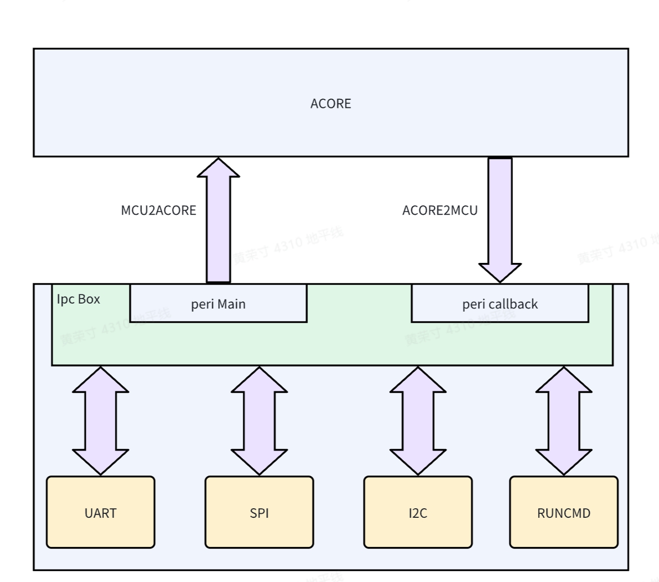
IpcBox is an application extension based on the IPC communication framework on the MCU side. It is used to manage the passthrough functionality of peripherals. The implementation block diagram is as follows:
Various peripherals are managed through a unified interface into the IpcBox. Simply put, peripheral data is forwarded through the IPC Box and returned to the Acore side. Similarly, data from the Acore side is forwarded through the IpcBox to operate the actual peripherals. The data flow is: Acore<->IPC<->MCU<->Peri
Refer to the IPC Module Introduction section for the corresponding Acore side application.
IpcBox underwent a refactoring during the upgrade from version RDKS100 V4.0.4-Beta to RDKS100 V4.0.5-Beta. The changes include the packet structure, IPC channels, and default configuration for passthrough peripherals. Pay attention to the version compatibility between the MCU side and the Acore side.
Passthrough Peripheral Data
Implementation Status:
| Item | Implementation Status | Remarks |
|---|---|---|
| RunCmd | Implemented | None |
| SPI | Implemented | None |
| I2C | Implemented | None |
| Uart | Implemented | Fixed using Uart5 |
Protocol Packet Parsing
Generally, it occupies 128 bytes. The packet length can be extended using data field 2. It is recommended to keep it at 128 bytes so that the data[] array remains 64-byte aligned when allocating 64-byte aligned memory for the packet.
typedef struct {
    uint32 magic; // Magic number
    uint32 version; // Version number
    uint32 checksum; // Checksum
    uint32 length; // Total packet length
    char cmd[MAX_CMD_LENGTH]; // Data field 1
    uint8 reserve[48]; // Reserved
    uint8 data[]; // Data field 2
} IpcBoxPacket_t;
Usage
Since IpcBox occupies peripheral resources, this feature is disabled by default at startup. To use it, enable it manually. There are two ways to enable it:
- Modify the array configuration in the MCU SDK. Find the corresponding peripheral and change
DISABLEtoENABLE.// Service/HouseKeeping/ipc_box/src/ipc_box.c
static Ipcbox_ComType IpcBox_InstanceMap[] = {
{ IPCBOX_COM_ID_RUNCMD, "runcmd", IpcConf_IpcInstance_IpcInstance_7,
IpcConf_IpcInstance_7_IpcChannel_0, ENABLE, IPCBOX_PERIID_INVALID,
IpcBox_RunCmdInit, IpcBox_RunCmdDeinit },
{ IPCBOX_COM_ID_UART, "uart", IpcConf_IpcInstance_IpcInstance_7,
IpcConf_IpcInstance_7_IpcChannel_1, DISABLE, UART5_CHANNEL,
IpcBox_UartInit, IpcBox_UartDeinit },
{ IPCBOX_COM_ID_SPI, "spi", IpcConf_IpcInstance_IpcInstance_7,
IpcConf_IpcInstance_7_IpcChannel_2, DISABLE, IPCBOX_PERIID_INVALID,
IpcBox_SpiInit, IpcBox_SpiDeinit },
{ IPCBOX_COM_ID_I2C, "i2c", IpcConf_IpcInstance_IpcInstance_7,
IpcConf_IpcInstance_7_IpcChannel_3, DISABLE, IPCBOX_PERIID_INVALID,
IpcBox_I2cInit, IpcBox_I2cDeinit },
}; - This is a temporary way to enable it via the MCU1 command line, e.g.:
- Check the status of peripheral passthrough functionality.
D-Robotics:/$ ipcbox_set_mode debug
[066378.758965 0]Module: runcmd, Enable
[066378.759240 0]Module: uart, Enable
[066378.759663 0]Module: spi, Enable
[066378.760075 0]Module: i2c, Enable- Enable and disable IpcBox UART passthrough functionality.
D-Robotics:/$ ipcbox_set_mode uart 1
[066386.990200 0]uart processing enabled
[066386.990487 0]IpcBox_FreeRtos_OsTask_IpcBox_Uart_ASW task is already initialized or running

D-Robotics:/$ ipcbox_set_mode uart 0
[066389.201404 0]uart processing disabled
[066389.267399 0]IpcBox_uart task resources released and terminating
[066389.701820 0]IpcBox_uart task exited properly- Enable and disable IpcBox I2C passthrough functionality.
D-Robotics:/$ ipcbox_set_mode i2c 1
[066394.631826 0]i2c processing enabled
[066394.632101 0]IpcBox_FreeRtos_OsTask_IpcBox_I2c_ASW task is already initialized or running

D-Robotics:/$ ipcbox_set_mode i2c 0
[066397.082288 0]i2c processing disabled
[066397.085213 0]IpcBox_i2c task resources released and terminating
[066397.087215 0]IpcBox_i2c task exited properly- Enable and disable IpcBox SPI passthrough functionality.
D-Robotics:/$ ipcbox_set_mode spi 1
[066403.227424 0]spi processing enabled
[066403.227699 0]IpcBox_Spi task is already initialized or running

D-Robotics:/$ ipcbox_set_mode spi 0
[066406.388582 0]spi processing disabled
[066406.389522 0]IpcBox_spi task resources released and terminating
[066406.393520 0]IpcBox_spi task exited properly
Log Control
Log messages for the IpcBox module can be dynamically toggled using the ipcbox_loglevel command.
D-Robotics:/$ ipcbox_loglevel help
Usage: loglevel <level|subcommand>
  level: 0=NO_LOG, 1=ERROR, 2=WARN, 3=INFO, 4=DEBUG
  subcommands:
    show - show current log level
    help - show this message
Enter ipcbox_loglevel 0 to print the least, and ipcbox_loglevel 4 to print the most.
D-Robotics:/$ ipcbox_loglevel 0
[066736.123326 0]This is an ERROR message

D-Robotics:/$ ipcbox_loglevel 4
[066738.473668 0]Log level changed to 4
[066738.473942 0]This is an ERROR message
[066738.474408 0]This is a WARN message
[066738.474853 0]This is an INFO message
[066738.475309 0]This is a DEBUG message
Implementation of IpcBox RunCmd
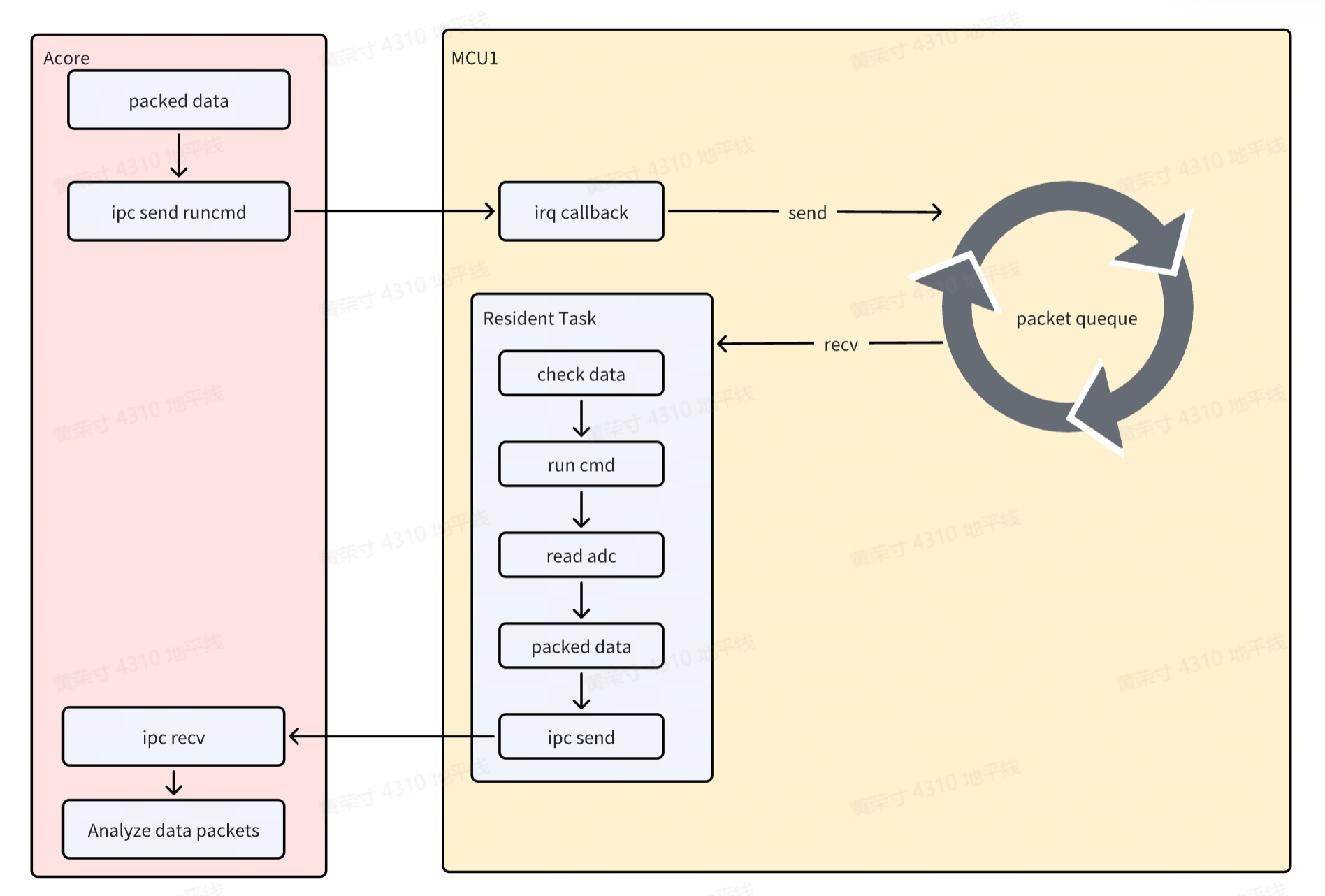
Executes CMD applications on the MCU side based on commands received from the Acore side, referred to as the RunCmd application.
The data forwarding for various peripherals via IPC Box is similar. The implementation principle is mainly divided into the following two processes:
Acore->Ipc->MCUprocess- When Acore sends data to MCU, it triggers an interrupt on the MCU. In the interrupt callback, the data is stored in a queue.
MCU->Ipc->Acoreprocess- There is a resident thread on the MCU that continuously checks if the queue is empty. If not, it validates and parses the data, identifies the CMD command, and runs it.
- The FreeRTOS CMD application is similar to U-Boot CMD commands. This allows users to easily customize their own applications. In this scenario, the executed CMD reads the ADC value and returns it to the Acore via IPC.
Implementation of IpcBox Uart
Similar to the RunCmd implementation, in this scenario, when the MCU sends data to the Acore, it triggers an interrupt on the MCU, but does not use a queue for storage.
The implementation principle is mainly divided into the following two processes:
Acore->Ipc->MCUprocess- When Acore sends data to MCU, it triggers an interrupt on the MCU. The interrupt parses the data and sends it out via the UART peripheral.
MCU->Ipc->Acoreprocess- There is a resident thread on the MCU that continuously calls the UART peripheral to receive data. When data is available, it packages the data and forwards it to the Acore.
Implementation of IpcBox I2c
Similar to the RunCmd implementation, in this scenario, when the MCU sends data to the Acore, it triggers an interrupt on the MCU. In the interrupt callback, the data is stored in a queue and then returned to the Acore via IPC. The implementation principle is mainly divided into the following two processes:
Acore->Ipc->MCUprocess- When Acore sends data to MCU, it triggers an interrupt on the MCU. In the interrupt callback, the data is stored in a queue.
MCU->Ipc->Acoreprocess- There is a resident thread on the MCU that continuously checks if the queue is empty. If not, it validates and parses the data.
- Implements detect/get/set operations based on the command code.
- Since slave devices vary (e.g., address width and operation steps), the implementation of get/set operations differs. Customers need to implement
IpcBox_I2cGetValueandIpcBox_I2cSetValueaccording to the actual scenario. These APIs are located inService/HouseKeeping/ipc_box/src/ipc_i2c.c.
Implementation of IpcBox Spi
Similar to the RunCmd implementation, in this scenario, when the MCU sends data to the Acore, it triggers an interrupt on the MCU. In the interrupt callback, the data is stored in a queue and then returned to the Acore via IPC. The implementation principle is mainly divided into the following two processes:
Acore->Ipc->MCUprocess- When Acore sends data to MCU, it triggers an interrupt on the MCU. In the interrupt callback, the data is stored in a queue.
MCU->Ipc->Acoreprocess- There is a resident thread on the MCU that continuously checks if the queue is empty. If not, it validates and parses the data.
- Performs read/write, read-only, and write-only functions based on the command code. Since SPI is full-duplex communication, read-only actually sends invalid data of the same length, and similarly for write-only.
Application Interface
This section covers the IPC interface on the MCU side.
void Ipc_MDMA_Init(Ipc_InstanceConfigType* pConfigPtr, uint32 InstanceId)
Description:Ipc MDMA Init.

Sync/Async: Synchronous
Parameters(in)
    pConfigPtr:the pointer to the device configuration parameter
    InstanceId:InstanceId id
Parameters(inout)
    None
Parameters(out)
    None
Return value:None
void Ipc_MDMA_DeInit(uint32 InstanceId)
Description:Subsystem driver deinitialization function.

Sync/Async: Synchronous
Parameters(in)
    InstanceId:InstanceId id
Parameters(inout)
    None
Parameters(out)
    None
Return value:None
void Ipc_GetVersionInfo(Std_VersionInfoType * versioninfo)
Description:get driver version.

Sync/Async: Synchronous
Parameters(in)
    None
Parameters(inout)
    versioninfo: the pointer to Version Info
Parameters(out)
    None
Return value:None
Std_ReturnType Ipc_MDMA_CheckRemoteCoreReady(uint32 InstanceId)
Description:check whether remote core is ready.

Sync/Async: Synchronous
Parameters(in)
    InstanceId:InstanceId id
Parameters(inout)
    None
Parameters(out)
    None
Return value:Std_ReturnType
    E_OK: remote core is ready
    IPC_E_PARAM_ERROR: param illegal
    IPC_E_DRIVER_NOT_INIT: Driver is not init
    IPC_E_INSTANCE_NOT_READY_ERROR : remote core is Not ready
    IPC_E_CHANNEL_NOT_OPEN: Instance is not open
Std_ReturnType Ipc_MDMA_SendMsg(uint32 InstanceId, uint32 ChanId, uint32 Size, uint8* Buf, uint32 Timeout)
Description:send message.

Sync/Async: Synchronous
Parameters(in)
    InstanceId: Instance id
    ChanId: channel id
    Size: the size of buf to be sent
    Buf: the pointer to the memory that contains the buf to be sent
    Timeout: timeout(us)
Parameters(inout)
    None
Parameters(out)
    None
Return value:Std_ReturnType
    E_OK: success
    IPC_E_PARAM_ERROR: param is illegal
    IPC_E_DRIVER_NOT_INIT: Driver is not init
    IPC_E_CHANNEL_NOT_OPEN: Instance is not open
    IPC_E_TIMEOUT_ERROR: send timeout
    IPC_E_NO_MEMORY_ERROR: no memory to send buf
    IPC_E_CHECKRESERROR: check resource error
DMA hardware requires the transfer address to be 16-byte aligned. The buffer should be defined as follows, with the start address and size 16-byte aligned: static uint8 __attribute__((aligned(16))) Ipc_Send_Buf[8192];
Std_ReturnType Ipc_MDMA_PollMsg(uint32 InstanceId)
Description:poll message If the Instance does not receive data using interrupts.

Sync/Async: Synchronous
Parameters(in)
    InstanceId: Instance id
Parameters(inout)
    None
Parameters(out)
    None
Return value:Std_ReturnType
    E_OK: success
    IPC_E_PARAM_ERROR: param is illegal
    IPC_E_DRIVER_NOT_INIT: Driver is not init
    IPC_E_CHANNEL_NOT_OPEN: Instance is not open
    IPC_E_NO_DATA_TO_RECEIVE_ERROR: No data to be received
Std_ReturnType Ipc_MDMA_OpenInstance(uint32 InstanceId)
Description:Open a Instance pointed to by ID.

Sync/Async: Synchronous
Parameters(in)
    InstanceId: Instance id
Parameters(inout)
    None
Parameters(out)
    None
Return value:Std_ReturnType
    E_OK: success
    IPC_E_DRIVER_NOT_INIT: Driver is not init
    IPC_E_CHANNEL_NOT_CLOSE: Instance has been opened
    IPC_E_PARAM_ERROR param is illegal
Std_ReturnType Ipc_MDMA_CloseInstance(uint32 InstanceId)
Description:close a Instance pointed to by ID.

Sync/Async: Synchronous
Parameters(in)
    InstanceId: Instance id
Parameters(inout)
    None
Parameters(out)
    None
Return value:Std_ReturnType
    E_OK: success
    IPC_E_DRIVER_NOT_INIT: Driver is not init
    IPC_E_CHANNEL_NOT_CLOSE: Instance has been opened
    IPC_E_PARAM_ERROR param is illegal
Std_ReturnType Ipc_MDMA_TryGetHwResource(uint32 InstanceId, uint32 ChanId, uint32 BufSize)
Description:try get Hardware resource.

Sync/Async: Synchronous
Parameters(in)
    InstanceId ChanId BufSize: Instance id Chanel Id buf size
Parameters(inout)
    None
Parameters(out)
    None
Return value:Std_ReturnType
    E_OK: success
    IPC_E_DRIVER_NOT_INIT: Driver is not init
    IPC_E_DEVICE_BUSY: Instance is busy.
    IPC_E_MDMA_BUSY: Send MDMA is busy.
    IPC_E_NO_BUF_ERROR: no buffer
    IPC_E_CHANNEL_NOT_OPEN: Instance has been closed