7.5.15 ICU User Guide
The ICU module is a software submodule based on the S100 chip solution and serves as basic service software in the overall system. In the S100 overall design, ICU software mainly abstracts and uniformly manages hardware with input capture capabilities in the system. Hardware-layer IPs include PWM and GPIO. This document focuses on GPIO interrupt configuration and implementation.
GPIO Interrupt User Guide
In the S100 MCU, GPIO has four IO groups: GPIO0, GPIO1, GPIO2, and GPIO_AON. The first three groups provide 88 pins in total, while the GPIO_AON group provides 12 pins. Refer to mcu/Config/McalCdd/gen_s100_sip_B_mcu1/Port/src/Port_PBcfg.c for details. All pins support the following interrupt trigger modes: rising edge, falling edge, both edges, and high/low level trigger.
| ISR Function | IRQ | IRQ Define | Description |
|---|---|---|---|
| Gpio0_ExtIsr | 68 | MCUSYS_GPIO0_INTR | Gpio Mode |
| Gpio1_ExtIsr | 69 | MCUSYS_GPIO1_INTR | Gpio Mode |
| Gpio2_ExtIsr | 70 | MCUSYS_GPIO2_INTR | Gpio Mode |
| Gpio3_ExtIsr | 361 | AON_WAKEUP_GPIO_INTR | Gpio Mode |
Port Configuration
Each pin on the S100 MCU supports at least one function. Therefore, before using GPIO interrupts, you must configure the pin function and attributes through the Port subsystem, which is the pin remapping process. Take GPIO_MCU[20] and GPIO_MCU[21] as examples. The functions of these two pins are as follows:
| FUNC0 | IO TYPE0 | FUNC1 | IO TYPE1 | FUNC2 | IO TYPE2 | FUNC3 | IO TYPE3 |
|---|---|---|---|---|---|---|---|
| SPI3_CSN0 | O | DEBUG_OUT5 | O | TRC_CTL | O | GPIO_MCU[20] | IO |
| SPI3_CSN1 | IO | PPS_IN0 | I | TRC_CLK | O | GPIO_MCU[21] | IO |
Configure both pins to FUNC3, that is, GPIO mode. For Port introduction and usage, refer to Port User Guide and Port Development Guide. The configuration file is mcu/Config/McalCdd/gen_s100_sip_B_mcu1/Port/src/Port_PBcfg.c.
static const Port_Lld_PinConfigType Port_McuPinConfigs[PORT_MCU_MAX_NUM]=
{
    ...
    /* Pin Id,  Pin name,      IsUsed,        ModeChang,    SchmittTriger,  InputEnable,     IsUsedGpio,     DirChang,   PinMode,    Config Type,        Pull Type,       Drive Strength,         GpioDir,           GpioData*/
    {(uint8)20, "SPI3_CSN0", (boolean)TRUE, {(boolean)TRUE, (boolean)FALSE, (boolean)TRUE, (boolean)TRUE, (boolean)FALSE, GPIO, PORT_PIN_CONFIG_TYPE0, PORT_PULL_UP, PORT_DRIVE_DEFAULT, PORT_PIN_DIR_IN, PORT_PIN_LEVEL_LOW}},
    /* Pin Id,  Pin name,      IsUsed,        ModeChang,    SchmittTriger,  InputEnable,     IsUsedGpio,     DirChang,   PinMode,    Config Type,        Pull Type,       Drive Strength,         GpioDir,           GpioData*/
    {(uint8)21, "PWR_SHDN_N", (boolean)TRUE, {(boolean)TRUE, (boolean)FALSE, (boolean)TRUE, (boolean)TRUE, (boolean)FALSE, GPIO, PORT_PIN_CONFIG_TYPE0, PORT_PULL_UP, PORT_DRIVE_DEFAULT, PORT_PIN_DIR_IN, PORT_PIN_LEVEL_LOW}},
    ...
}
ICU Configuration
ICU file list:
- mcu/McalCdd/Icu/src/Icu_Lld_Gpio.c
- mcu/McalCdd/Icu/src/Icu_Lld.c
- mcu/McalCdd/Icu/src/Icu.c
- mcu/McalCdd/Icu/inc/Icu_Lld_Gpio.h
- mcu/McalCdd/Icu/inc/Icu_Lld.h
- mcu/McalCdd/Icu/inc/Icu_Types.h
- mcu/McalCdd/Icu/inc/Icu.h
GPIO interrupt functionality is managed uniformly by ICU. Detailed pin attributes (such as interrupt type and callback functions) must be configured through ICU. The configuration file is mcu/Config/McalCdd/gen_s100_sip_B_mcu1/Icu/src/Icu_PBCfg.c. Configuration is done by modifying structures such as Icu_ConfigType, Icu_Lld_IpConfigType, Gpio_Icu_IpConfigType, Icu_Lld_ChannelConfigType, Icu_ChannelConfigType, and Gpio_Icu_ChannelConfigType. Among them, Gpio_Icu_ChannelConfigType is the key structure responsible for defining interrupt callback functions, trigger types, interrupt mask bits, and more.
Icu_ConfigType
#define ICU_CONF_IPS_PB 1
#define ICU_CONF_CHS_PB 2

/** @brief Array of configured Icu channels */
const Icu_ConfigType Icu_Config = {
    /** @brief Number of configured Icu ips */
    .nNumInstances = ICU_CONF_IPS_PB,
    /** @brief Number of configured Icu channels */
    .NumChannels = ICU_CONF_CHS_PB,
    /** @brief Number of configured Icu channels */
    .Icu_ChannelConfigPtr = Icu_ChConfig_PB,
    /** @brief Pointer to array of Icu channels */
    .Icu_LldConfigPtr = Icu_Lld_IpConfig_PB,
};
| Parameter | Description |
|---|---|
| nNumInstances | Number of GPIO controller instances |
| NumChannels | Number of channels (or pins) |
| Icu_ChannelConfigPtr | Pointer to the Icu_ChannelConfigType structure |
| Icu_LldConfigPtr | Pointer to the Icu_Lld_IpConfigType structure |
Icu_Lld_IpConfigType
#define ICU_CONF_IPS_PB 1

/** @brief Array of high level Icu channel Config Type*/
static Icu_Lld_IpConfigType Icu_Lld_IpConfig_PB[ICU_CONF_IPS_PB] = {
    /** @brief gpio module 0 */
    {
        /**< id of gpio icu module in the Icu configuration */
        .instanceNo = 0,
        /**< The IP type used. */
        .InstanceMode = ICU_GPIO_MODULE,
        /**< gpio IP configure type. */
        .GpioConfig = &Icu_Gpio_IpConfig_PB[0],
    },
};
| Parameter | Description |
|---|---|
| instanceNo | Controller instance (e.g., 0 - GPIO0) |
| InstanceMode | GPIO or PWM mode |
| GpioConfig | Pointer to the Icu_Lld_ChannelConfigType structure |
Gpio_Icu_IpConfigType
#define ICU_GPIO_CONF_MODS_PB 1

/** @brief Array of gpio Icu ip Config Type channels */
static Gpio_Icu_IpConfigType Icu_Gpio_IpConfig_PB[ICU_GPIO_CONF_MODS_PB] = {
    /** @brief gpio module 1 */
    {
        /**< Number of gpio channels in the Icu configuration */
        .NumChannels = 2,
        /**< The Instance index used for the configuration of channel */
        .instanceNo = 0,
        /**< id of gpio icu module in the Icu configuration */
        .ChannelsConfig = Icu_Gpio_ChannelConfig_PB[0],
    },
};
| Parameter | Description |
|---|---|
| NumChannels | Number of channels |
| instanceNo | Controller instance (e.g., 0 - GPIO0) |
| ChannelsConfig | Pointer to the Gpio_Icu_ChannelConfigType structure |
Icu_ChannelConfigType
#define ICU_CONF_CHS_PB 2

/** @brief Array of high level Icu channel Config Type*/
static Icu_ChannelConfigType Icu_ChConfig_PB[ICU_CONF_CHS_PB] = {
    /** @brief icu CH 0 */
    {
        /** Assigned ICU channel id*/
        .ChannelId = 0,
        /** @brief Pointer to the lld gpio channel pointer configuration, gpio 4 channel 0 */
        .Icu_LldChannelConfigPtr = &Icu_Lld_Gpio_ChannelConfig_PB[0][0],
    },
    /** @brief icu CH 1 */
    {
        /** Assigned ICU channel id*/
        .ChannelId = 1,
        /** @brief Pointer to the lld gpio channel pointer configuration, gpio 4 channel 1 */
        .Icu_LldChannelConfigPtr = &Icu_Lld_Gpio_ChannelConfig_PB[0][1],
    },
};
| Parameter | Description |
|---|---|
| ChannelId | Channel identifier |
| Icu_LldChannelConfigPtr | Pointer to the Icu_Lld_ChannelConfigType structure |
Icu_Lld_ChannelConfigType
#define ICU_GPIO_CONF_MODS_PB 1

/** @brief Array of Gpio Channel ConfigType channels*/
static Icu_Lld_ChannelConfigType Icu_Lld_Gpio_ChannelConfig_PB[ICU_GPIO_CONF_MODS_PB][32] = {
    /** @brief gpio module 0 */
    {
        /** @brief gpio mod 0 channel 20 */
        {
            .ChannelMode = ICU_GPIO_MODULE,
            .instanceNo = 0,
            .gpioHwChannelConfig = &Icu_Gpio_ChannelConfig_PB[0][0],
        },
        /** @brief gpio mod 0 channel 21 */
        {
            .ChannelMode = ICU_GPIO_MODULE,
            .instanceNo = 0,
            .gpioHwChannelConfig = &Icu_Gpio_ChannelConfig_PB[0][1],
        },
    },
};
| Parameter | Description |
|---|---|
| ChannelMode | GPIO or PWM mode |
| instanceNo | Controller instance (e.g., 0 - GPIO0) |
| gpioHwChannelConfig | Pointer to the Gpio_Icu_ChannelConfigType structure |
Gpio_Icu_ChannelConfigType
#define ICU_GPIO_CONF_MODS_PB 1

extern void Icu_Gpio_Channel_0_20_ISR(void);
extern void Icu_Gpio_Channel_0_21_ISR(void);

/** @brief Array of Gpio Channel ConfigType channels*/
static Gpio_Icu_ChannelConfigType Icu_Gpio_ChannelConfig_PB[ICU_GPIO_CONF_MODS_PB][32] = {
    /** @brief gpio module 0 */
    {
        /** @brief gpio mod 0 channel 20 */
        {
            /**< Assigned GPIO channel id*/
            .PinId = 20,
            /**< Assigned GPIO ip id*/
            .instanceNo = 0,
            /**< GPIO Default Start Edge */
            .DefaultStartEdge = GPIO_ICU_FALLING_EDGE,
            /**< Notification Enable.*/
            .NotificationEnable = TRUE,
            /**< The notification functions shall have no parameters and no return value.*/
            .GpioChannelNotification = Icu_Gpio_Channel_0_20_ISR,
            /**< Interrupt Enable or Disable . */
            .IntEnable = TRUE,
            /**< Interrupt Mask or Umask . */
            .IntMask = FALSE,
        },
        /** @brief gpio mod 0 channel 21 */
        {
            /**< Assigned GPIO channel id*/
            .PinId = 21,
            /**< Assigned GPIO ip id*/
            .instanceNo = 0,
            /**< GPIO Default Start Edge */
            .DefaultStartEdge = GPIO_ICU_FALLING_EDGE,
            /**< Notification Enable.*/
            .NotificationEnable = TRUE,
            /**< The notification functions shall have no parameters and no return value.*/
            .GpioChannelNotification = Icu_Gpio_Channel_0_21_ISR,
            /**< Interrupt Enable or Disable . */
            .IntEnable = TRUE,
            /**< Interrupt Mask or Umask . */
            .IntMask = FALSE,
        },
    },
};
| Parameter | Description |
|---|---|
| PinId | Pin number (or channel number) |
| instanceNo | Controller instance (e.g., 0 - GPIO0) |
| DefaultStartEdge | Interrupt trigger mode: 1. Falling edge 2. Rising edge 3. Rising or falling edge 4. High level 5. Low level |
| NotificationEnable | Whether to enable the callback |
| GpioChannelNotification | Callback function pointer (no parameters, no return value) |
| IntEnable | Whether to enable the interrupt: - TRUE: Enable interrupt- FALSE: Disable interrupt |
| IntMask | Whether to mask the interrupt: - TRUE: Mask interrupt- FALSE: Do not mask interrupt |
Both IntEnable and IntMask are used for interrupt on/off control. The difference is:
IntEnable: When set toFALSE, interrupts are fundamentally disabled and the interrupt status register will not be set.IntMask: When set toTRUE, only the interrupt signal to the CPU is blocked; the interrupt event still occurs and the status register is still set.
Configuration recommendations:
- To enable interrupts:
IntEnable = TRUEandIntMask = FALSE. - To disable interrupts:
IntEnable = FALSEandIntMask = TRUE.
The callback function is the final entry point after an interrupt is triggered. The complete flow is: interrupt handler -> ICU interrupt handler -> callback function.
NotificationEnable controls whether the callback function is executed. Setting it to FALSE skips the callback but does not affect interrupt occurrence or flag generation. To fully enable interrupts and callbacks, ensure NotificationEnable = TRUE, IntEnable = TRUE, IntMask = FALSE, and GpioChannelNotification points to a specific callback function. It is recommended that callback function names reflect their instance and channel, such as Icu_Gpio_Channel_0_20_ISR. The callback functions are defined in mcu/samples/Interrupt/src/gpio_Interrupt_test.c:
/** GPIO_MCU[20] interrupt callback function */
void Icu_Gpio_Channel_0_20_ISR(void)
{
    LogSync("enter Icu_Gpio_Channel_0_20_ISR!!!\r\n");
    /** Add user code here */
}

/** GPIO_MCU[21] interrupt callback function */
void Icu_Gpio_Channel_0_21_ISR(void)
{
    LogSync("enter Icu_Gpio_Channel_0_21_ISR!!!\r\n");
    /** Add user code here */
}
Note that users only need to implement business logic in the callback function. There is no need to manually clear interrupt flags; this is handled automatically by the ICU driver.
Interrupt Implementation
Before configuring interrupts, you must identify the IRQ number and interrupt entry function bound to the target pin. Based on the MCU GPIO interrupt resources described above, pins GPIO_MCU[20] and GPIO_MCU[21] share the interrupt entry function Gpio0_ExtIsr, with IRQ number 68. Interrupt registration, priority configuration, and enablement are defined in the source file mcu/McalCdd/Icu/src/Icu_Lld_Gpio.c.
void Icu_Gpio_Interrupt_Init(uint8 Instance, uint8 priority)
{
    uint8 cmd = Instance;

    switch (cmd) {
    case 0:
        INT_SYS_InstallHandler(MCUSYS_GPIO0_INTR, Gpio0_ExtIsr, 0);
        INT_SYS_SetPriority(MCUSYS_GPIO0_INTR, priority);
        INT_SYS_EnableIRQ(MCUSYS_GPIO0_INTR);
        break;
    case 1:
        INT_SYS_InstallHandler(MCUSYS_GPIO1_INTR, Gpio1_ExtIsr, 0);
        INT_SYS_SetPriority(MCUSYS_GPIO1_INTR, priority);
        INT_SYS_EnableIRQ(MCUSYS_GPIO1_INTR);
        break;
    case 2:
        INT_SYS_InstallHandler(MCUSYS_GPIO2_INTR, Gpio2_ExtIsr, 0);
        INT_SYS_SetPriority(MCUSYS_GPIO2_INTR, priority);
        INT_SYS_EnableIRQ(MCUSYS_GPIO2_INTR);
        break;
    case 3:
        INT_SYS_InstallHandler(AON_WAKEUP_GPIO_INTR, Gpio3_ExtIsr, 0);
        INT_SYS_SetPriority(AON_WAKEUP_GPIO_INTR, priority);
        INT_SYS_EnableIRQ(AON_WAKEUP_GPIO_INTR);
        break;
    default:
        break;
    }
}

void Icu_Gpio_Interrupt_DeInit(uint8 Instance)
{
    uint8 cmd = Instance;

    switch (cmd) {
    case 0:
        INT_SYS_DisableIRQ(MCUSYS_GPIO0_INTR);
        break;
    case 1:
        INT_SYS_DisableIRQ(MCUSYS_GPIO1_INTR);
        break;
    case 2:
        INT_SYS_DisableIRQ(MCUSYS_GPIO2_INTR);
        break;
    case 3:
        INT_SYS_DisableIRQ(AON_WAKEUP_GPIO_INTR);
        break;
    default:
        break;
    }
}
Users only need to call Icu_Gpio_Interrupt_Init and Icu_Gpio_Interrupt_DeInit to enable and disable interrupts. The related implementation is located in mcu/samples/Interrupt/src/gpio_Interrupt_test.c.
/** init interrupt */
Icu_Gpio_Interrupt_Init(0, 30);

/** deinit interrupt */
Icu_Gpio_Interrupt_DeInit(0);
GPIO Interrupt Sample
Initialize GPIO interrupts on the MCU1 serial port:
D-Robotics:/$ gpio_interrupt on
[0975.377836 0]INFO: Start gpio_interrupt test...
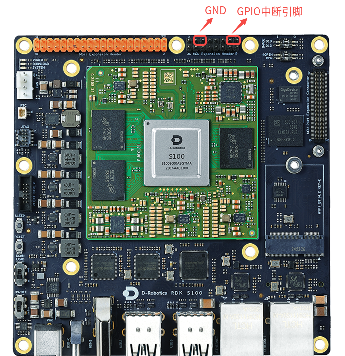
Connect one end of a jumper wire to the two GPIO pins shown below and the other end to ground.
If the serial port prints the following, the GPIO interrupt was triggered successfully:
# GPIO_MCU[20] callback function: 0-instanceNo, 20-PinId
[0667.710363 0]INFO: Enter Icu_Gpio_Channel_0_20_ISR!!!

# GPIO_MCU[21] callback function: 0-instanceNo, 21-PinId
[0593.171002 0]INFO: Enter Icu_Gpio_Channel_0_21_ISR!!!
Disable GPIO interrupts as follows:
D-Robotics:/$ gpio_interrupt off
[0673.558143 0]INFO: Stop gpio_interrupt test
The ICU module is a software submodule based on the S600 chip solution and serves as basic service software in the overall system. In the S600 overall design, ICU software mainly abstracts and uniformly manages hardware with input capture capabilities in the system. Hardware-layer IPs include PWM and GPIO. This document focuses on GPIO interrupt configuration and implementation.
GPIO Interrupt User Guide
In the S600 MCU, GPIO has five IO groups: GPIO0, GPIO1, GPIO2, GPIO3, and GPIO_AON. The GPIO groups provide 105 pins in total, while the GPIO_AON group provides 42 pins. Refer to mcu/Config/McalCdd/gen_S600_sip_B_mcu1/Port/src/Port_PBcfg.c for details. All pins support the following interrupt trigger modes: rising edge, falling edge, both edges, and high/low level trigger.
| ISR Function | IRQ | IRQ Define | Description |
|---|---|---|---|
| Gpio0_ExtIsr | 89 | MCUSYS_GPIO0_INTR | Gpio Mode |
| Gpio1_ExtIsr | 90 | MCUSYS_GPIO1_INTR | Gpio Mode |
| Gpio2_ExtIsr | 91 | MCUSYS_GPIO2_INTR | Gpio Mode |
| Gpio3_ExtIsr | 92 | MCUSYS_GPIO3_INTR | Gpio Mode |
| Gpio4_ExtIsr | 371 | AON_GPIO_INTR | Gpio Mode |
Port Configuration
Each pin on the S600 MCU supports at least one function. Therefore, before using GPIO interrupts, you must configure the pin function and attributes through the Port subsystem, which is the pin remapping process. Take GPIO_MCU[52] and GPIO_MCU[53] as examples. The functions of these two pins are as follows:
| FUNC0 | IO TYPE0 | FUNC1 | IO TYPE1 | FUNC2 | IO TYPE2 | FUNC3 | IO TYPE3 |
|---|---|---|---|---|---|---|---|
| PWM4_IO | IO | SPI11_MISO | I | USS_PWM17 | IO | GPIO_MCU[52] | IO |
| PWM5_IO | IO | SPI11_SCLK | O | USS_PWM18 | IO | GPIO_MCU[53] | IO |
Configure both pins to FUNC3, that is, GPIO mode. For Port introduction and usage, refer to Port User Guide and Port Development Guide. The configuration file is mcu/Config/McalCdd/gen_s600_md/Port/src/Port_PBcfg.c.
static const Port_Lld_PinConfigType Port_McuPinConfigs[PORT_MCU_MAX_NUM]=
{
    ...
    /* Pin Id,  Pin name,      IsUsed,        ModeChang,    SchmittTriger,  InputEnable,     IsUsedGpio,     DirChang,   PinMode,    Config Type,        Pull Type,       Drive Strength,         GpioDir,           GpioData*/
    {(uint8)52, "ICU_GPIO1", (boolean)TRUE, {(boolean)TRUE, (boolean)FALSE, (boolean)TRUE, (boolean)TRUE, (boolean)TRUE, GPIO, PORT_PIN_CONFIG_TYPE0, PORT_PULL_DOWN, PORT_DRIVE_DEFAULT, PORT_PIN_DIR_IN, PORT_PIN_LEVEL_LOW}},
    /* Pin Id,  Pin name,      IsUsed,        ModeChang,    SchmittTriger,  InputEnable,     IsUsedGpio,     DirChang,   PinMode,    Config Type,        Pull Type,       Drive Strength,         GpioDir,           GpioData*/
    {(uint8)53, "ICU_GPIO2", (boolean)TRUE, {(boolean)TRUE, (boolean)FALSE, (boolean)TRUE, (boolean)TRUE, (boolean)TRUE, GPIO, PORT_PIN_CONFIG_TYPE0, PORT_PULL_DOWN, PORT_DRIVE_DEFAULT, PORT_PIN_DIR_IN, PORT_PIN_LEVEL_LOW}},
    ...
}
ICU Configuration
ICU file list:
- mcu/McalCdd/Icu/src/Icu_Lld_Gpio.c
- mcu/McalCdd/Icu/src/Icu_Lld.c
- mcu/McalCdd/Icu/src/Icu.c
- mcu/McalCdd/Icu/inc/Icu_Lld_Gpio.h
- mcu/McalCdd/Icu/inc/Icu_Lld.h
- mcu/McalCdd/Icu/inc/Icu_Types.h
- mcu/McalCdd/Icu/inc/Icu.h
GPIO interrupt functionality is managed uniformly by ICU. Detailed pin attributes (such as interrupt type and callback functions) must be configured through ICU. The configuration file is mcu/Config/McalCdd/gen_s600_md_mcu1/Icu/src/Icu_PBCfg.c. Configuration is done by modifying structures such as Icu_ConfigType, Icu_Lld_IpConfigType, Gpio_Icu_IpConfigType, Icu_Lld_ChannelConfigType, Icu_ChannelConfigType, and Gpio_Icu_ChannelConfigType. Among them, Gpio_Icu_ChannelConfigType is the key structure responsible for defining interrupt callback functions, trigger types, interrupt mask bits, and more.
Icu_ConfigType
#define ICU_CONF_IPS_PB 1
#define ICU_CONF_CHS_PB 2

/** @brief Array of configured Icu channels */
const Icu_ConfigType Icu_Config = {
    /** @brief Number of configured Icu ips */
    .nNumInstances = ICU_CONF_IPS_PB,
    /** @brief Number of configured Icu channels */
    .NumChannels = ICU_CONF_CHS_PB,
    /** @brief Number of configured Icu channels */
    .Icu_ChannelConfigPtr = Icu_ChConfig_PB,
    /** @brief Pointer to array of Icu channels */
    .Icu_LldConfigPtr = Icu_Lld_IpConfig_PB,
};
| Parameter | Description |
|---|---|
| nNumInstances | Number of GPIO controller instances |
| NumChannels | Number of channels (or pins) |
| Icu_ChannelConfigPtr | Pointer to the Icu_ChannelConfigType structure |
| Icu_LldConfigPtr | Pointer to the Icu_Lld_IpConfigType structure |
Icu_Lld_IpConfigType
#define ICU_CONF_IPS_PB 1

/** @brief Array of high level Icu channel Config Type*/
static Icu_Lld_IpConfigType Icu_Lld_IpConfig_PB[ICU_CONF_IPS_PB] = {
    /** @brief gpio module 1 */
    {
        /**< id of gpio icu module in the Icu configuration */
        .instanceNo = 1,
        /**< The IP type used. */
        .InstanceMode = ICU_GPIO_MODULE,
        /**< gpio IP configure type. */
        .GpioConfig = &Icu_Gpio_IpConfig_PB[0],
    },
};
| Parameter | Description |
|---|---|
| instanceNo | Controller instance (e.g., 1 - GPIO1) |
| InstanceMode | GPIO or PWM mode |
| GpioConfig | Pointer to the Icu_Lld_ChannelConfigType structure |
Gpio_Icu_IpConfigType
#define ICU_GPIO_CONF_MODS_PB 1

/** @brief Array of gpio Icu ip Config Type channels */
static Gpio_Icu_IpConfigType Icu_Gpio_IpConfig_PB[ICU_GPIO_CONF_MODS_PB] = {
    /** @brief gpio module 1 */
    {
        /**< Number of gpio channels in the Icu configuration */
        .NumChannels = 2,
        /**< The Instance index used for the configuration of channel */
        .instanceNo = 1,
        /**< id of gpio icu module in the Icu configuration */
        .ChannelsConfig = Icu_Gpio_ChannelConfig_PB[0],
    },
};
| Parameter | Description |
|---|---|
| NumChannels | Number of channels |
| instanceNo | Controller instance (e.g., 0 - GPIO0) |
| ChannelsConfig | Pointer to the Gpio_Icu_ChannelConfigType structure |
Icu_ChannelConfigType
#define ICU_CONF_CHS_PB 2

/** @brief Array of high level Icu channel Config Type*/
static Icu_ChannelConfigType Icu_ChConfig_PB[ICU_CONF_CHS_PB] = {
    /** @brief icu CH 0 */
    {
        /** Assigned ICU channel id*/
        .ChannelId = 0,
        /** @brief Pointer to the lld gpio channel pointer configuration, gpio 4 channel 0 */
        .Icu_LldChannelConfigPtr = &Icu_Lld_Gpio_ChannelConfig_PB[0][0],
    },
    /** @brief icu CH 1 */
    {
        /** Assigned ICU channel id*/
        .ChannelId = 1,
        /** @brief Pointer to the lld gpio channel pointer configuration, gpio 4 channel 1 */
        .Icu_LldChannelConfigPtr = &Icu_Lld_Gpio_ChannelConfig_PB[0][1],
    },
};
| Parameter | Description |
|---|---|
| ChannelId | Channel identifier |
| Icu_LldChannelConfigPtr | Pointer to the Icu_Lld_ChannelConfigType structure |
Icu_Lld_ChannelConfigType
#define ICU_GPIO_CONF_MODS_PB 1

/** @brief Array of Gpio Channel ConfigType channels*/
static Icu_Lld_ChannelConfigType Icu_Lld_Gpio_ChannelConfig_PB[ICU_GPIO_CONF_MODS_PB][32] = {
    /** @brief gpio module 1 */
    {
        /** @brief gpio mod 1 channel 20 */
        {
            .ChannelMode = ICU_GPIO_MODULE,
            .instanceNo = 1,
            .gpioHwChannelConfig = &Icu_Gpio_ChannelConfig_PB[0][0],
        },
        /** @brief gpio mod 1 channel 21 */
        {
            .ChannelMode = ICU_GPIO_MODULE,
            .instanceNo = 1,
            .gpioHwChannelConfig = &Icu_Gpio_ChannelConfig_PB[0][1],
        },
    },
};
| Parameter | Description |
|---|---|
| ChannelMode | GPIO or PWM mode |
| instanceNo | Controller instance (e.g., 1 - GPIO1) |
| gpioHwChannelConfig | Pointer to the Gpio_Icu_ChannelConfigType structure |
Gpio_Icu_ChannelConfigType
#define ICU_GPIO_CONF_MODS_PB 1

extern void Icu_Gpio_Channel_0_20_ISR(void);
extern void Icu_Gpio_Channel_0_21_ISR(void);

/** @brief Array of Gpio Channel ConfigType channels*/
static Gpio_Icu_ChannelConfigType Icu_Gpio_ChannelConfig_PB[ICU_GPIO_CONF_MODS_PB][32] = {
    /** @brief gpio module 1 */
    {
        /** @brief gpio mod 1 channel 20 */
        {
            /**< Assigned GPIO channel id*/
            .PinId = 20,
            /**< Assigned GPIO ip id*/
            .instanceNo = 1,
            /**< GPIO Default Start Edge */
            .DefaultStartEdge = GPIO_ICU_BOTH_EDGES,
            /**< Notification Enable.*/
            .NotificationEnable = TRUE,
            /**< The notification functions shall have no parameters and no return value.*/
            .GpioChannelNotification = Icu_Gpio_Channel_1_20_ISR,
            /**< Interrupt Enable or Disable . */
            .IntEnable = TRUE,
            /**< Interrupt Mask or Umask . */
            .IntMask = FALSE,
        },
        /** @brief gpio mod 1 channel 21 */
        {
            /**< Assigned GPIO channel id*/
            .PinId = 21,
            /**< Assigned GPIO ip id*/
            .instanceNo = 1,
            /**< GPIO Default Start Edge */
            .DefaultStartEdge = GPIO_ICU_BOTH_EDGES,
            /**< Notification Enable.*/
            .NotificationEnable = TRUE,
            /**< The notification functions shall have no parameters and no return value.*/
            .GpioChannelNotification = Icu_Gpio_Channel_1_21_ISR,
            /**< Interrupt Enable or Disable . */
            .IntEnable = TRUE,
            /**< Interrupt Mask or Umask . */
            .IntMask = FALSE,
        },
    },
};
| Parameter | Description |
|---|---|
| PinId | Pin number (or channel number) |
| instanceNo | Controller instance (e.g., 0 - GPIO0) |
| DefaultStartEdge | Interrupt trigger mode: 1. Falling edge 2. Rising edge 3. Rising or falling edge 4. High level 5. Low level |
| NotificationEnable | Whether to enable the callback |
| GpioChannelNotification | Callback function pointer (no parameters, no return value) |
| IntEnable | Whether to enable the interrupt: - TRUE: Enable interrupt- FALSE: Disable interrupt |
| IntMask | Whether to mask the interrupt: - TRUE: Mask interrupt- FALSE: Do not mask interrupt |
Both IntEnable and IntMask are used for interrupt on/off control. The difference is:
IntEnable: When set toFALSE, interrupts are fundamentally disabled and the interrupt status register will not be set.IntMask: When set toTRUE, only the interrupt signal to the CPU is blocked; the interrupt event still occurs and the status register is still set.
Configuration recommendations:
- To enable interrupts:
IntEnable = TRUEandIntMask = FALSE. - To disable interrupts:
IntEnable = FALSEandIntMask = TRUE.
The callback function is the final entry point after an interrupt is triggered. The complete flow is: interrupt handler -> ICU interrupt handler -> callback function.
NotificationEnable controls whether the callback function is executed. Setting it to FALSE skips the callback but does not affect interrupt occurrence or flag generation. To fully enable interrupts and callbacks, ensure NotificationEnable = TRUE, IntEnable = TRUE, IntMask = FALSE, and GpioChannelNotification points to a specific callback function. It is recommended that callback function names reflect their instance and channel, such as Icu_Gpio_Channel_0_20_ISR. The callback functions are defined in mcu/samples/Interrupt/src/gpio_Interrupt_test.c:
/** GPIO_MCU[52] interrupt callback function */
void Icu_Gpio_Channel_1_20_ISR(void)
{
    LogSync("enter Icu_Gpio_Channel_1_20_ISR!!!\r\n");
    /** Add user code here */
}

/** GPIO_MCU[53] interrupt callback function */
void Icu_Gpio_Channel_1_21_ISR(void)
{
    LogSync("enter Icu_Gpio_Channel_1_21_ISR!!!\r\n");
    /** Add user code here */
}
Note that users only need to implement business logic in the callback function. There is no need to manually clear interrupt flags; this is handled automatically by the ICU driver.
Interrupt Implementation
Before configuring interrupts, you must identify the IRQ number and interrupt entry function bound to the target pin. Based on the MCU GPIO interrupt resources described above, pins GPIO_MCU[52] and GPIO_MCU[53] share the interrupt entry function Gpio1_ExtIsr, with IRQ number 90. Interrupt registration, priority configuration, and enablement are defined in the source file mcu/McalCdd/Icu/src/Icu_Lld_Gpio.c.
void Icu_Gpio_Interrupt_Init(uint8 Instance, uint8 priority)
{
    uint8 cmd = Instance;

    switch (cmd) {
    case 0:
        INT_SYS_InstallHandler(MCUSYS_GPIO0_INTR, Gpio0_ExtIsr, 0);
        INT_SYS_SetPriority(MCUSYS_GPIO0_INTR, priority);
        INT_SYS_EnableIRQ(MCUSYS_GPIO0_INTR);
        break;
    case 1:
        INT_SYS_InstallHandler(MCUSYS_GPIO1_INTR, Gpio1_ExtIsr, 0);
        INT_SYS_SetPriority(MCUSYS_GPIO1_INTR, priority);
        INT_SYS_EnableIRQ(MCUSYS_GPIO1_INTR);
        break;
    case 2:
        INT_SYS_InstallHandler(MCUSYS_GPIO2_INTR, Gpio2_ExtIsr, 0);
        INT_SYS_SetPriority(MCUSYS_GPIO2_INTR, priority);
        INT_SYS_EnableIRQ(MCUSYS_GPIO2_INTR);
        break;
#if ((SOC_TYPE == SOC_TYPE_S100) || (SOC_TYPE == SOC_TYPE_S100P))
    case 3:
        INT_SYS_InstallHandler(AON_WAKEUP_GPIO_INTR, Gpio3_ExtIsr, 0);
        INT_SYS_SetPriority(AON_WAKEUP_GPIO_INTR, priority);
        INT_SYS_EnableIRQ(AON_WAKEUP_GPIO_INTR);
        break;
#endif
#if ((SOC_TYPE == SOC_TYPE_S600) || (SOC_TYPE == SOC_TYPE_S300))
    case 3:
        INT_SYS_InstallHandler(MCUSYS_GPIO3_INTR, Gpio3_ExtIsr, 0);
        INT_SYS_SetPriority(MCUSYS_GPIO3_INTR, priority);
        INT_SYS_EnableIRQ(MCUSYS_GPIO3_INTR);
        break;
    case 4:
        INT_SYS_InstallHandler(AON_GPIO_INTR, Gpio4_ExtIsr, 0);
        INT_SYS_SetPriority(AON_WAKEUP_GPIO_INTR, priority);
        INT_SYS_EnableIRQ(AON_WAKEUP_GPIO_INTR);
        break;
#endif
    default:
        break;
    }
}

// coverity[misra_c_2012_rule_8_7_violation:SUPPRESS], ## violation reason
// SYSSW_V_8.7_02
void Icu_Gpio_Interrupt_DeInit(uint8 Instance)
{
    uint8 cmd = Instance;

    switch (cmd) {
    case 0:
        INT_SYS_DisableIRQ(MCUSYS_GPIO0_INTR);
        break;
    case 1:
        INT_SYS_DisableIRQ(MCUSYS_GPIO1_INTR);
        break;
    case 2:
        INT_SYS_DisableIRQ(MCUSYS_GPIO2_INTR);
        break;
#if ((SOC_TYPE == SOC_TYPE_S100) || (SOC_TYPE == SOC_TYPE_S100P))
    case 3:
        INT_SYS_DisableIRQ(AON_WAKEUP_GPIO_INTR);
        break;
#endif
#if ((SOC_TYPE == SOC_TYPE_S600) || (SOC_TYPE == SOC_TYPE_S300))
    case 3:
        INT_SYS_DisableIRQ(MCUSYS_GPIO3_INTR);
        break;
    case 4:
        INT_SYS_DisableIRQ(AON_WAKEUP_GPIO_INTR);
        break;
#endif
    default:
        break;
    }
}
Users only need to call Icu_Gpio_Interrupt_Init and Icu_Gpio_Interrupt_DeInit to enable and disable interrupts. The related implementation is located in mcu/samples/Interrupt/src/gpio_Interrupt_test.c.
/** init interrupt */
Icu_Gpio_Interrupt_Init(1, 30);

/** deinit interrupt */
Icu_Gpio_Interrupt_DeInit(1);
GPIO Interrupt Sample
Initialize GPIO interrupts on the MCU1 serial port:
D-Robotics:/$ gpio_interrupt on
[0975.377836 0]INFO: Start gpio_interrupt test...
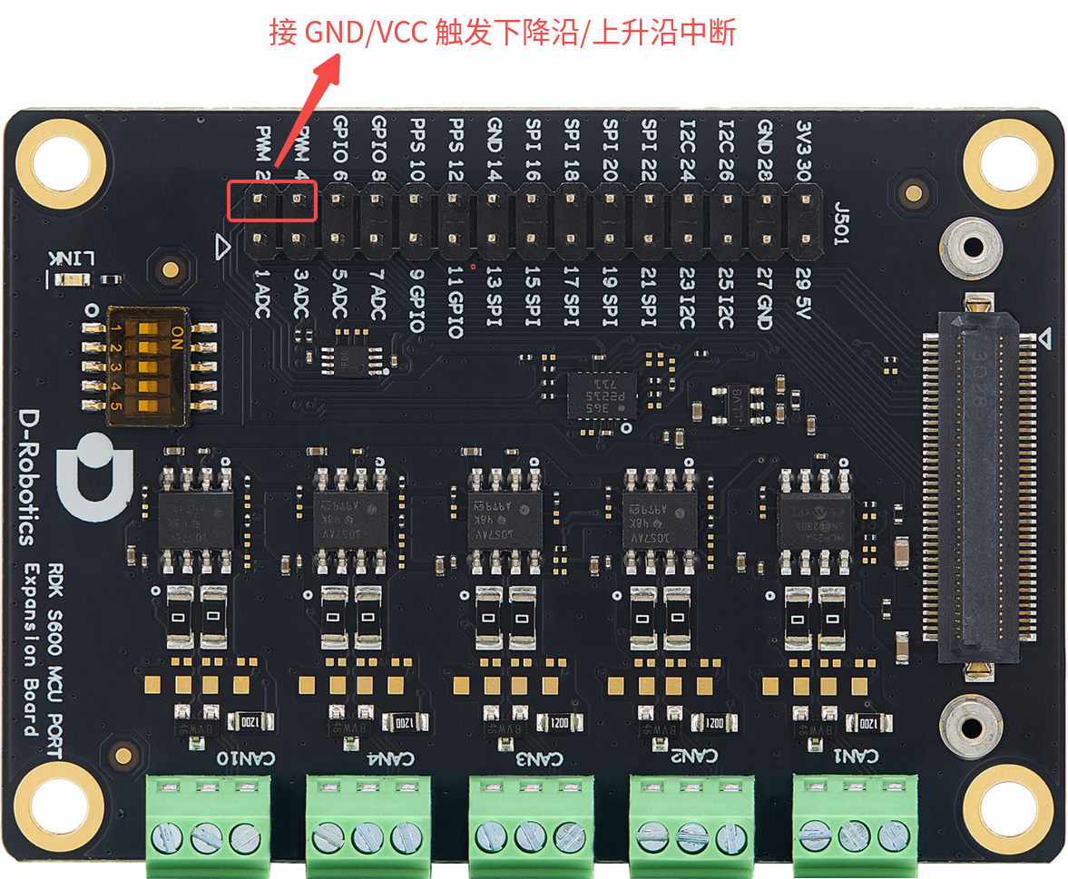
Connect one end of a jumper wire to the two GPIO pins shown below and the other end to ground.
If the serial port prints the following, the GPIO interrupt was triggered successfully:
# GPIO_MCU[52] callback function: 1-instanceNo, 20-PinId
[0667.710363 0]INFO: Enter Icu_Gpio_Channel_1_20_ISR!!!

# GPIO_MCU[53] callback function: 1-instanceNo, 21-PinId
[0593.171002 0]INFO: Enter Icu_Gpio_Channel_1_21_ISR!!!
Disable GPIO interrupts as follows:
D-Robotics:/$ gpio_interrupt off
[0673.558143 0]INFO: Stop gpio_interrupt test