GPIO Interface
Interface Overview
The GPIO (General Purpose Input/Output) interface provides flexible digital I/O expansion. It supports input and output modes and can connect sensors, buttons, indicators, relays, and other external devices. Software can detect device status and control peripherals, giving the system rich hardware interaction for robot control, smart terminals, and embedded applications.
Case Objective
Capture button press events through GPIO.
Required Hardware
- RDK X5 development board
- Female-to-female jumper wires
- GPIO button module
Hardware Connection
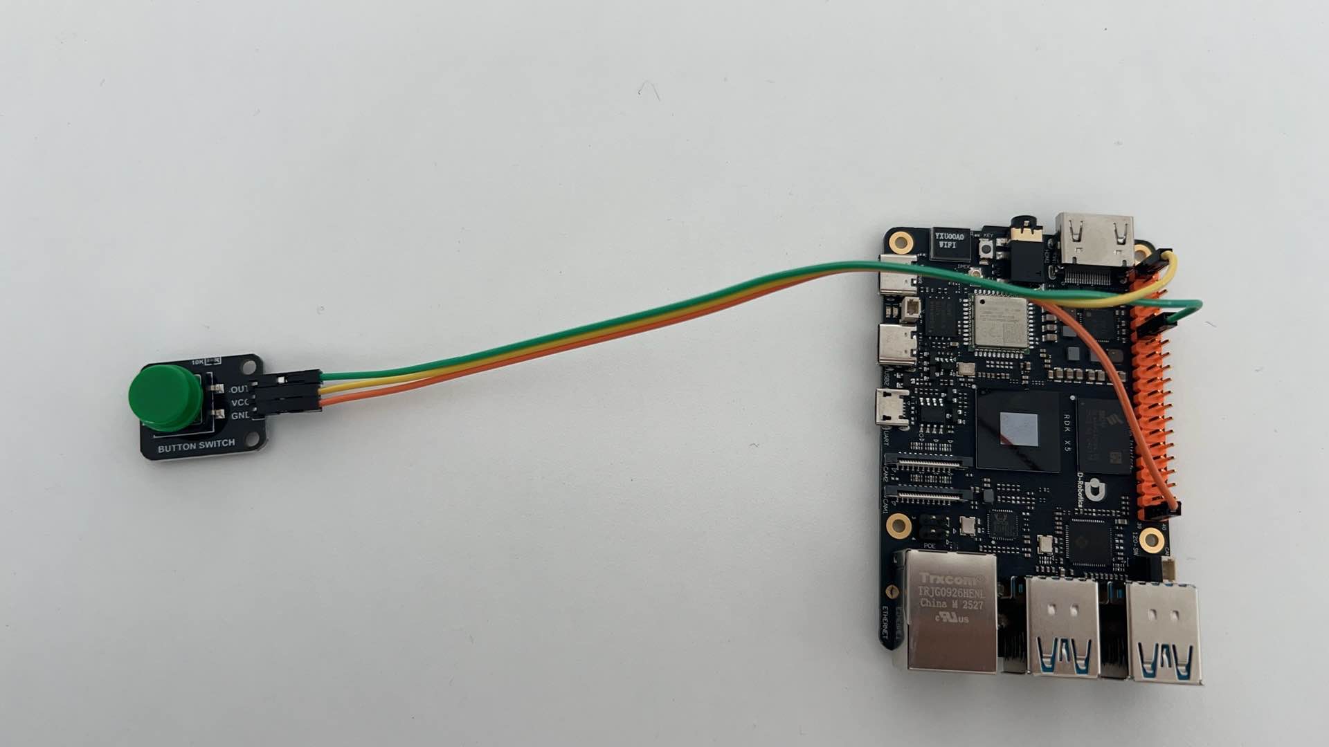
Pin Mapping
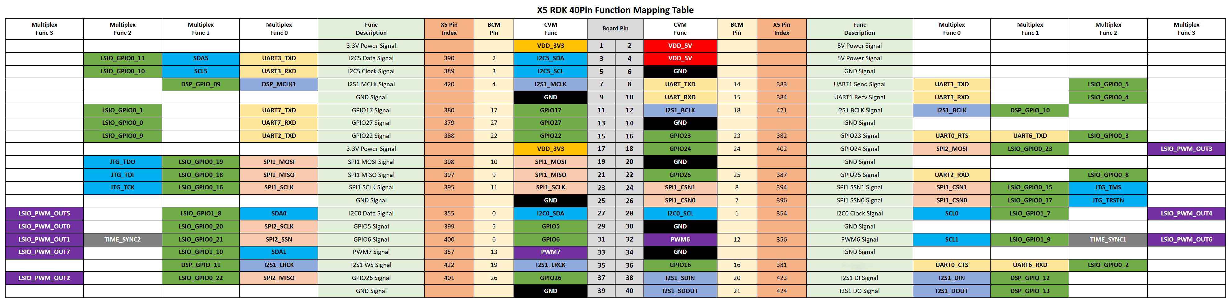
The mapping between button module pins and board pins is shown below. Board pin numbers follow the BOARD numbering in the 40-pin header definition.
| Button module pin | Board pin | Function |
|---|---|---|
| OUT | 11 | Level output |
| VCC | 1 | Power |
| GND | 39 | Ground |
40-Pin Header Definition
Sample Code
Create a gpio_button.py file and paste the following code:
#!/usr/bin/env python3
import sys
import signal
import Hobot.GPIO as GPIO
import time

def signal_handler(signal, frame):
    sys.exit(0)

# 此处使用 11号的 GPIO 引脚
input_pin = 11
GPIO.setwarnings(False)

def main():
    prev_value = None

    # 设置管脚编码模式为硬件编号 BOARD
    GPIO.setmode(GPIO.BOARD)
    # 设置为输入模式
    GPIO.setup(input_pin, GPIO.IN)

    #等待按钮按压事件(GPIO 按钮模块在按压时会输出低电平)
    GPIO.wait_for_edge(input_pin, GPIO.FALLING)
    print("Starting demo now! Press CTRL+C to exit")
    GPIO.cleanup()

if __name__=='__main__':
    signal.signal(signal.SIGINT, signal_handler)
    main()
Run the Sample
Run the sample with the following command:
python3 gpio_button.py
After you press the button, the program prints “Starting demo now! Press CTRL+C to exit”. Press Ctrl+C to exit.
