SPI Debugging Guide
SPI Hardware Support
The S100 Acore supports 2 SPI channels, and SPI0 and SPI1 can only function as SPI Masters.
The S600 Acore supports 4 SPI channels, and all of them can only function as SPI Masters.
On the RDK S600 development board, SPI0 shares 4 pins with CAN0 and CAN1, and the physical traces of these pins are already connected to CAN transceivers; other SPI controllers are not routed out by default on the RDK S600 development board. Therefore, the Acore cannot support external SPI device connections at the hardware level.
Software Architecture
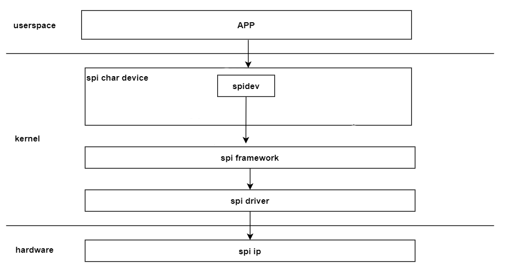
The figure above shows the SPI software architecture. From bottom to top, it can be divided into the hardware IP layer, kernel layer, and user space layer. Each layer is described below.
- Hardware IP Layer: This is the SPI hardware layer.
- Kernel Layer: This can be further divided into 3 sub-layers.
- spi driver layer: Primarily implements operations on the SPI hardware IP and also implements the interfaces defined by the spi framework.
- spi framework layer: Can be understood as the adaptation layer for the spi driver. It defines a set of interfaces that the driver layer needs to implement for the lower layer and provides generic interfaces to the upper layer, hiding hardware details.
- spi char device layer: Provides nodes for user space, facilitating data exchange between user space and kernel space. Currently, the kernel's built-in spidev character device is used.
- App Layer: Consists of various application programs that achieve data exchange with kernel space by calling the character device driver.
Code Paths
Hobot SPI Protocol Code
The hobot SPI driver-related code is located in the $project/hobot-drivers/spi directory.
oops@tiger$ tree . -L 1

├── Kconfig                       # Kconfig related
├── README.md
└──spi_drv                        # spi driver related
$project/hobot-drivers/spi/spi_drv directory description
oops@tiger$ tree . -L 1
├── Makefile
├── spi-dw.c                       # spi driver core code
├── spi-dw.h
├── spi-dw-mmio.c                  # spi driver mmio code
└── spi-dw-mmio-dma.c              # spi driver dma code
Linux SPI Framework Code
The Linux SPI protocol-related code is located in the $project/kernel/drivers/spi directory.
oops@tiger$ tree kernel/drivers/spi/
drivers/spi/
├── spi.c                             # spi framework code

oops@tiger$
SPI Device Tree Code
The dts files related to SPI configuration in the S100 are as follows:
|-- drobot-s100-pinctrl.dtsi       # spi pinctrl related configuration
|-- drobot-s100-soc.dtsi           # spi device node configuration
|-- drobot-s100-pdma.dtsi          # spi pdma usage configuration
The dts files related to SPI configuration in the S600 are as follows:
|-- drobot-s600-pinctrl.dtsi       # spi pinctrl related configuration
|-- drobot-s600-soc.dtsi           # spi device node configuration
|-- drobot-s600-pdma.dtsi          # spi pdma usage configuration
SPI Device Tree Configuration Description
spi0: spi@39800000 {
		compatible = "hobot,hb-dw-spi";
		reg-io-width = <4>;
		#address-cells = <1>;
		#size-cells = <0>;
		reg = <0x0 0x39800000 0x0 0x1000>;
		interrupts = <GIC_SPI PERISYS_SPI0_SSI_INTR PERISYS_SPI0_SSI_INTR_TRIG_TYPE>;
		status = "okay";
		num-cs = <2>;
		resets = <&smc_reset RST_IDX_IP_PERI_SPIM0>,
								<&smc_reset RST_IDX_IP_PERI_SPIM0_APB>;
		reset-names = "spi_reset";
		clocks = <&scmi_smc_clk CLK_IDX_TOP_PERI_SPI_M0>;
		clock-names = "spi_pclk";
		power-domains = <&scmi_smc_pd PD_IDX_LSPERI_TOP>;
		freq-pclk = <200000000>;
		sample-delay = <1>;
		pinctrl-names = "default";
		pinctrl-0 = <&peri_spi0>;
		dmas = <&pdma0 8                        /* read channel */
						&pdma0 9        >;              /* write channel */
		dma-names = "rx", "tx";
		spidev@0 {
				compatible = "rohm,dh2228fv";
				spi-max-frequency = <50000000>;
				reg = <0>;
		};
};

spi1: spi@39810000 {
		compatible = "hobot,hb-dw-spi";
		reg-io-width = <4>;
		#address-cells = <1>;
		#size-cells = <0>;
		reg = <0x0 0x39810000 0x0 0x1000>;
		interrupts = <GIC_SPI PERISYS_SPI1_SSI_INTR PERISYS_SPI1_SSI_INTR_TRIG_TYPE>;
		status = "okay";
		num-cs = <2>;
		resets = <&smc_reset RST_IDX_IP_PERI_SPIM1>,
								<&smc_reset RST_IDX_IP_PERI_SPIM1_APB>;
		reset-names = "spi_reset";
		clocks = <&scmi_smc_clk CLK_IDX_TOP_PERI_SPI_M1>;
		clock-names = "spi_pclk";
		power-domains = <&scmi_smc_pd PD_IDX_LSPERI_TOP>;
		freq-pclk = <200000000>;
		sample-delay = <1>;
		pinctrl-names = "default";
		pinctrl-0 = <&peri_spi1>;
		dmas = <&pdma0 10                       /* read channel */
						&pdma0 11       >;              /* write channel */
		dma-names = "rx", "tx";
		spidev@0 {
				compatible = "rohm,dh2228fv";
				spi-max-frequency = <50000000>;
				reg = <0>;
		};
};
spi0: spi@34900000 {
	compatible = "hobot,hb-dw-spi";
	reg-io-width = <4>;
	#address-cells = <1>;
	#size-cells = <0>;
	reg = <0x0 0x34900000 0x0 0x1000>;
	interrupts = <GIC_SPI  HSISYS_SPI0_SSI_INTR  IRQ_TYPE_LEVEL_HIGH>;
	status = "okay";
	num-cs = <2>;
	//resets = <&smc_reset 0>,
	//			<&smc_reset 0>;
	//reset-names = "spi_reset";
	//clocks = <&scmi_smc_0>;
	//clock-names = "spi_pclk";
	//power-domains = <&scmi_smc_pd 0>;
	freq-pclk = <200000000>;
	sample-delay = <1>;
	pinctrl-names = "default";
	pinctrl-0 = <&hsi_spi0_csn0_spi0_csn0 &hsi_spi0_mosi_spi0_mosi\
			&hsi_spi0_miso_spi0_miso &hsi_spi0_sclk_spi0_sclk>;
	dmas = <&pdma0 16            /* read channel */
				&pdma0 17    >;      /* write channel */
	dma-names = "rx", "tx";
	spidev@0 {
		compatible = "rohm,dh2228fv";
		spi-max-frequency = <50000000>;
		reg = <0>;
	};
};

spi1: spi@34910000 {
	compatible = "hobot,hb-dw-spi";
	reg-io-width = <4>;
	#address-cells = <1>;
	#size-cells = <0>;
	reg = <0x0 0x34910000 0x0 0x1000>;
	interrupts = <GIC_SPI  HSISYS_SPI1_SSI_INTR  IRQ_TYPE_LEVEL_HIGH>;
	status = "okay";
	num-cs = <2>;
	//resets = <&smc_reset 0>,
	//			<&smc_reset 0>;
	//reset-names = "spi_reset";
	//clocks = <&scmi_smc_clk 0>;
	//clock-names = "spi_pclk";
	//power-domains = <&scmi_smc_pd 0>;
	freq-pclk = <200000000>;
	sample-delay = <1>;
	//pinctrl-names = "default";
	//pinctrl-0 = <&hsi_spi1>;
	dmas = <&pdma0 18			/* read channel */
			&pdma0 19	>;		/* write channel */
	dma-names = "rx", "tx";
	spidev@0 {
		compatible = "rohm,dh2228fv";
		spi-max-frequency = <50000000>;
		reg = <0>;
	};
};

spi2: spi@34920000 {
	compatible = "hobot,hb-dw-spi";
	reg-io-width = <4>;
	#address-cells = <1>;
	#size-cells = <0>;
	reg = <0x0 0x34920000 0x0 0x1000>;
	interrupts = <GIC_SPI HSISYS_SPI2_SSI_INTR IRQ_TYPE_LEVEL_HIGH>;
	status = "okay";
	num-cs = <2>;
	//resets = <&smc_reset 0>,
	//			<&smc_reset 0>;
	//reset-names = "spi_reset";
	//clocks = <&scmi_smc_clk 0>;
	//clock-names = "spi_pclk";
	//power-domains = <&scmi_smc_pd 0>;
	freq-pclk = <200000000>;
	sample-delay = <1>;
	//pinctrl-names = "default";
	//pinctrl-0 = <&hsi_spi2>;
	dmas = <&pdma0 20			/* read channel */
			&pdma0 21	>;		/* write channel */
	dma-names = "rx", "tx";
	spidev@0 {
		compatible = "rohm,dh2228fv";
		spi-max-frequency = <50000000>;
		reg = <0>;
	};
};

spi3: spi@34930000 {
	compatible = "hobot,hb-dw-spi";
	reg-io-width = <4>;
	#address-cells = <1>;
	#size-cells = <0>;
	reg = <0x0 0x34930000 0x0 0x1000>;
	interrupts = <GIC_SPI HSISYS_SPI3_SSI_INTR IRQ_TYPE_LEVEL_HIGH>;
	status = "okay";
	num-cs = <2>;
	//resets = <&smc_reset 0>,
	//			<&smc_reset 0>;
	//reset-names = "spi_reset";
	//clocks = <&scmi_smc_clk 0>;
	//clock-names = "spi_pclk";
	//power-domains = <&scmi_smc_pd 0>;
	freq-pclk = <200000000>;
	sample-delay = <1>;
	//pinctrl-names = "default";
	//pinctrl-0 = <&hsi_spi3>;
	dmas = <&pdma0 22			/* read channel */
			&pdma0 23	>;		/* write channel */
	dma-names = "rx", "tx";
	spidev@0 {
		compatible = "rohm,dh2228fv";
		spi-max-frequency = <50000000>;
		reg = <0>;
	};
};
The newly added configuration items for SPI are described here:
- sample-delay: The sampling delay value for received data when the SPI controller acts as a master. If data bit errors occur, this value can be adjusted.
- num-cs: The number of chip selects supported when the SPI controller acts as a master. When acting as a master, a maximum of two chip selects are supported.
SPI Configuration for GPIO CS
Taking spi0 cs1 as an example, add the cs-gpios property to the spi0 node in the device tree to map cs1 to the specified GPIO:
spi0: spi@39800000 {
	...
	pinctrl-0 = <&peri_spi0>;
	cs-gpios = <0>,                                    /* CS0: Natively controlled by SPI controller */
				<&peri_port0 18 GPIO_ACTIVE_LOW>;       /* CS1: Simulated control via GPIO */
	...
};
Note: The GPIO numbers and device tree nodes corresponding to each SPI chip select pin are shown in the table below. You can directly refer to the table to fill in the
cs-gpiosproperty.
| Pin | GPIO | Device Tree |
|---|---|---|
| SPI0_CSN0 | GPIO0[17] | <&peri_port0 17> |
| SPI0_CSN1 | GPIO0[18] | <&peri_port0 18> |
| SPI1_CSN0 | GPIO0[22] | <&peri_port0 22> |
| SPI1_CSN1 | GPIO0[23] | <&peri_port0 23> |
| Pin | GPIO | Device Tree |
|---|---|---|
| SPI0_CSN0 | GPIO1[30] | <&hsi_port1 30> |
| SPI0_CSN1 | GPIO1[31] | <&hsi_port1 31> |
| SPI1_CSN0 | GPIO1[10] | <&hsi_port1 10> |
| SPI1_CSN1 | GPIO1[20] | <&hsi_port1 20> |
| SPI2_CSN0 | GPIO1[16] | <&hsi_port1 16> |
| SPI2_CSN1 | GPIO0[30] | <&hsi_port0 30> |
| SPI3_CSN0 | GPIO1[0] | <&hsi_port1 0> |
| SPI3_CSN1 | GPIO0[31] | <&hsi_port0 31> |
Note: The SPI pin voltage on the S600 is 1.8V. Please ensure voltage level matching with peripheral devices.
Additionally, locate peri_spi0 in source/hobot-drivers/kernel-dts/drobot-xxx-pinctrl.dtsi and remove the cs1-related pins from pinmux and pinconf (to avoid conflicts with the GPIO configuration):
peri_spi0: peri_spi0_func {
	pinmux {
		function = "peri_spi0";
		pins = "peri_spi0_csn0", "peri_spi0_mosi",
				"peri_spi0_miso", "peri_spi0_sclk";
	};
	pinconf {
		pins = "peri_spi0_csn0", "peri_spi0_mosi",
				"peri_spi0_miso", "peri_spi0_sclk";
		drive-strength = <1>;
	};
};
SPI Verification and Debugging
This section mainly introduces how to verify the basic SPI functions of the S100, including environment configuration, execution of test commands, and location of test code.
This section mainly introduces how to verify the basic SPI functions of the S600, including environment configuration, execution of test commands, and location of test code.
Test Environment Preparation
spidev_test is an open-source SPI testing tool. Users can obtain and compile it directly from the following directory in the Linux source code.
Source code location: kernel/tools/spi/spidev_test.c.
Common parameters for spidev_test are described below:
root@ubuntu:/map# ./spidev_test -h
./spidev_test: invalid option -- 'h'
Usage: ./spidev_test [-DsbdlHOLC3vpNR24SI]
   -D --device   device to use (default /dev/spidev1.1)
   -s --speed    max speed (Hz)
   -d --delay    delay (usec)
   -b --bpw      bits per word
   -i --input    input data from a file (e.g. "test.bin")
   -o --output   output data to a file (e.g. "results.bin")
   -l --loop     loopback
   -H --cpha     clock phase
   -O --cpol     clock polarity
   -L --lsb      least significant bit first
   -C --cs-high  chip select active high
   -3 --3wire    SI/SO signals shared
   -v --verbose  Verbose (show tx buffer)
   -p            Send data (e.g. "1234\xde\xad")
   -N --no-cs    no chip select
   -R --ready    slave pulls low to pause
   -2 --dual     dual transfer
   -4 --quad     quad transfer
   -8 --octal    octal transfer
   -S --size     transfer size
   -I --iter     iterations
SPI Internal Loopback Test
The SPI internal loopback test is only supported by SPI Master. Its principle is that the tx fifo of the SPI hardware IP sends data to the rx fifo, thus forming a loopback.
Test command and results reference are as follows:
root@ubuntu:/map# ./spidev_test -D /dev/spidev1.0 -s 1000000 -S 100 -l -v -p "\x01\x02\x03\x04"
spi mode: 0x20
bits per word: 8
max speed: 1000000 Hz (1000 kHz)
TX | 01 02 03 04 __ __ __ __ __ __ __ __ __ __ __ __ __ __ __ __ __ __ __ __ __ __ __ __ __ __ __ __  |....|
RX | 01 02 03 04 __ __ __ __ __ __ __ __ __ __ __ __ __ __ __ __ __ __ __ __ __ __ __ __ __ __ __ __  |....|
SPI External Loopback Test
The SPI external loopback test refers to an SPI Master connected to an SPI Slave.
For the Master, you can choose SPI1, and for the SPI Slave, choose an external SPI device (selected by the customer).
The test command reference for the S100 side is as follows:
root@ubuntu:/map# ./spidev_test -D /dev/spidev1.0 -s 1000000 -S 100  -v -p "\x01\x02\x03\x04"
spi mode: 0x0
bits per word: 8
max speed: 1000000 Hz (1000 kHz)
TX | 01 02 03 04 __ __ __ __ __ __ __ __ __ __ __ __ __ __ __ __ __ __ __ __ __ __ __ __ __ __ __ __  |....|
RX | FF FF FF FF __ __ __ __ __ __ __ __ __ __ __ __ __ __ __ __ __ __ __ __ __ __ __ __ __ __ __ __  |....|
On the Slave device side, the data sent by the S100 Master will be received.
Note: When performing an external loopback test, the SPI Slave program must be executed first, followed by the SPI Master program. If the SPI Master program is executed first and then the SPI Slave program, data loss during SPI reception may occur due to master-slave synchronization issues.
This test is not currently supported.