4.1.1.6. Model Quantization and Compilation
The conversion of the floating-point model to the D-Robotics Hybrid Heterogeneous Model will be completed in the Convert Model phase, after which you will get a model that can run on the D-Robotics computing platform. Before performing the conversion, make sure you have successfully passed the model check as described in the Check the Model section.
The model conversion is executed by the hb_mapper makertbin tool. During the conversion, some important procedures such as model optimization and calibration quantization must prepare the data in line with model pre-processing requirements.
You can refer to Prepare Calibration Data section to prepare the calibration data in advance.
To give you a comprehensive understanding of model conversion, this section introduces the use of conversion tools, conversion internal procedure, conversion results parsing, and conversion output chronologically.
4.1.1.6.1. Convert the Model Using the hb_mapper makertbin Tool
The hb_mapper makertbin provides two modes, with fast-perf mode on and without fast-perf mode on.
The fast-perf mode, when turned on, will generate the bin model that can have the highest performance when running on the board side during the conversion process,
and the tool internally performs the following operations:
Run BPU executable operators on the BPU whenever possible (i.e. you can specify the operators to run on the BPU via the node_info parameter in the yaml file).
Remove CPU operators that are removable at the beginning and end of the model, including: Quantize/Dequantize, Transpose, Cast, Reshape, etc.
Compile the model with the O3 optimization level(which has the highest performance).
How to use hb_mapper makertbin command:
The fast-perf mode is not turned on:
hb_mapper makertbin --config ${config_file}  \
                    --model-type  ${model_type}
The fast-perf mode is turned on:
hb_mapper makertbin --fast-perf --model ${caffe_model/onnx_model} --model-type ${model_type} \
                    --proto ${caffe_proto} \
                    --march ${march} \
                    --input-shape ${input_node_name} ${input_shape}
- Parameters:
- --help
Shows help information and exit.
- -c, --config
Configuration file for the model compilation, in YAML format.
- --model-type
caffeoronnx.- --fast-perf
Turn on fast-perf mode, this mode will generate the bin model that can have the highest performance when running on the board side during the conversion process, so that you can easily use it for the model performance evaluation later.
If you turned on fast-perf mode, you also need to configure the following:
--modelFloating-point model file of Caffe/ONNX.--protoSpecify the Prototxt file of the Caffe model.--marchBPU’s micro architecture. For X3 series processors, set tobernoulli2(default).-i, --input-shapeOptional parameter that specifies the shape of the input node of the model. Currently, this configuration only takes effect when fast-perf is turned on. It is used in the following way:Specify the shape information of a single input node, example of how to use:
--input-shape input_1 1x3x224x224.Specify the shapes of multiple input nodes, example of how to use:
--input-shape input_1 1x3x224x224 --input-shape input_2 1x3x224x224.
Attention
If you do not specify the
--input-shape, the tool will only support the model with the first dimension of the dynamic input node [-1, 0, ?] and the first dimension of the dynamic input node will be set to 1 by default.
4.1.1.6.1.1. Configuration File Template
A complete configuration file template is shown as below:
Note
Below configuration file is only for display, in an actual configuration file of a model,
the caffe_model and onnx_model parameters are not coexisting.
The model should be either a Caffe or an ONNX model.
That is, caffe_model + prototxt or onnx_model , you need to choose one of the two when configuring.
# model parameters
model_parameters:
  # The descriptive file of the original Caffe floating-point model
  prototxt: '***.prototxt'

  # The original Caffe model file
  caffe_model: '****.caffemodel'

  # The original ONNX model file
  onnx_model: '****.onnx'

  # The target processor architecture of conversion
  march: 'bernoulli2'

  # The prefix of the converted model file which will run on the dev board
  output_model_file_prefix: 'mobilenetv1'

  # The directory where the conversion results will be saved
  working_dir: './model_output_dir'

  # To specify whether the converted Hybrid heterogeneous model retains the ability to output the intermediate layer results for each layer after conversion
  layer_out_dump: False

  # Specify the output node of the model
  output_nodes: "OP_name"

  # Batch delete nodes of a certain type
  remove_node_type: Dequantize

  # Delete the node with the specified name
  remove_node_name: "OP_name"

# input information parameters
input_parameters:
  # The input node name of the floating-point model
  input_name: "data"

  # The input data format of the original floating-point model (quantity/sequence consistent with the input_name)
  input_type_train: 'bgr'

  # The input data layout of the original floating-point model (quantity/sequence consistent with the input_name)
  input_layout_train: 'NCHW'

  # The input data size of the original floating-point model
  input_shape: '1x3x224x224'

  # The data batch_size input to the neural network when the network is actually executed
  input_batch: 1

  # The data pre-processing method to be added into the model
  norm_type: 'data_mean_and_scale'

  # The mean value of the image subtracted by the preprocessing method, if it is the channel mean, the values must be separated by a space
  mean_value: '103.94 116.78 123.68'

  # The image scaling of the preprocessing method, if it is a channel scaling, the values must be separated by a space
  scale_value: '0.017'

  # The input data format which the converted heterogeneous model needs to match
  # (quantity/sequence consistent with the input_name)
  input_type_rt: 'yuv444'

  # Special input data format
  input_space_and_range: 'regular'

  # The input data layout which the converted heterogeneous model needs to match
  # (quantity/sequence consistent with the input_name)
  # If input_type_rt is configured as nv12, then This parameter does not need to be configured
  input_layout_rt: 'NHWC'

# Calibration parameters
calibration_parameters:
  # The directory where the calibration samples will be saved
  cal_data_dir: './calibration_data'

  # Specify the data storage type of the calibration data binary file.
  cal_data_type: 'float32'

  # Turn on/off automatic image calibration sample processing (skimage read; resize to the input node size)
  #preprocess_on: False

  # Type of algorithms used for calibration
  calibration_type: 'kl'

  # max calibration parameter
  max_percentile: 1.0

  # Force an OP to run on the CPU
  run_on_cpu: "OP_name"

  # Force an OP to run on the BPU
  run_on_bpu: "OP_name"

  # Specify whether to calibrate for each channel
  per_channel: False

  # Specify the data precision of the output node
  optimization: set_model_output_int8

# compilation parameters
compiler_parameters:
  # Select compilation strategy
  compile_mode: 'latency'

  # Turn on/off the debug information for compilation
  debug: True

  # Number of cores to run the model
  core_num: 1

  # Select the priority of model compilation
  optimize_level: 'O2'

  # Specify the input data source with the name data
  input_source: {"data": "pyramid"}

  # Specify the maximum continuous execution time for each function call of the model
  max_time_per_fc: 1000

  # Specify the number of processes when compiling the model
  jobs: 8

# custom op parameters
custom_op:
  # The calibration method of the customized OP
  custom_op_method: register

  # The implementation file of the customized OP
  # This file can be generated from templates. Please refer to the customized OP related docs for details
  op_register_files: sample_custom.py

  # The folder in which the customized OP implementation file resides, please use the relative path
  custom_op_dir: ./custom_op
The parameters in the configuration file is composed by: model parameters, input information parameters, calibration parameters, compilation parameters and custom op parameters. All parameter sets must exist in your configuration file. Parameters can be divided into the required and the optional, while you can leave the optional parameters unconfigured.
The following is the specific parameter information, the parameters will be more, we follow the above parameter group order to introduce. Required/Optional indicates whether this parameter must be specified in the Yaml file.
4.1.1.6.1.2. Specific Parameter Information
🛠️ Model Parameters
NO. |
PARAMETER |
DESCRIPTIONS |
Required/Optional |
|---|---|---|---|
1 |
|
PURPOSE: This parameter specifies the prototxt filename of the floating-point Caffe model. RANGE: None. DEFAULT VALUE: None. DESCRIPTIONS: This parameter must be specified when the |
optional |
2 |
|
PURPOSE: This parameter specifies the caffemodel filename of the floating-point Caffe model. RANGE: None. DEFAULT VALUE: None. DESCRIPTIONS: This parameter must be specified when the |
optional |
3 |
|
PURPOSE: This parameter specifies the onnx filename of the floating-point ONNX model. RANGE: None. DEFAULT VALUE: None. DESCRIPTIONS: This parameter must be specified when the |
optional |
4 |
|
PURPOSE: This parameter specifies the platform architecture to run the converted heterogeneous model. RANGE: DEFAULT VALUE: None. DESCRIPTIONS: For X3 processors, use Depending on the platform you are using, you can choose between the two options. |
required |
5 |
|
PURPOSE: This parameter specifies the prefix of the converted heterogeneous model filename. RANGE: None. DEFAULT VALUE: DESCRIPTIONS: This parameter specifies the prefix of the converted heterogeneous model filename. |
optional |
6 |
|
PURPOSE: This parameter specifies the directory to save the conversion results. RANGE: None. DEFAULT VALUE: DESCRIPTIONS: The tool will create a new directory automatically if it doesn’t exist. |
optional |
7 |
|
PURPOSE: This parameter specifies whether the heterogeneous model retains the ability to output intermediate layer values. RANGE: DEFAULT VALUE: DESCRIPTIONS: Dumping the intermediate layer results is a debugging method, please do not enable it unless it is necessary. Attention: It is not supported to configure input_source to be resizer when layer_out_dump is True. |
optional |
8 |
|
PURPOSE: This parameter specifies model output node(s). RANGE: None. DEFAULT VALUE: None. DESCRIPTIONS: This parameter is used to support you to specify the node as the model output, the value should be the specific node name of the model. When there are multiple values, please refer to param_value Configuration. |
optional |
9 |
|
PURPOSE: This parameter sets the type of the deleted node. RANGE: “Quantize”, “Transpose”,”Dequantize”, “Cast”, “Reshape” and “Softmax”. Different types should be split by “;”. DEFAULT VALUE: None. DESCRIPTIONS: No settings or set to null doesn’t affect the model conversion process. This parameter is used to support you in settinf the type information of the node to be deleted. The deleted node must be at the beginning or end of the model, connected to the input or output of the model. Attention: The to-be-deleted node will be deleted sequentially and the model structure is dynamically updated. It also determines whether the node is located at the input and output of the model before the node is deleted. So the order of node deletion is important. |
optional |
10 |
|
PURPOSE: This parameter sets the name of the deleted node. RANGE: None. Different names should be split by “;”. DEFAULT VALUE: None. DESCRIPTIONS: No settings or set to null doesn’t affect the model conversion process. This parameter is used to support you in setting the name of the node to be deleted. The deleted node must be at the beginning or the end of the model, connected to the input or output of the model. Attention: The to-be-deleted node will be deleted sequentially and the model structure is dynamically updated. It also determines whether the node is located at the input and output of the model before the node is deleted. So the order of node deletion is important. |
optional |
11 |
|
PURPOSE: Save calibration data for accuracy debug analysis. RANGE: DEFAULT VALUE: None. DESCRIPTIONS: This parameter serves to save the calibration data for the accuracy debug analysis and the data format is .npy. This data can be fed directly into the model for inference via np.load(). If you don’t set this parameter, you can also save the data yourself and use the accuracy debug tool for accuracy analysis. |
optional |
🛠️ Input Information Parameters
NO. |
PARAMETER |
DESCRIPTIONS |
Required/Optional |
|---|---|---|---|
1 |
|
PURPOSE: This parameter specifies the input node names of the original floating-point model. RANGE: None. DEFAULT VALUE: None. DESCRIPTIONS: No configuration is required if there is only one input node. If there are more than one nodes, it must be configured so as to guarantee the accuracy of subsequent types and input sequence of the calibration data. For configuration methods of multiple values, please refer to param_value Configuration. |
optional |
2 |
|
PURPOSE: This parameter specifies the input data type of the original floating-point model. RANGE: DEFAULT VALUE: None. DESCRIPTIONS: Each input node needs to be configured with a defined input data type. If there are multiple input nodes,
the order of the nodes must be strictly consistent with the order in the For configuration methods of multiple values, please refer to param_value Configuration. For the selection of data types, please refer to: Model Conversion Interpretation section. |
required |
3 |
|
PURPOSE: This parameter specifies the input data layout of the original floating-point model. RANGE: DEFAULT VALUE: None. DESCRIPTIONS: Each input node needs to be configured with a defined input data layout that shall be the same as the layout of the original floating-point model. If there are multiple input nodes, the order of the nodes must be strictly consistent with the For configuration methods of multiple values, please refer to param_value Configuration. For more about data layout, please refer to Model Conversion Interpretation section. |
required |
4 |
|
PURPOSE: This parameter specifies the input data format that the converted heterogeneous model must match. RANGE: DEFAULT VALUE: None. DESCRIPTIONS: Here is an indication of the data format you need to use It doesn’t have to be the same as the data format of the original model, but note that this is the format that will actually feed into your model when running on the computing platformr. Each input node needs to be configured with a defined input data layout. If there are multiple input nodes,
the sequence of the configured nodes must be strictly consistent with the For configuration methods of multiple values, please refer to param_value Configuration. For the selection of data types, please refer to Model Conversion Interpretation section. |
required |
5 |
|
PURPOSE: This parameter specifies the input data layout that the converted heterogeneous model must match. RANGE: DEFAULT VALUE: None. DESCRIPTIONS: Each input node needs to be configured a defined input data layout and this input is the layout you wish to specify for the hybrid heterogeneous model. Unsuitable input data layout settings will affect performance. If there are multiple input nodes, the order of the nodes must be strictly consistent with the order in For configuration methods of multiple values please refer to param_value Configuration. For more about data layout, please refer to Model Conversion Interpretation section. |
optional |
6 |
|
PURPOSE: This parameter specifies special data formats. RANGE: DEFAULT VALUE: DESCRIPTIONS: The purpose of this parameter is to deal with the YUV420 format dumped by different ISP and it will
only become valid when the
Attention: You don’t need to configure this parameter without explicit requirements. |
optional |
7 |
|
PURPOSE: This parameter specifies the input data size of the original floating-point model. RANGE: None. DEFAULT VALUE: None. DESCRIPTIONS: Dimensions of shape should be separated by You don’t need to configure this parameter unless there are more input nodes in the model, because the tool can read the size information from model files automatically. When there are multiple input nodes, the sequence of configured nodes must be strictly consistent with the For configuration methods of multiple values, please refer to param_value Configuration. |
optional |
8 |
|
PURPOSE: This parameter specifies the input data batch size that the converted heterogeneous model must match. RANGE: DEFAULT VALUE: DESCRIPTIONS: This parameter specifies the input data batch size that the converted heterogeneous model must match, but does not affect the input data batch size of the converted onnx model. This parameter only supports specifying a single value, which will act on all inputs of the model when the model has multiple inputs. If you don’t configure this parameter, the default value is 1. Attention:
|
optional |
9 |
|
PURPOSE: This parameter specifies the pre-processing method to deal with the model input data. RANGE: DEFAULT VALUE: DESCRIPTIONS:
When there are multiple input nodes, the sequence of configured nodes must be strictly consistent with the For configuration methods of multiple values, please refer to param_value Configuration. For the influence of this parameter, please refer to Model Conversion Interpretation section. Attention:
When |
optional |
10 |
|
PURPOSE: This parameter specifies the mean value to be subtracted by the pre-processing method. RANGE: None. DEFAULT VALUE: None. DESCRIPTIONS: This parameter will be valid when the Each input node has 2 configuration methods. If only one value is specified, then all channels will subtract the same mean value. Otherwise, you need to specify the mean values for each channel and the number of values (separated by space) must be consistent with the numbers of channel. The number of configured input nodes must be consistent with the node number specified by If there is a node that doesn’t require For configuration methods of multiple values, please refer to param_value Configuration. |
optional |
11 |
|
PURPOSE: This parameter specifies the scale factor of the pre-processing method. RANGE: None. DEFAULT VALUE: None. DESCRIPTIONS: This parameter will be valid when the You can either specify only 1 value for all channels or specify the values (separated by space) for each channel. The number of values must be consistent with number of channels. The number of configured input nodes must be consistent with the node number specified by If there is a node that doesn’t require For configuration methods of multiple values, please refer to param_value Configuration. |
optional |
🛠️ Calibration Parameters
NO. |
PARAMETER |
DESCRIPTIONS |
Required/Optional |
|---|---|---|---|
1 |
|
PURPOSE: This parameter specifies the directory to save the calibration samples. RANGE: None. DEFAULT VALUE: None. DESCRIPTIONS: The calibration data in the directory must comply with the requirements of input configurations, please refer to the Prepare Calibration Data section. When there are multiple input nodes, the sequence of configured nodes must be strictly consistent with the For configuration methods of multiple values, please refer to param_value Configuration. When calibration_type is Attention:
For your convenience, if the cal_data_type configuration is not found, we will configure the data type according to the folder suffix.
If the folder suffix ends with |
calibration_type specified as non-skip: required |
2 |
|
PURPOSE: This parameter specifies the data storage type of the calibration data binary file. RANGE: DEFAULT VALUE: None. DESCRIPTIONS: It specifies the data storage type of the binary file used for model calibration. If no value is specified, the folder name suffix will be used to make the determination. For configuration methods of multiple values, please refer to param_value Configuration. |
optional |
3 |
|
PURPOSE: This parameter enables automatic processing of image calibration samples. RANGE: DEFAULT VALUE: DESCRIPTIONS: This option is only available for models with 4-dimensional image input. Do not enable this option for non-4D models. When this function is enabled, there are , etc. image data saved in the To ensure that the calibration is effective, it is recommended to keep this parameter disabled. For the influence of this parameter, please refer to the Prepare Calibration Data section. |
optional |
4 |
|
PURPOSE: This parameter specifies the types of algorithms used in the calibration. RANGE: DEFAULT VALUE: DESCRIPTIONS: Both the When using the For details, see Further Improve Model Accuracy Using The QAT Solution .
If you are using a QAT exported model, you should select It is recommended to firstly try the If you only want to try to verify the model performance, but do not require the accuracy, you can try the Attention: When using the skip, the model obtained cannot be used for accuracy verification because it uses max + internally generated random calibration data for calibration. |
optional |
5 |
|
PURPOSE: This is the parameter of the RANGE: DEFAULT VALUE: DESCRIPTIONS: This parameter is valid only when the Typical options: 0.99999/0.99995/0.99990/0.99950/0.99900. It is recommended to firstly specify the |
optional |
6 |
|
PURPOSE: This parameter determines whether to calibrate each channel of featuremap. RANGE: DEFAULT VALUE: DESCRIPTIONS: This parameter is valid only when the You are recommended to firstly try the |
optional |
7 |
|
PURPOSE: This parameter forces the specified operator to run on the CPU. RANGE: None. DEFAULT VALUE: None. DESCRIPTIONS: The performance on CPU is not as good as BPU, but it provides floating-point accuracy computing capacity. So you can specify this parameter to force some OPs to run on the CPU. For configuration methods of multiple values, please refer to param_value Configuration. |
optional |
8 |
|
PURPOSE: This parameter forces OPs to run on the BPU. RANGE: None. DEFAULT VALUE: None. DESCRIPTIONS: To ensure the accuracy of the final quantized model, in rare cases, the conversion tool will run some BPU qualified OPs on the CPU. If you have higher performance requirements and are willing to pay for some quantization loss, please specify this parameter to force some OPs to run on the BPU. Setting the value to the specific node name in the model. For configuration methods of multiple values, please refer to param_value Configuration. |
optional |
9 |
|
PURPOSE: This parameter makes the model output in int8 format. RANGE: DEFAULT VALUE: None. DESCRIPTIONS: When the value is specified as set_model_output_int8, set the model to output in int8 format with low accuracy. |
optional |
🛠️ Compilation Parameters
NO. |
PARAMETER |
DESCRIPTIONS |
Required/Optional |
|---|---|---|---|
1 |
|
PURPOSE: This parameter specifies compilation strategies. RANGE: DEFAULT VALUE: DESCRIPTIONS: The The The It is recommended to use the |
optional |
2 |
|
PURPOSE: This parameter specifies the balance ratio when the compile_mode is specified as balance. RANGE: DEFAULT VALUE: None. DESCRIPTIONS: This parameter is only used when the compile_mode is specified as balance, otherwise the configuration will not take effect.
|
compile_mode specified as balance: required |
3 |
|
PURPOSE: This parameter determines whether to enable debugging information. RANGE: DEFAULT VALUE: DESCRIPTIONS: In scenarios where this parameter is turned on by default, the performance results of the static analysis of the model will be saved in the model. You can view the performance information of the model’s layer-by-layer BPU operators, including computation amount, original op output shape, aligned op output shape, computation time, data handling time and the active time period of the compiled layer (does not represent the execution time of the layer, usually multiple layers alternate/execute in parallel) of each layer of BPU operators in the Layer Details tab within the html page of the static performance evaluation file generated after the model is successfully converted and the html page generated during hb_perf. |
optional |
4 |
|
PURPOSE: This parameter specifies the number of cores to run model. RANGE: DEFAULT VALUE: DESCRIPTIONS: The D-Robotics platform supports simultaneous completion of an inference task using multiple accelerator cores. Multiple cores are suitable for larger input sizes. Ideally, the dual-core inference speed can reach 1.5x faster than the single-core. If the model has a large input size and you require higher speed, try |
optional |
5 |
|
PURPOSE: This parameter specifies the model optimization levels. RANGE: DEFAULT VALUE: DESCRIPTIONS: Optimization level ranges between
For models that are normally used for production and validation performance, the |
optional |
6 |
|
PURPOSE: This parameter specifies the input source of dev board bin models. RANGE: DEFAULT VALUE: None, it will be automatically selected from an optional range based on the value of input_type_rt by default.
DESCRIPTIONS: This is an option for adapting the engineering environment and you are recommended to configure it after all model validations are complete. The To configure the This parameter is a bit special, e.g., if the model input name is data and the data source is memory (ddr), then this parameter should be
configured as |
optional |
7 |
|
PURPOSE: This parameter specifies the maximum continuous execution time (by μs) of model’s each function call. RANGE: DEFAULT VALUE: DESCRIPTIONS: The inference of the compiled directive model in the BPU are denoted by 1 or multiple function-calls(the function-call is the atomic unit in BPU execution). The value of 0 means no restriction. This parameter is used for specifying the max execution time of each function-call. The model only has a chance to be preempted when the execution of a single function-call is finished. Please refer to the Model Preemption Control section. Attention:
|
optional |
8 |
|
PURPOSE: This parameter sets the number of processes when compiling the bin model. RANGE: DEFAULT VALUE: None. DESCRIPTIONS: When you compile the bin model, it is used to set the number of processes. It can improve the compilation speed to some extent. |
optional |
9 |
|
PURPOSE: This parameter is used to indicate the predicted increase in elapsed time in microseconds after the model is compiled. RANGE: Natural number. DEFAULT VALUE: Not set or set to 0 means not enabled. DESCRIPTIONS: During the model compilation process, the toolchain will perform a time consumption analysis internally. In the actual process, the time consumption will be increased when doing operations such as data alignment of operators. After setting this parameter, when the deviation between the actual computation time and the theoretical computation time of a certain OP is larger than the value you specify, the relevant log will be printed, including information about the change in time, the shape and padding ratio before and after data alignment, etc. |
optional |
🛠️ Custom OP Parameters
NO. |
PARAMETER |
DESCRIPTIONS |
Required/Optional |
|---|---|---|---|
1 |
|
PURPOSE: This parameter specifies customized OP strategy. RANGE: DEFAULT VALUE: None. DESCRIPTIONS: Currently, only the register strategy is supported. For details, please refer to the Custom OP Development. |
optional |
2 |
|
PURPOSE: This parameter specifies customized OP’s Python implementation filename. RANGE: None. DEFAULT VALUE: None. DESCRIPTIONS: Multiple files can be separated by For details, please refer to the Custom OP Development. |
optional |
3 |
|
PURPOSE: This parameter specifies the path of customized OP’s Python implementation file. RANGE: None. DEFAULT VALUE: None. DESCRIPTIONS: If the customized OP’s Python implementation is in the same directory as the working directory, it can be unset. Please use relative path when specifying this parameter. |
optional |
4.1.1.6.1.3. param_value Configuration
You can specify the parameters like this: param_name: 'param_value',
while multiple values can be separated by ';':
param_name: 'param_value1; param_value2; param_value3'.
Tip
To avoid parameter sequence problems, You are strongly suggested to specify the parameters(such as input_shape etc.)
explicitly when there are multi-input models.
Attention
If
input_type_rtis set tonv12oryuv444, no odd numbers can appear in the input size of the model.Please note that the scenario where
input_type_rtisyuv444andinput_layout_rtisNCHWis not supported on X3 at the moment.
4.1.1.6.2. Model Conversion Interpretation
Model conversion is completed from a floating-point model to a hybrid heterogeneous model supported by D-Robotics’ computing platform. To make this heterogeneous model run quickly and efficiently on the embedded end, the model conversion focuses on solving two problems, input data processing and model optimization compilation, and this section will focus on these two problems in turn.
In terms of Input data processing, D-Robotics’ edge computing platform can provide hardware-level solutions for specific types of input channels, but the output of these solutions may not comply with the input requirements of your models. For example, the video processing sub-systems for video channels have the abilities to crop and scale images or optimize the image quality. The output of these sub-systems are mostly in the YUV420 format, however, the algorithm models are often trained based on commonly-used image formats such as bgr/rgb.
To solve this problem, D-Robotics provides 2 kinds of input descriptions for each converted model:
The one is used for the original floating-point model input (input_type_train and input_layout_train); while the other one is used for the input data (input_type_rt and input_layout_rt) of the edge platform that you are going to use.
For the frequently-used image data pre-processing, such as mean and scale, the edge platform data formats such as yuv420 are no longer suitable for such operations, therefore, we integrate these common image pre-processing into the model. After the above two processes, the input part of the converted heterogeneous model will be shown as follows

There are only 2 types of data layouts in the above diagram: NCHW and NHWC.
Wherein, N denotes quantity, C denotes channel, H denotes height and W denotes width.
The two different layouts reflect different memory access characteristics.
The NHWC layout are more often used by the TensorFlow models; while the NCHW layout is used by the Caffe models.
Although D-Robotics’ edge platform doesn’t restrict the data layout, there are still 2 requirements:
Firstly, the input_layout_train must be consistent with the data layout of the original floating-point model;
Secondly, the data must be prepared in the edge platform with a consistent data layout with input_layout_rt, as specifying correct data layout is the basis for smooth data parsing.
The tool will automatically add data conversion nodes according to the data formats specified by the input_type_rt and input_type_train. Not any type combination is needed, in order to avoid your misuse, we only open some fixed type combinations in the following table:
input_type_train \ input_type_rt |
nv12 |
yuv444 |
rgb |
bgr |
gray |
featuremap |
|---|---|---|---|---|---|---|
yuv444 |
Y |
Y |
N |
N |
N |
N |
rgb |
Y |
Y |
Y |
Y |
N |
N |
bgr |
Y |
Y |
Y |
Y |
N |
N |
gray |
N |
N |
N |
N |
Y |
N |
featuremap |
N |
N |
N |
N |
N |
Y |
Note
The first row of the table is the data types supported in input_type_rt and the first column is the data types supported in input_type_train.
The Y/N indicates whether to support the conversion between input_type_rt and input_type_train.
In the final bin model obtained from the conversion, the conversion from input_type_rt to input_type_train is an internal process.
You only need to focus on the data format of input_type_rt. It is of vital importance to understand
the requirement of the input_type_rt when preparing the inference data for embedded applications,
please refer to the following explanations to each format of the input_type_rt.
rgb, bgr, and gray are commonly used image format. Note that each value is represented using UINT8.
yuv444 is a popular image format. Note that each value is represented using UINT8.
NV12 is a popular YUV420 image format. note that each value is represented using UINT8.
One special case of NV12 is to specify the
bt601_videoof theinput_space_and_range. Compared with typical NV12 format, its value range has changed from [0,255] to [16,235]. Each value is still represented as UINT8. Note thatbt601_videois supported configuring viainput_space_and_rangeonly wheninput_type_trainisbgrorrgb.Featuremap is suitable for cases where the above listed formats failed to meet your needs, and this type uses float32 for each value. For example, this format is commonly used for model processing such as radar and speech.
Tip
The above input_type_rt and input_type_train are integrated into the toolchain processing procedure. If you are very sure that no format conversion is required, then set the two input_type to be the same, so that the same input_type will perform the processing in a straight-through way and will not affect the actual execution performance of the model.
Similarly, data pre-processing also is also integrated into the process. If you don’t need to do any pre-processing, you can disable this function through the norm_type configuration, which will not affect the actual execution performance of the model.
Model Optimization and Compilation: It completes several important steps, including model parsing, model optimization, model calibration and quantification, and model compilation, and its internal working process is shown in the figure below.
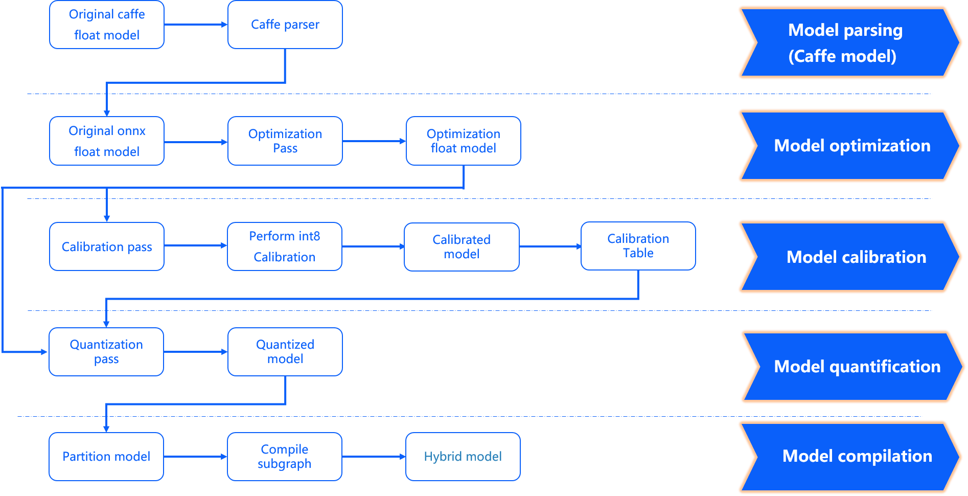
model parse stage: It completes the conversion from Caffe floating-point model to ONNX floating-point model and determines whether to add a data pre-processing node to the original floating-point model according to the configuration parameters. An original_float_model.onnx will be produced at this stage. This ONNX model is still computed with float32 precision, and a data pre-processing node is added into the input.
Ideally, this pre-processing node should complete the conversion from input_type_rt to input_type_train.
Actually, the conversion of model types also relies on the D-Robotics processor hardware, but the ONNX model doesn’t include the hardware conversion, so the actual ONNX input uses an intermediate format which matches the processing results of the input_type_rt.
The data layout (NCHW/NHWC) will keep the input layout of the original floating-point model consistent.
Each type of input_type_rt has a specific corresponding intermediate type, as follows:
nv12 |
yuv444 |
rgb |
bgr |
gray |
featuremap |
|---|---|---|---|---|---|
yuv444_128 |
yuv444_128 |
RGB_128 |
BGR_128 |
GRAY_128 |
featuremap |
Note
The bolded characters in the first row of the table is the data type specified by input_type_rt, and the second row is the intermediate type corresponding to the specific input_type_rt.
This intermediate type is the input type of original_float_model.onnx. Among them:
*_128 is the result of subtracting 128 from its data type. Each value is represented by int8.
Featuremap is tensor data and each value is represented by float32.
Model Optimization Stage: It implements some operator optimization strategies for the model that are applicable to the D-Robotics platform, such as BN fusion to Conv, etc. The output of this phase is an optimized_float_model.onnx. The computational accuracy of this ONNX model is still float32, which will not affect the computational results of the model after optimization. The input data requirements of the model are still the same as the previous original_float_model.
Model Calibration Stage: It uses the calibration data you provide to calculate the necessary quantization parameters, and the quantization parameters corresponding to each node calculated from the calibration data will be saved in the calibration node. The output of this phase is a calibrated_model.onnx.
Model Quantization Stage: The model quantization is completed using the parameters obtained from the calibration.
The output of this phase is a quantized_model.onnx. The computational accuracy of this model is already int8, and the loss of accuracy due to model quantization can be evaluated using this model.
The model requires the same basic data format and layout as original_float_model, but the range of values has changed. The overall change in the input compared to original_float_model is described as follows:
The data layouts all use NHWC.
When
input_type_rttakes a value other thanfeaturemap, the input data types are all INT8, and conversely, wheninput_type_rttakes a value offeaturemap, the input data type is float32.
The layout relationship corresponds to the following example:
Original model input layout: NCHW.
input_layout_train: NCHW.
origin.onnx input layout: NCHW.
calibrated_model.onnx input layout: NCHW.
quanti.onnx input_layout: NHWC.
That is, the input_layout_train, origin.onnx, calibrated_model.onnx and quanti.onnx input layouts are the same as the original model input layouts.
Attention
Please note that if input_type_rt is nv12, the input layout of quanti.onnx is NHWC.
Model Compilation Stage: It uses D-Robotics’ model compiler to convert the quantized model computational instructions and data supported by the D-Robotics platform. The output of this stage is a *.bin model, this bin model is the model that will be subsequently run on the D-Robotics Edge embedded platform, which is the final output result of the model conversion.
4.1.1.6.3. Interpret Conversion Results
This section will introduce the interpretation of successful model conversion status and the analysis of unsuccessful conversions in turn.
To confirm the success of the model conversion, you need to check the makertbin status information, the similarity information and the working_dir output.
For the makertbin status information, a successful conversion will be indicated by a clear message at the end of the console output message as follows:
2021-04-21 11:13:08,337 INFO Convert to runtime bin file successfully!
2021-04-21 11:13:08,337 INFO End Model Convert
Similarity information is also present before the makertbin status message in the console output of makertbin, which takes the following form:
======================================================================
Node    ON   Subgraph  Type     Cosine Similarity  Threshold
----------------------------------------------------------------------
...    ...     ...     ...       0.999936           127.000000
...    ...     ...     ...       0.999868           2.557209
...    ...     ...     ...       0.999268           2.133924
...    ...     ...     ...       0.996023           3.251645
...    ...     ...     ...       0.996656           4.495638
As shown above, the Node, ON, Subgraph, and Type in the header should be the same as the
hb_mapper checker tool’s console output. Please refer to the Interpret Model Check Results section.
The Threshold refers to the calibration threshold at each layer, which is used to provide feedback to D-Robotics technical support in abnormal states and is not of concern in normal conditions..
The Cosine Similarity reflects the cosine similarity between the original floating-point model and the quantized model results in those nodes specified by the Node.
Attention
Note that the Cosine Similarity field only serves as a reference to indicate the stability of the quantized data. It cannot directly tell the model accuracy loss. In general, there is a significant loss of accuracy if the similarity of the output nodes is below 0.8. Of course, since there is no absolute direct correlation with accuracy, a fully accurate accuracy situation should be described in Model Accuracy Analysis and Optimization section.
The conversion output is stored in the path specified by the conversion configuration parameter working_dir.
You can get the following files in this directory (* part is what you specify by the conversion configuration parameter output_model_file_prefix).
*_original_float_model.onnx
*_optimized_float_model.onnx
*_calibrated_model.onnx
*_quantized_model.onnx
*.bin
Note
The * indicates the model file prefix you specify via the output_model_file_prefix parameter.
The Interpret Conversion Output section explains the function of each output. However, before running on the board, we strongly recommend you to proceed the procedures as described in the Check the Model and Model Performance Analysis and Optimization, to avoid extending the model conversion problem to the subsequent embedded terminal.
If any of the above-mentioned 3 outputs of verifying the success of the model conversion is missing,
there must be something wrong with the conversion. In such cases, the makertbin tool will output error messages to your console in case of errors. For example, if we do not configure the prototxt and caffe_model parameters during the Caffe model conversion, the tool gives the following message:
2021-04-21 14:45:34,085 ERROR Key 'model_parameters' error:
Missing keys: 'caffe_model', 'prototxt'
2021-04-21 14:45:34,085 ERROR yaml file parse failed. Please double check your input
2021-04-21 14:45:34,085 ERROR exception in command: makertbin
4.1.1.6.4. Interpret Conversion Output
The outputs of the successful conversion of the model mentioned above include the following components. This section explains the use of each output.
*_original_float_model.onnx
*_optimized_float_model.onnx
*_calibrated_model.onnx
*_quantized_model.onnx
*.bin
The output process of *_original_float_model.onnx can be found in Model Conversion Interpretation. The computing accuracy of this model is the same as the original floating-point model. With the important change of adding some data preprocessing calculations to adapt to the D-Robotics platform. In general, you don’t need to use this model. In case of errors in the conversion results, it would be helpful to provide this model to D-Robotics’ technical support to help you solve the problem quickly.
The output process of *_optimized_float_model.onnx can be found in Model Conversion Interpretation. This model undergoes some operator-level optimization operations, commonly known as operator fusion. You can visually compare it with the original_float model, and clearly find out some operator structural changes, which will not affect the computational accuracy of the model. In general, you do not need to use this model. In case of errors in the conversion results, it would be helpful to provide this model to D-Robotics’ technical support to help you solve the problem quickly.
The output process of *_calibrated_model.onnx can be found in Model Conversion Interpretation. This model is an intermediate product obtained by the model transformation tool chain by taking the floating-point model after structural optimization, calculating the quantization parameters corresponding to each node from the calibration data and saving them in the calibration node.
The output process of the *_quantized_model.onnx can be found in Model Conversion Interpretation. This model has completed the calibration and quantization process, and the quantized accuracy loss can be viewed here. This model is a mandatory model in the accuracy verification process, please refer to the introduction of Model Accuracy Analysis and Optimization.
The *.bin is the model that can be used to load and run on the D-Robotics computing platform. After reading Embedded Application Development, You can then deploy the model to run on the computing platform quickly. However, to ensure that the performance and accuracy of the model is as good as you expect, we strongly recommend completing the the Model Performance Analysis and Optimization and Model Accuracy Analysis and Optimization, before moving on to application development and development.