Hardware Reference
Mechanical Installation
The GS130W module has two mounting holes at each end. Dimensions are shown below (Unit: mm). For detailed 3D model files, see Downloads. Use four M3 bolts through these mounting holes to secure the GS130W module to other structures.
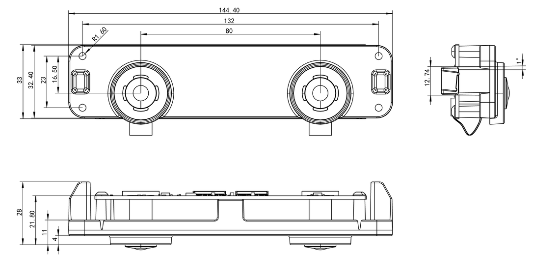
During installation, place washers at the mounting holes and tighten the bolts alternately to avoid minor deformation of the GS130W module metal bracket, which could change the sensor extrinsic parameters.
Hardware Interface Description
Hardware Topology
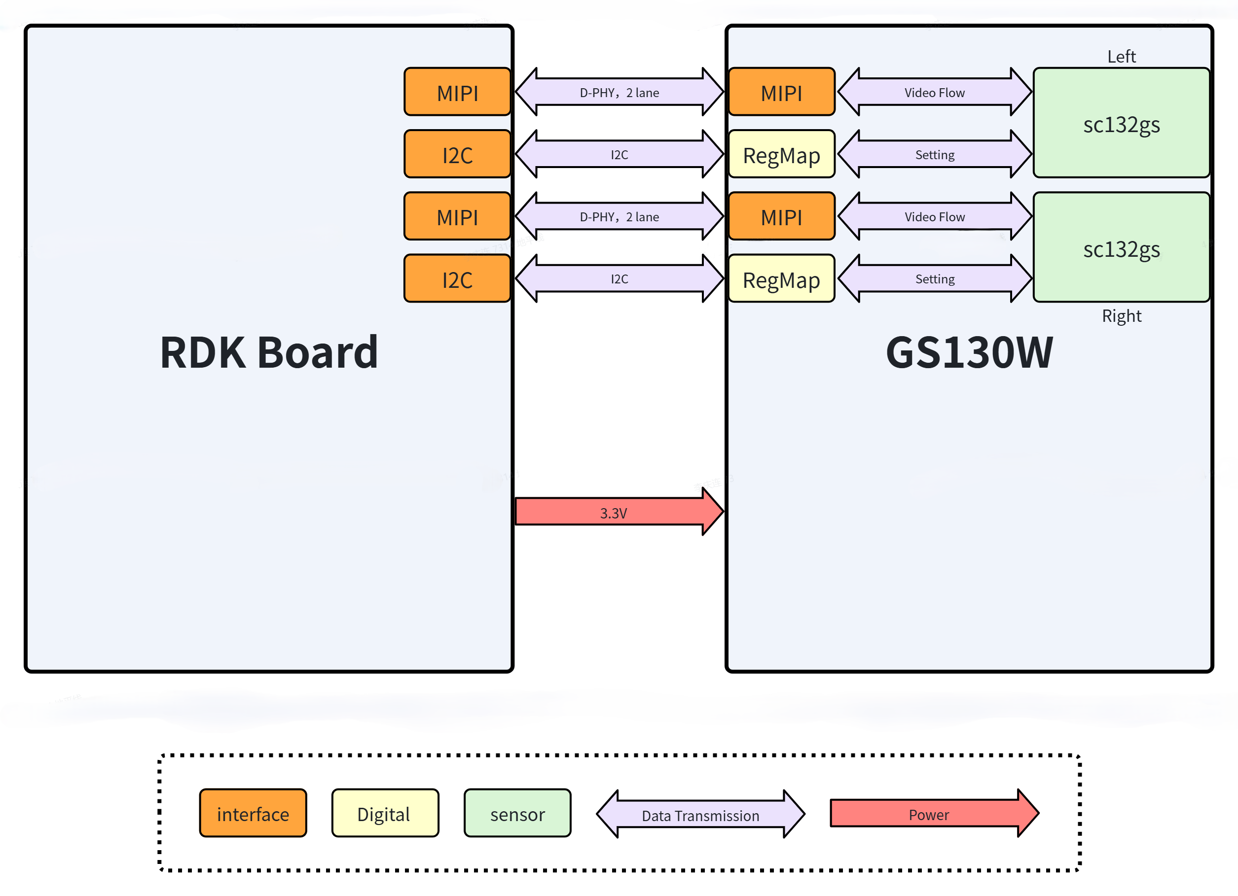
The diagram below shows the hardware topology between the GS130W module and the RDK development board.
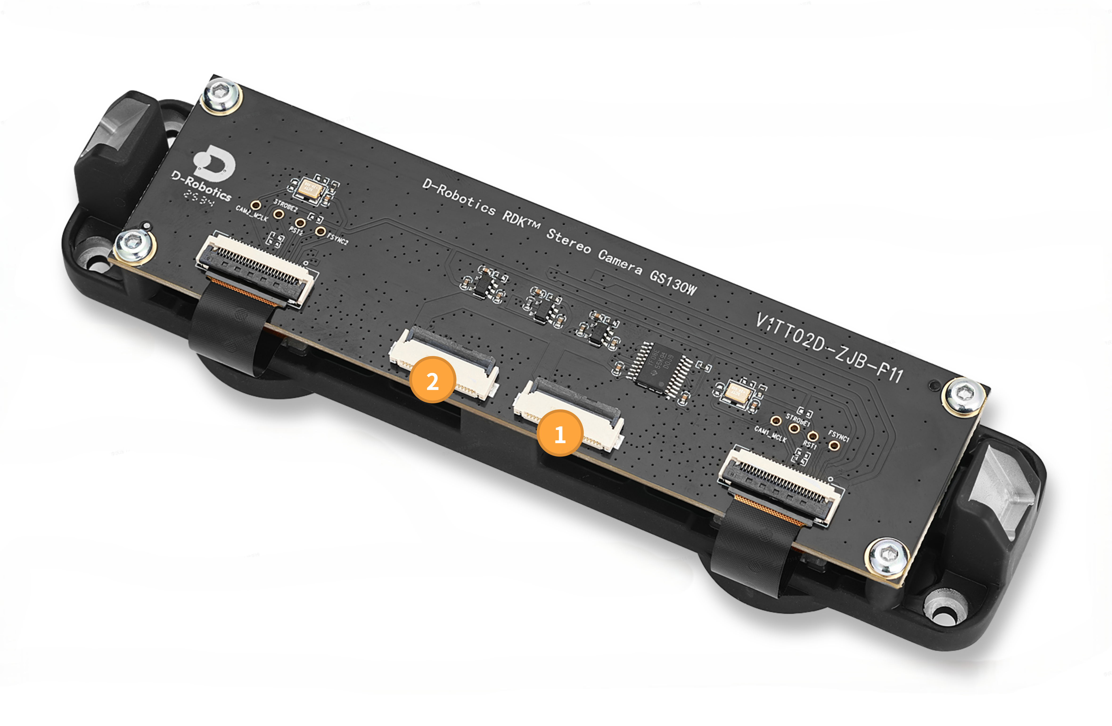
Connector Models
| Connector | Model | Manufacturer |
|---|---|---|
| 1 | AFC24-S22FIA-00 | Jushuo Electronics |
| 2 | AFC24-S22FIA-00 | Jushuo Electronics |
Interface Description
① Right MIPI Camera Interface
This interface is used for right camera and IMU data transmission.
The connector PIN1 position is shown below:

The connector pinout is shown in the table below:
| PIN | Name | Description |
|---|---|---|
| 1 | GND | |
| 2 | MDN0 | MIPI Data Negative 0; used for video stream transmission |
| 3 | MDP0 | MIPI Data Positive 0; used for video stream transmission |
| 4 | GND | |
| 5 | MDN1 | MIPI Data Negative 1; used for video stream transmission |
| 6 | MDP1 | MIPI Data Positive 1; used for video stream transmission |
| 7 | GND | |
| 8 | MCN | MIPI Clock Negative; used for video stream transmission |
| 9 | MCP | MIPI Clock Positive; used for video stream transmission |
| 10 | GND | |
| 11 | N/A | |
| 12 | N/A | |
| 13 | GND | |
| 14 | N/A | |
| 15 | N/A | |
| 16 | GND | |
| 17 | RESET | Connected to the Camera Sensor XSHUTDN pin; used for hardware reset of the sensor chip |
| 18 | FSYNC | Connected to the Camera Sensor TRIGL/FSYNC pin; used to enable exposure for the sensor in Slave mode |
| 19 | GND | |
| 20 | SCL | Connected to the Camera Sensor SCL pin; used for sensor configuration |
| 21 | SDA | Connected to the Camera Sensor SDA pin; used for sensor configuration |
| 22 | 3V3 |
② Left MIPI Camera Interface
This interface is used for left camera data transmission.
The connector PIN1 position is the same as the right MIPI Camera interface.
The connector pinout is shown in the table below:
| PIN | Name | Description |
|---|---|---|
| 1 | GND | |
| 2 | MDN0 | MIPI Data Negative 0; used for video stream transmission |
| 3 | MDP0 | MIPI Data Positive 0; used for video stream transmission |
| 4 | GND | |
| 5 | MDN1 | MIPI Data Negative 1; used for video stream transmission |
| 6 | MDP1 | MIPI Data Positive 1; used for video stream transmission |
| 7 | GND | |
| 8 | MCN | MIPI Clock Negative; used for video stream transmission |
| 9 | MCP | MIPI Clock Positive; used for video stream transmission |
| 10 | GND | |
| 11 | N/A | |
| 12 | N/A | |
| 13 | GND | |
| 14 | N/A | |
| 15 | N/A | |
| 16 | GND | |
| 17 | RESET | Connected to the Camera Sensor XSHUTDN pin; used for hardware reset of the sensor chip |
| 18 | FSYNC | Connected to the Camera Sensor TRIGL/FSYNC pin; used to enable exposure for the sensor in Slave mode |
| 19 | GND | |
| 20 | SCL | Connected to the Camera Sensor SCL pin; used for sensor configuration |
| 21 | SDA | Connected to the Camera Sensor SDA pin; used for sensor configuration |
| 22 | 3V3 |