3.2 Installation
Kit Contents
Prepare the following items before installing the module:
| Item | Image |
|---|---|
| RDK IMU Module | 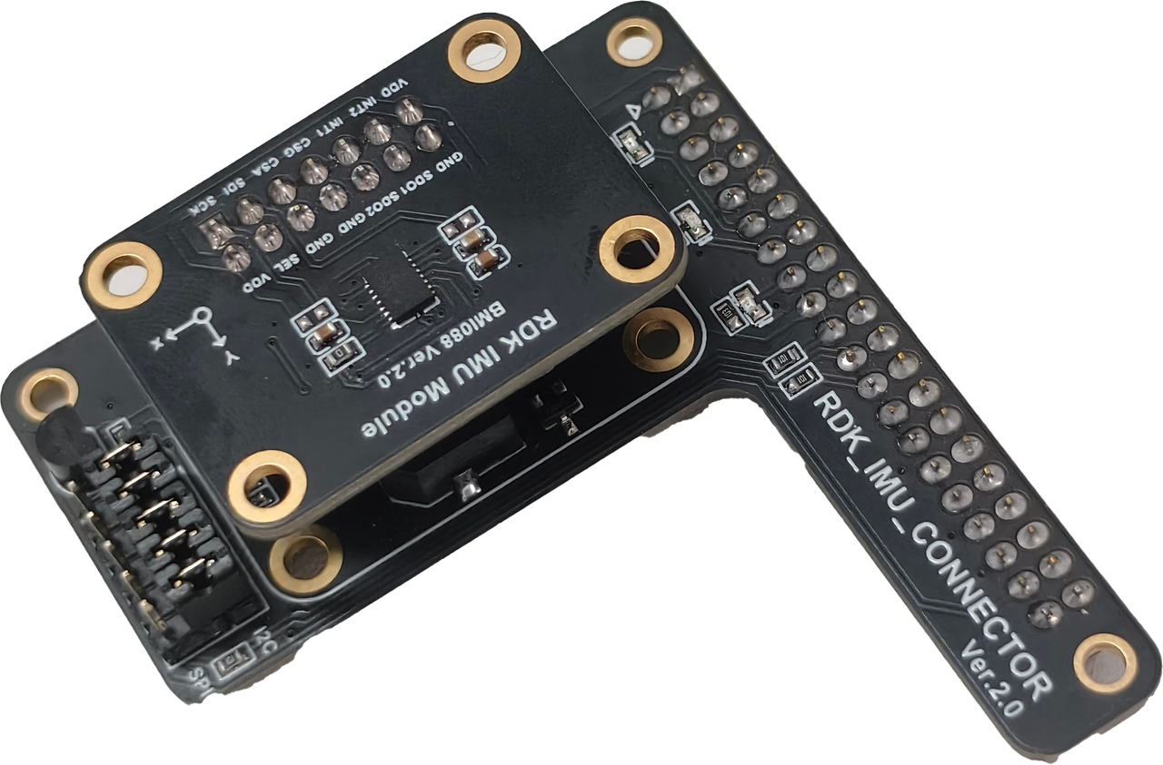 |
| Development board (from supported boards list) | 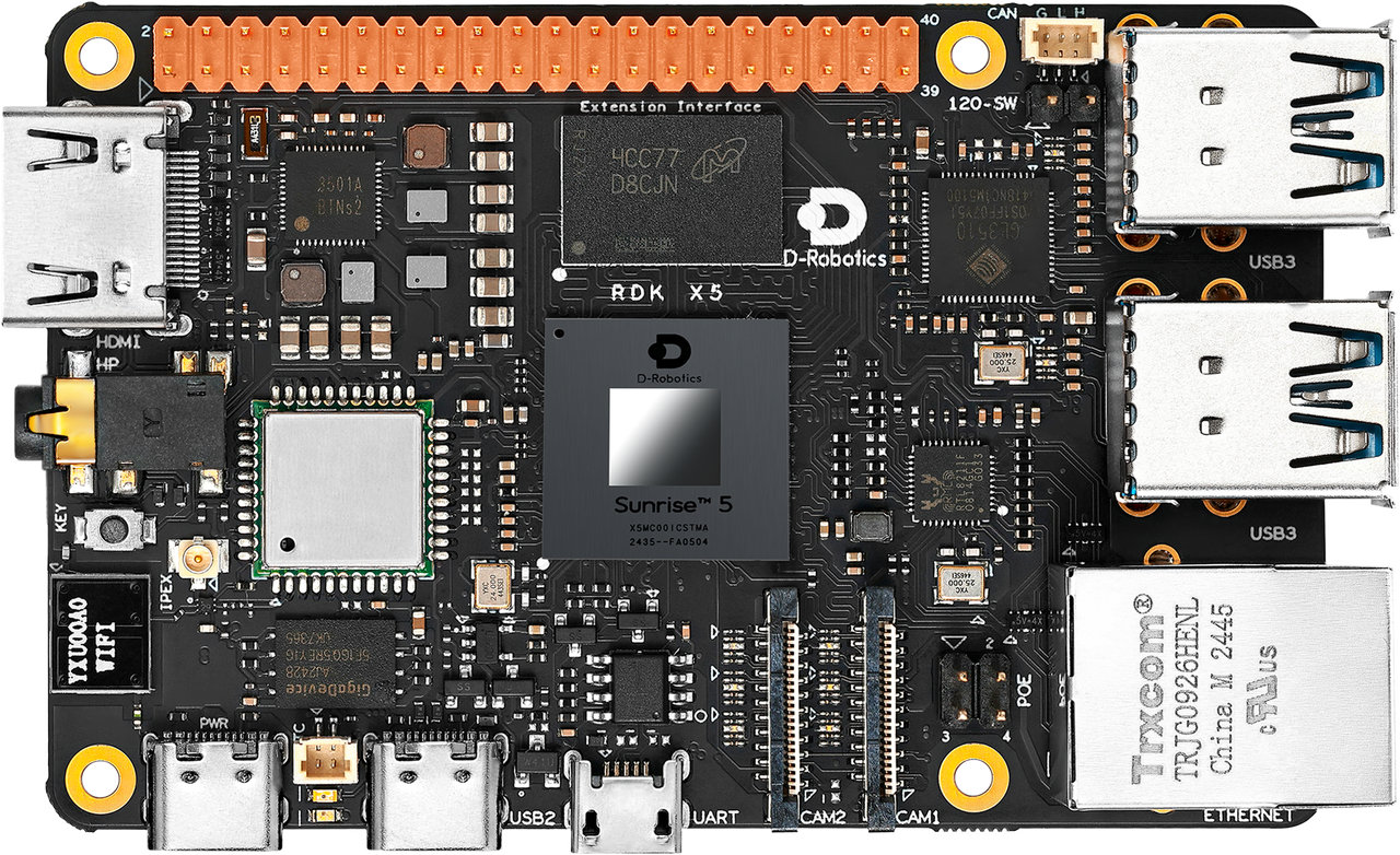 |
Assembly and Connection
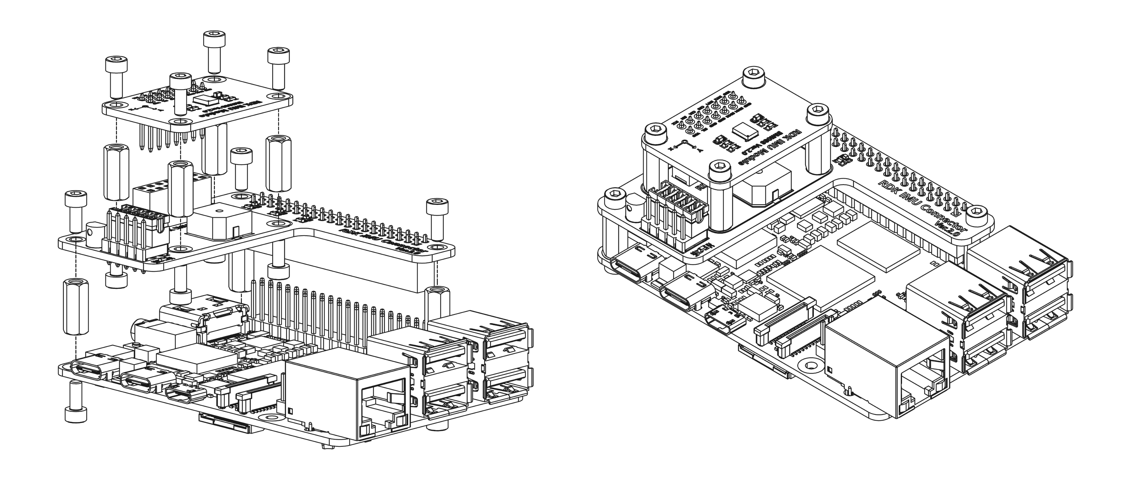
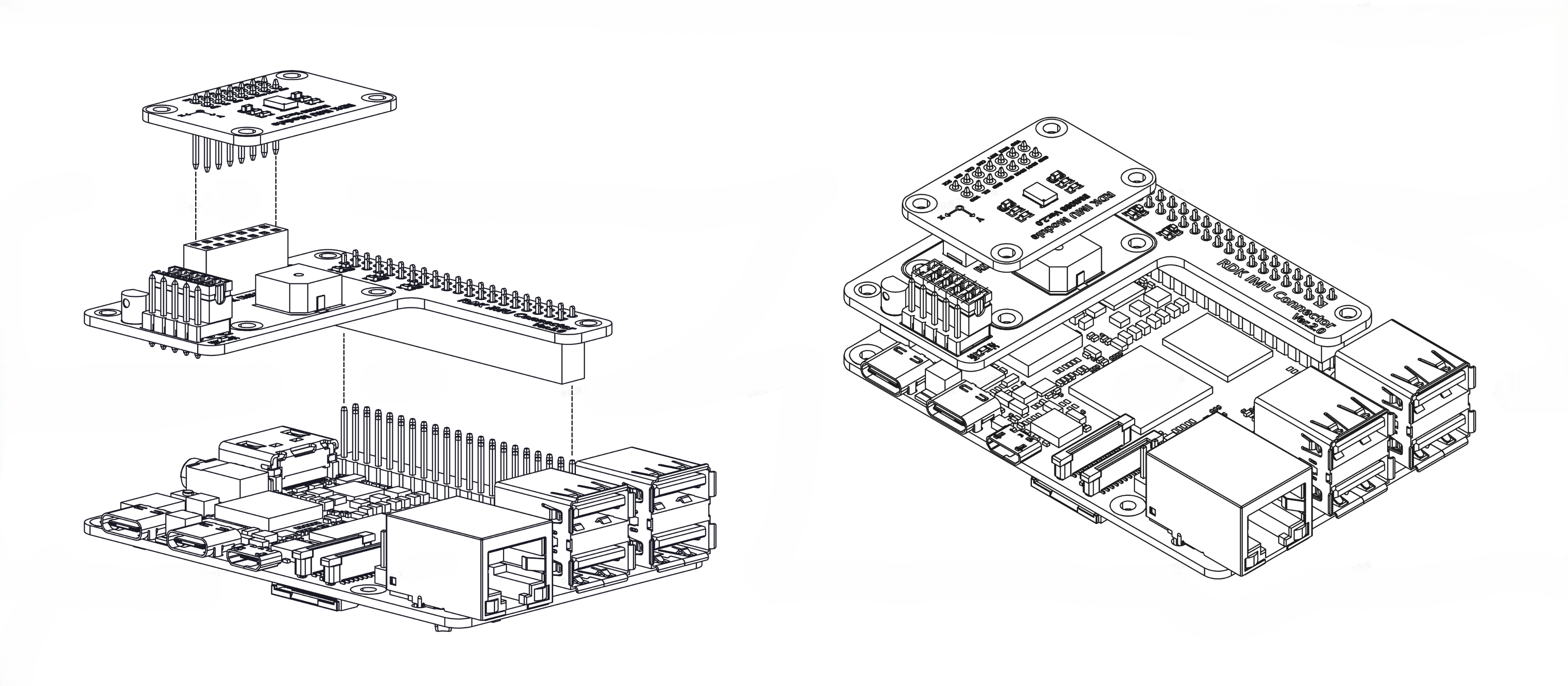
The steps below use the RDK X5 as an example. When connecting to other boards, align the 40-pin header correctly—do not reverse the connection.
- Align the 2×7 pins on the IMU core board with the 2×7 socket on the carrier board and insert vertically.
- Align the 40-pin socket on the carrier board with the 40-pin header on the development board and insert vertically to complete the connection.
To keep the IMU module rigidly attached to the board, you can build a custom support structure. The figure below shows mounting with seven M2.5×11 standoffs and M2.5 screws.