Installation Guide
Bill of Materials
The following items are required to install the module:
| Item Name | Item Image |
|---|---|
| GS130WI module |  |
| Development board (supported board from compatible boards list) |  |
| FFC/FPC cables x2 (22-pin, 0.5 mm pitch, same-side contacts) |  |
| 3-pin cable (1.25 mm slim connector - Dupont wires) |  |
Installation and Connection
Connect FFC/FPC Cables to the GS130WI Module
- When connecting FFC/FPC cables, always power off the development board to prevent device damage from arcing or misaligned contacts.
- FFC/FPC cables are flexible; do not pull them forcefully.
- The back of the GS130WI module has exposed PCB; avoid metal objects falling onto it during installation and use to prevent short circuits.
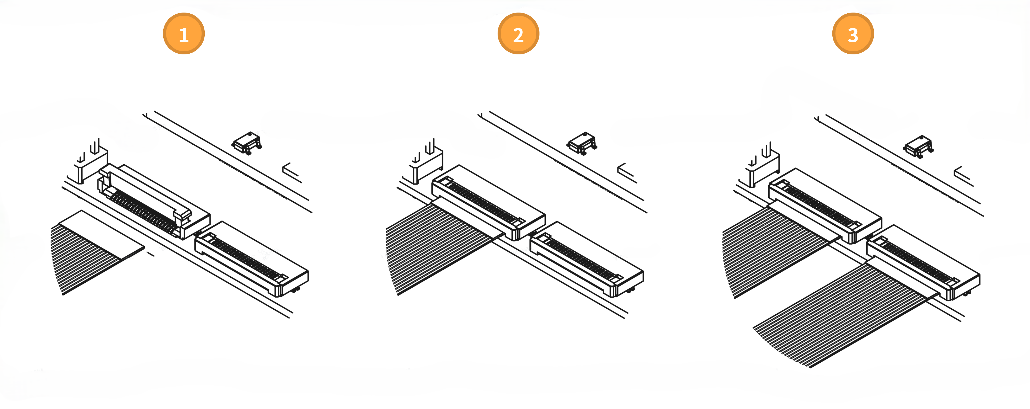
- Open the MIPI Camera connector latch on the GS130WI module.
- Insert one end of the FFC/FPC cable horizontally into the MIPI Camera connector with the contact side facing the PCB, then press the latch closed.
- Repeat for the second FFC/FPC cable to complete the connection between the FFC/FPC cables and the GS130WI module MIPI Camera interfaces.
The GS130W module and GS130WI module require opposite FFC/FPC cable insertion directions. Pay attention to distinguish them and do not reverse the connection.
Connect FFC/FPC Cables to the Development Board
- RDK X5
- RDK X5 Module
- RDK S100/S100P
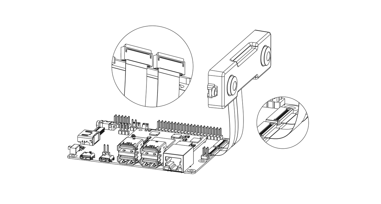
- Open the MIPI Camera connector latch on the RDK X5.
- Insert the other end of the FFC/FPC cable vertically into the MIPI Camera connector with the contact side facing the Ethernet port, then press the connector latch closed.
- Repeat for the second FFC/FPC cable to complete the connection between the FFC/FPC cables and the RDK X5 MIPI Camera interfaces.

After installation, the overall connection of the GS130WI module, RDK X5, and FFC/FPC cables is shown below.

- Open the MIPI Camera connector latch on the RDK X5 Module carrier board.
- Insert the other end of the FFC/FPC cable horizontally into the MIPI interface with the contact side facing the PCB, then press the connector latch closed.
- Repeat for the second FFC/FPC cable to complete the connection between the FFC/FPC cables and the RDK X5 Module carrier board MIPI Camera interfaces.
After installation, the overall connection of the GS130WI module, RDK X5 Module, and FFC/FPC cables is shown below.
- Open the MIPI Camera connector latch on the RDK S100 with Camera expansion board installed.
- Insert the other end of the FFC/FPC cable horizontally into the MIPI Camera connector with the contact side facing the PCB, then press the connector latch closed.
- Repeat for the second FFC/FPC cable to complete the connection between the FFC/FPC cables and the RDK S100 MIPI Camera interfaces.

After installation, the overall connection of the GS130WI module, RDK S100, and FFC/FPC cables is shown below.

Connect the IMU Timestamp Interface
This interface is used for IMU hardware timestamping. Whether it needs to be connected and the wire sequence depend on software requirements. Refer to your actual software requirements.
Insert the slim connector side of the 3-pin cable into the slim connector interface on the GS130WI module with the gold fingers facing outward on the PCB.

The Dupont connector side is used to connect to development board pins or other interfaces for IMU hardware timestamping.