2.3. X5 MD 开发板使用指南
2.3.1. 功能概述
2.3.1.1. 产品介绍
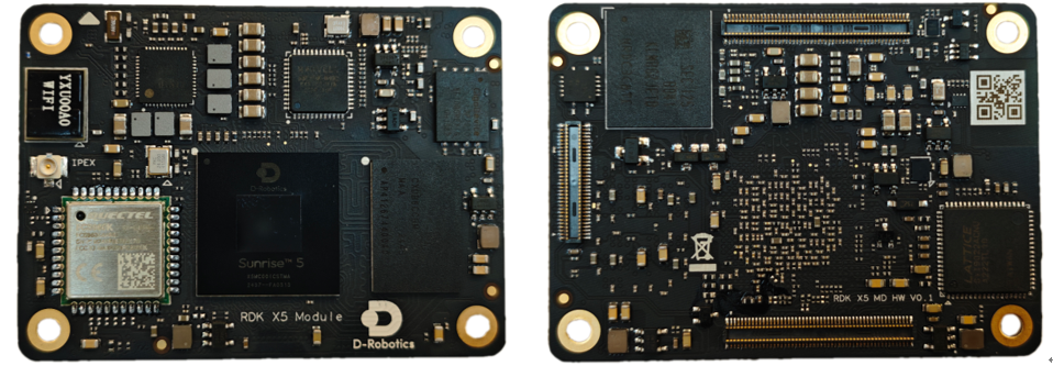
X5 MD采用
RDK X5 Module作为
RDK X5 Module Carrier Board是RDK X5 Module的
两路22Pin摄像头
接口(集成MIPI CSI、LPWM&MCLK、I²C、GPIO) 一路HDMI接口
一路RJ45以太网
接口 一路LCD接口(集成MIPI DSI和I²C)
40Pin扩展
接口(包含GPIO、I²C、SPI、I²S、PWM) 多路
功能 控制 接口 等
经过IO载板
CAN总线
接口(采用TCAN4550芯片,SPI转CAN) 耳机
音频接口(基于ES8326B,支持I²S转 音频DAC&ADC) 四路USB 3.0接口(通过GL3510 USB Hub扩展)
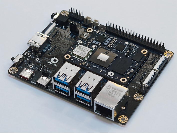
用户
2.3.1.2. 规格参数
X5 MD基础
| 模块 | 参数 |
|---|---|
| 处理器 | Sunrise 5 ( X5 ) 芯片 |
| CPU | 8 核 ARM ® Cortex ® A55@1.5GHz |
| BPU | Bayers-architecture BPU@1.0GHz, 10 TOPS |
| 存储 | 2GB/4GB/8GB LPDDR4 , 0/8GB/16GB/32GB/64GB eMMC |
| 摄像头 | 2 路 4-lane MIPI CSI 接口 |
| 显示 | 1 路 HDMI 1080P@60fps , 1 路 MIPI DSI 2K@30fps |
| USB | 1 路 USB Type-A 3.0 接口 , 1 路 Micro USB 2.0 接口 |
| 有线 |
1 路 |
| 无线网络 | 2.4G / 5G Wi-Fi x1 ,支持 802.11 b/g/n、 Bluetooth 5.1 |
| 其他 |
TF 卡 |
| 供电 | USB Type C 5V/5A 供电 |
2.3.1.3. X5 MD 配件说明
用户
必选
USB Type C 接口 5V/5A 的
电源适配器 千兆
网线 x1 ,用于 网络通讯 Micro USB 2.0 数据线 x1,用于
串口 通信 USB TYPE-C 数据线 x1,用于USB 2.0 数据传输
Camera 模组,用于
视频、图像 功能 评测
可
显示器
与 HDMI Type-A 接口 线缆,用于 视频 画面 预览 MIPI LCD 显示屏
与 22PIN FPC,用于 显示 功能测试 Audio 子板,用于
语音 功能测试
2.3.2. IO载板功能模块布局
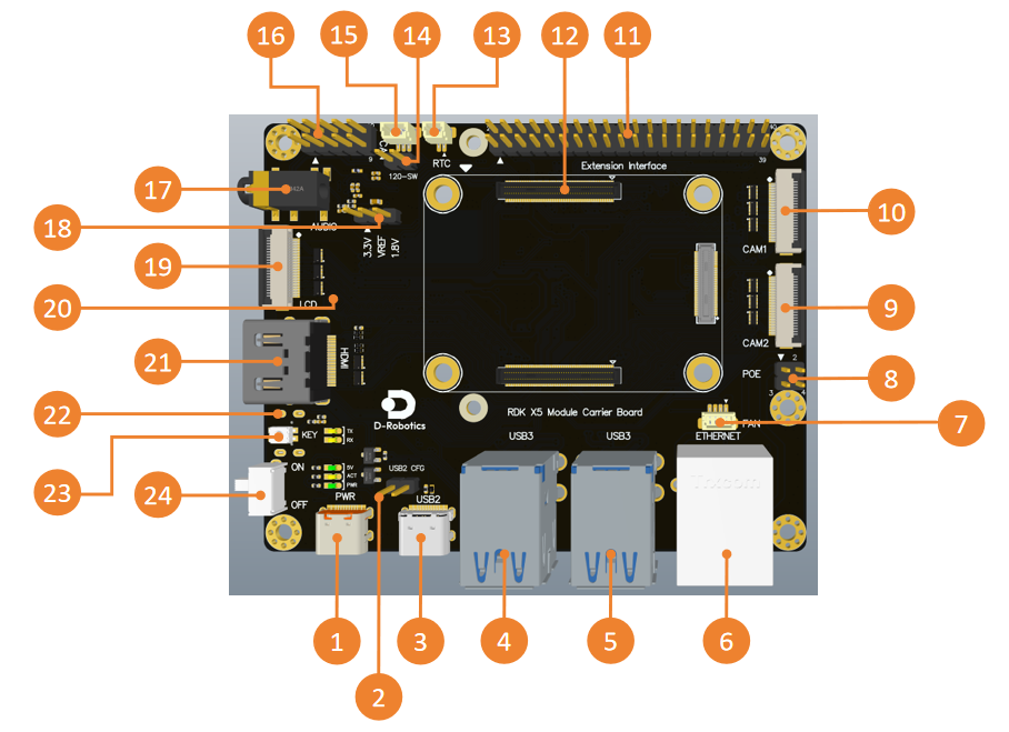
| 接口 | 功能 | 接口 | 功能 |
|---|---|---|---|
| 1 | USB Type C 5V/5A供电 |
13 | RTC电池 |
| 2 | USB2.0配置header | 14 | CAN终端 |
| 3 | USB2.0接口 | 15 | CAN总线 |
| 4 | USB3.0 HOST接口x2 | 16 | 功能 |
| 5 | USB3.0 HOST接口x2 | 17 | Audio接口 |
| 6 | 千兆 |
18 | IO电平 |
| 7 | 风扇 |
19 | MIPI DSI接口 |
| 8 | POE 接口 | 20 | Micro SD卡 |
| 9 | CAM2接口,4lane | 21 | HDMI接口 |
| 10 | CAM1接口,4lane | 22 | Debug口,USB转 |
| 11 | 40pin header | 23 | Sleep按键 |
| 12 | 核心 |
24 | 电源开关 |
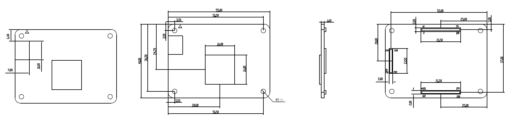
2.3.2.1. 尺寸图
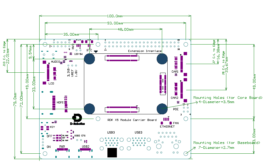
2.3.3. 接口使用说明
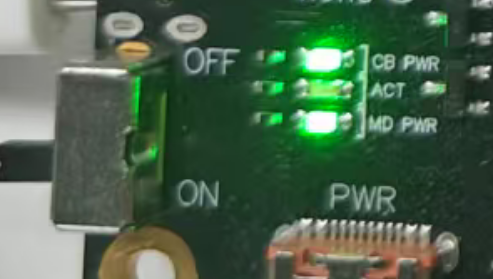
2.3.3.1. 启动开发板
接入 5V/5A 电源适配器(接口 1 ),将
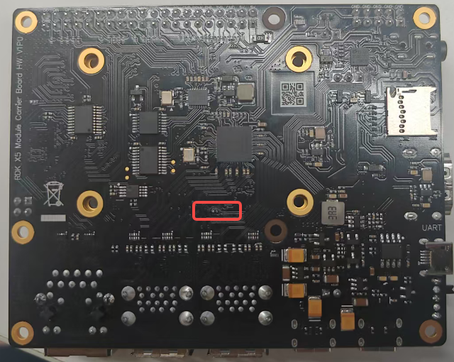
2.3.3.2. 从 eMMC 启动
X5 MD最spi nand启动,如果eMMC启动。
首先,通过
V0.X版本:需要eMMC启动
V1.X版本:需要
2.3.3.3. 调试串口
开发板
波特率(Baud rate):921600
数据位(Data bits):8
奇偶校验(Parity):None
停止
位(Stop bits):1 流控(Flow Control):无
串口

2.3.3.4. 以太网
开发板ip 地址192.168.1.10。 如需ifconfig 命令eth0 节点
root@buildroot:~$ ifconfig
eth0: flags=4163<UP,BROADCAST,RUNNING,MULTICAST>  mtu 1500
        inet 192.168.1.10  netmask 255.255.255.0  broadcast 0.0.0.0
        ether 9a:77:34:d1:fc:ed  txqueuelen 1000  (Ethernet)
        RX packets 1813  bytes 134485 (131.3 KiB)
        RX errors 0  dropped 1  overruns 0  frame 0
        TX packets 4563  bytes 282810 (276.1 KiB)
        TX errors 0  dropped 0 overruns 0  carrier 0  collisions 0
        device interrupt 38
此外,该
2.3.3.5. USB 3.0 接口
开发板
如果
使能 USB 3.0 Device 模式
通过
设置 USB 3.0 为 Device 模式
echo device > /sys/class/usb_role/35100000.usb-role-switch/role
设置 USB 3.0 为 Host 模式
echo host > /sys/class/usb_role/35100000.usb-role-switch/role
2.3.3.6. USB 2.0 接口
开发板
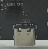
该
功能
调试,默认 adb 模式,可 通过 命令 切换 rndis、 uvc 等 功能 镜像
烧录,支持 dfu、 fastboot 等 模式 的 烧录 功能 外设
接入,配合 接口 3,灵活 切换host和device模式
2.3.3.7. IO电平选择
开发板
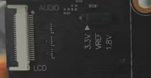
2.3.3.8. 摄像头 (MIPI CSI) 接口
开发板
两路
| 接口 | MIPI CSI Host | 最大 |
I2C Bus | 复位 GPIO | LPWM & MCLK |
|---|---|---|---|---|---|
| 10 | MIPI_CSI0&1 | 4 lane | I2C6 | LSIO_GPIO1_06 - 353 | LSIO_LPWM1_0 & LSIO_SENSOR0_MCLK |
| 9 | MIPI_CSI2&3 | 4 lane | I2C4 | LSIO_GPIO1_04 - 351 | LSIO_LPWM1_1 & LSIO_SENSOR1_MCLK |
22pin接口IMX219、IMX477、OV5647,MCLK由
官方
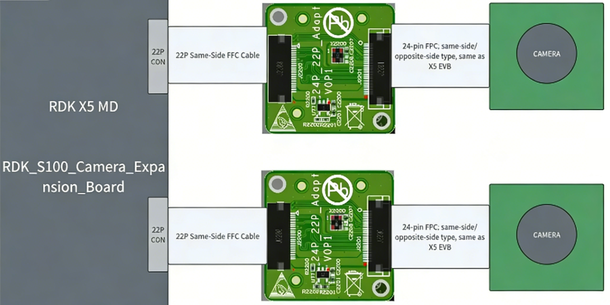
X5 MD 与
通过SC230AI、SC132gs、IMX415,方便
安装
查询
echo 353 > /sys/class/gpio/export
echo out > /sys/class/gpio/gpio353/direction
echo 0 > /sys/class/gpio/gpio353/value
sleep 0.1
echo 1 > /sys/class/gpio/gpio353/value

i2cdetect -y -r 6
查询CAM2(接口9) 接口 上 Camera Sensor 的 I2C 设备
echo 351 > /sys/class/gpio/export
echo out > /sys/class/gpio/gpio351/direction
echo 0 > /sys/class/gpio/gpio351/value
sleep 0.1
echo 1 > /sys/class/gpio/gpio351/value

i2cdetect -y -r 4
成功
root@buildroot:~$ i2cdetect -y -r 6
     0  1  2  3  4  5  6  7  8  9  a  b  c  d  e  f
00:                         -- -- -- -- -- -- -- --
10: -- -- -- -- -- -- -- -- -- -- -- -- -- -- -- --
20: -- -- -- -- -- -- -- -- -- -- -- -- -- -- -- --
30: 30 -- -- -- -- -- -- -- -- -- -- -- -- -- -- --
40: -- -- -- -- -- -- -- -- -- -- -- -- -- -- -- --
50: -- -- -- -- -- -- -- -- -- -- -- -- -- -- -- --
60: -- -- -- -- -- -- -- -- -- -- -- -- -- -- -- --
70: -- -- -- -- -- -- -- --
更
2.3.3.9. HDMI 接口
开发板
由于
2.3.3.10. LCD ( MIPI DSI)和 TP 接口
开发板
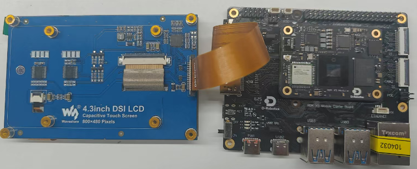
成功
modprobe sii902x
modprobe panel-wh-cm480
modprobe ft5406
modprobe hb_bl
modprobe vio_n2d
modprobe vs-x5-syscon-bridge
modprobe vs_drm
串口
[ 3343.383052] vs-disp-sif 3e080000.vs-sif: Adding to iommu group 3
[ 3343.384118] vs-dc 3e000000.dc8000Nano: Adding to iommu group 4
[ 3343.385252] vs-bt1120 3e010000.bt1120: Adding to iommu group 5
[ 3343.387555] horizon-lsio-pinctrl 34180000.lsio_iomuxc: set pin = 14 direction to input
[ 3343.387567] horizon-lsio-pinctrl 34180000.lsio_iomuxc: map pin14 to gpio[0] - 14
[ 3343.387635] panel-jc-050hd134 3e060000.mipi_dsi0.0: supply power not found, using dummy regulator
[ 3343.391241] vs-drm 3e000000.disp_apb:display-subsystem: bound 3e080000.vs-sif (ops sif_component_ops [vs_drm])
[ 3343.391529] vs-drm 3e000000.disp_apb:display-subsystem: bound 3e000000.dc8000Nano (ops dc_component_ops [vs_drm])
[ 3343.391692] vs-drm 3e000000.disp_apb:display-subsystem: bound 3e010000.bt1120 (ops bt1120_component_ops [vs_drm])
[ 3343.391730] vs-drm 3e000000.disp_apb:display-subsystem: bound 3e000000.disp_apb:bt1120_bridge (ops bt1120_bridge_component_ops [vs_drm])
[ 3343.391764] vs-drm 3e000000.disp_apb:display-subsystem: bound 3e000000.disp_apb:bt1120_bridge_wb (ops bt1120_bridge_component_ops [vs_drm])
[ 3343.391816] vs-drm 3e000000.disp_apb:display-subsystem: bound 3e060000.mipi_dsi0 (ops dsi_component_ops [vs_drm])
[ 3343.391917] vs-drm 3e000000.disp_apb:display-subsystem: bound 3e000000.disp_apb:dsi-encoder (ops encoder_component_ops [vs_drm])
[ 3343.391976] vs-drm 3e000000.disp_apb:display-subsystem: bound 3e000000.disp_apb:hdmi-encoder (ops encoder_component_ops [vs_drm])
[ 3343.392815] [drm] Initialized vs-drm 1.0.0 20191101 for 3e000000.disp_apb:display-subsystem on minor 0
play-subsystem on minor 0
当[drm] Initialized vs-drm 1.0.0 20191101 for 3e000000.disp_apb:display-subsystem on minor 0 表示
使用 modetest -M vs-drm -a -s 73@31:800x480 -P 33@31:800x480@NV12 命令
连接

加载ft5406是hb_bl是
驱动/dev/input/event1 设备
测试
使用 tc_test 程序
# ./tc_test /dev/input/event1
Monitoring input events on /dev/input/event1
[/dev/input/event1] event(0): type:3; code: 47; value:  0; realx:  0; realy:  0
[/dev/input/event1] event(1): type:3; code: 57; value: 16; realx:  0; realy:  0
[/dev/input/event1] event(2): type:3; code: 53; value:248; realx:248; realy:  0
[/dev/input/event1] event(3): type:3; code: 54; value:1007; realx:248; realy:1007
[/dev/input/event1] event(4): type:3; code: 48; value: 13; realx:248; realy:1007
[/dev/input/event1] event(5): type:3; code: 58; value: 13; realx:248; realy:1007
测试代码:
#include <stdio.h>
#include <stdlib.h>
#include <fcntl.h>
#include <unistd.h>
#include <linux/input.h>

static int handle_event(int fd, const char *device_name)
{
	struct input_event ev[64];
	int button = 0, realx = 0, realy = 0, i, rd;

	rd = read(fd, ev, sizeof(struct input_event) * 64);
	if (rd < (int)sizeof(struct input_event)) return 0;

	for (i = 0; i < rd / (int)sizeof(struct input_event); i++)
	{
		if (EV_ABS == ev[i].type)
		{
			if (ev[i].code == 53) {
				realx = ev[i].value;
			} else if (ev[i].code == 54) {
				realy = ev[i].value;
			}
		}
		printf("[%s] event(%d): type:%d; code:%3d; value:%3d; realx:%3d; realy:%3d\n",
			   device_name, i, ev[i].type, ev[i].code, ev[i].value, realx, realy);
	}
	return 1;
}

int main(int argc, char *argv[])
{
	if (argc < 2) {
		printf("Usage: %s <event device path>\n", argv[0]);
		return -1;
	}

	const char *device_path = argv[1];
	int fd = open(device_path, O_RDONLY);
	if (fd < 0) {
		printf("Failed to open input device: %s\n", device_path);
		return -1;
	}

	printf("Monitoring input events on %s\n", device_path);
	while (handle_event(fd, device_path));

	close(fd);
	return 0;
}
2.3.3.11. Wi-Fi 天线
V1P1 及板载天线 与 外置天线 两种
#天线控制初始化
echo 428 > /sys/class/gpio/export
echo 429 > /sys/class/gpio/export
echo out > /sys/class/gpio/gpio428/direction
echo out > /sys/class/gpio/gpio429/direction

#切换为板载天线
echo 1 > /sys/class/gpio/gpio428/value
echo 0 > /sys/class/gpio/gpio429/value

#切换为外部天线
echo 0 > /sys/class/gpio/gpio428/value
echo 1 > /sys/class/gpio/gpio429/value
2.3.3.12. Wi-Fi / Bluetooth
使用 Wi-Fi
开发板
root@buildroot:~$ ifconfig wlan0
wlan0: flags=4098<BROADCAST,MULTICAST>  mtu 1500
        ether 40:9c:a7:70:98:cc  txqueuelen 1000  (Ethernet)
        RX packets 0  bytes 0 (0.0 B)
        RX errors 0  dropped 0  overruns 0  frame 0
        TX packets 0  bytes 0 (0.0 B)
        TX errors 0  dropped 0 overruns 0  carrier 0  collisions 0
用户
# 进入 userdata 目录,避免在系统目录下遇到无法写文件的错误
cd /userdata/
# 根据 Wi-Fi 热点情况修改命令中的热点名( SSID)和密码(“ WIFI_SSID”,“ WIFI_PASSWD”)
wpa_passphrase "WIFI_SSID" "WIFI_PASSWD"  >> ./wpa_supplicant.conf

sleep 1
wpa_supplicant -D nl80211 -i wlan0 -c ./wpa_supplicant.conf -B
sleep 1
udhcpc -i wlan0 &
配置ping 8.8.8.8 命令
root@buildroot:~$ cd /userdata/
root@buildroot:/userdata$ wpa_passphrase WiFi-Test 12345678 >> ./wpa_supplicant.conf
root@buildroot:/userdata$ wpa_supplicant -D nl80211 -i wlan0 -c ./wpa_supplicant.conf -B
Successfully initialized wpa_supplicant
[10093.447698] [BB][halbb_la_bb_set_smp_rate] smp_rate_tmp=7, la_smp_rate_log=160 M
root@buildroot:/userdata$ udhcpc -i wlan0 &
[1] 1309
udhcpc: started, v1.35.0
root@buildroot:/userdata$ udhcpc: broadcasting discover
udhcpc: broadcasting select for 192.168.137.252, server 192.168.137.1
udhcpc: lease of 192.168.137.252 obtained from 192.168.137.1, lease time 604800
deleting routers
adding dns 192.168.137.1

[1]+  Done                    udhcpc -i wlan0
root@buildroot:/userdata$ ifconfig wlan0
wlan0: flags=4163<UP,BROADCAST,RUNNING,MULTICAST>  mtu 1500
        inet 192.168.137.252  netmask 255.255.255.0  broadcast 192.168.137.255
        ether 40:9c:a7:70:98:cc  txqueuelen 1000  (Ethernet)
        RX packets 117  bytes 15326 (14.9 KiB)
        RX errors 0  dropped 1  overruns 0  frame 0
        TX packets 63  bytes 5056 (4.9 KiB)
        TX errors 0  dropped 0 overruns 0  carrier 0  collisions 0

root@buildroot:/userdata$ ping 8.8.8.8
PING 8.8.8.8 (8.8.8.8): 56 data bytes
64 bytes from 8.8.8.8: seq=0 ttl=52 time=82.124 ms
64 bytes from 8.8.8.8: seq=1 ttl=52 time=106.029 ms
64 bytes from 8.8.8.8: seq=2 ttl=52 time=129.993 ms
^ C
--- 8.8.8.8 ping statistics ---
3 packets transmitted, 3 packets received, 0% packet loss
round-trip min/avg/max = 82.124/106.048/129.993 ms
root@buildroot:/userdata$
Wi-Fi 的 STA 和 AP 模式/etc/init.d/wifi_init.sh ap 可以/etc/init.d/wifi_init.sh sta 可以
root@buildroot:~# /etc/init.d/wifi_init.sh ap
Initialize wlan0 to ap mode
wlan0: interface state UNINITIALIZED->ENABLED
wlan0: AP-ENABLED
Finish initialize wlan0 to ap mode
dnsmasq: started, version 2.86 cachesize 150
root@buildroot:~# dnsmasq: compile time options: IPv6 GNU-getopt DBus no-UBus no-i18n no-IDN DHCP DHCPv6 no-Lua TFTP no-conntrack ipset auth no-cryptohash no-DNSSEC loop-detect inotify dumpfile
dnsmasq: warning: no upstream servers configured
dnsmasq-dhcp: DHCP, IP range 192.168.5.2 -- 192.168.5.254, lease time 12h
dnsmasq: read /etc/hosts - 2 addresses

root@buildroot:~# /etc/init.d/wifi_init.sh sta
Initialize wlan0 to station mode
Finish initialize wlan0 to station mode
使用 Bluetooth
执行 /etc/init.d/bt_init.sh 完成
执行 bluetoothctl 进入show 来powered 和 discoverable 状态。
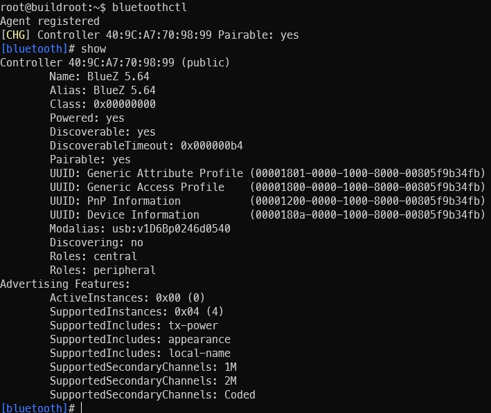
执行 power on 使能

为了discoverable on 打开

此时
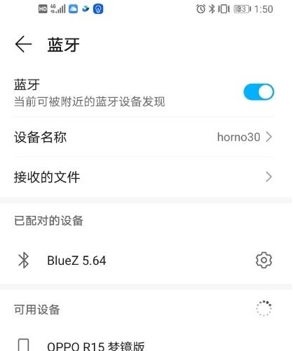
接下来
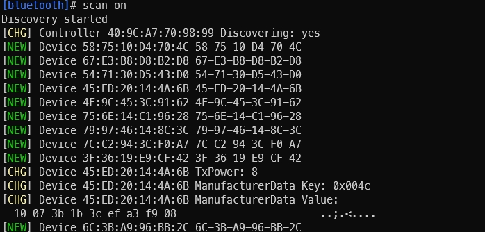
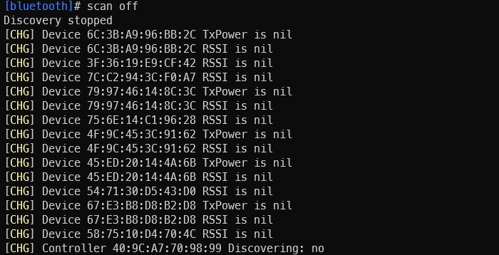
然后
配对pair [targetMAC] ,输入yes,对端配对 选项
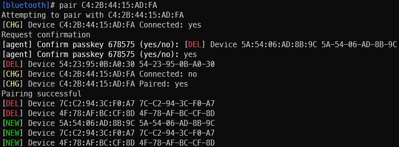
配对trust [targetMAC] 来
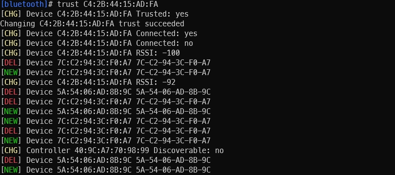
使用 l2ping 测试

2.3.3.13. TF 卡
开发板
插上 TF 卡后,内核
[ 9809.931894] mmc1: new HSSDHC card at address 1234
[ 9809.933740] mmcblk1: mmc1:1234 SA16G 14.5 GiB
[ 9809.940060]  mmcblk1: p1
注意:根据 TF 卡
TF 卡上
的 分区 文件系统 格式 不是 FAT32 ( VFAT)、 ext2 、 ext3 、 ext4 ,请 使用 以下 命令 对 TF 卡 分区 进行 格式化
# 格式为 FAT32(VFAT)
mkfs.vfat /dev/mmcblk2p1
# 格式为 ext4
mkfs.ext4 /dev/mmcblk2p1
# 格式为 ext3
mkfs.ext3 /dev/mmcblk2p1
# 格式为 ext2
mkfs.ext2 /dev/mmcblk2p1
2.3.3.14. CANFD 接口
开发板
CANFD 接口

2.3.3.15. 40PIN 接口
开发板
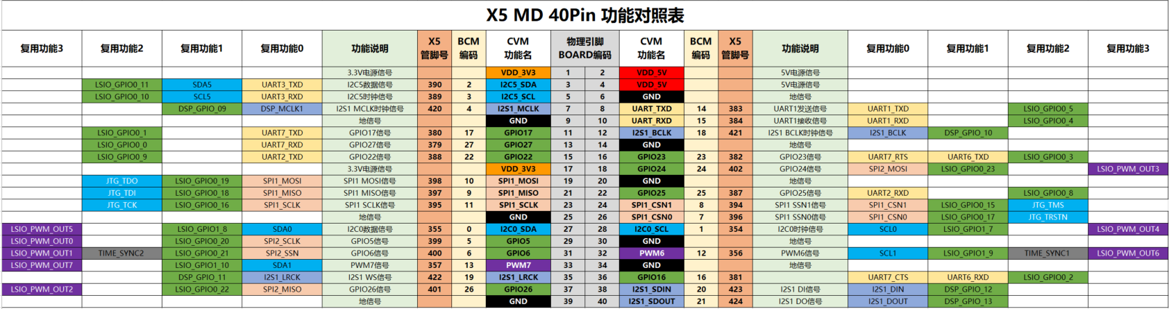
40PIN 上
连接举例:
这里
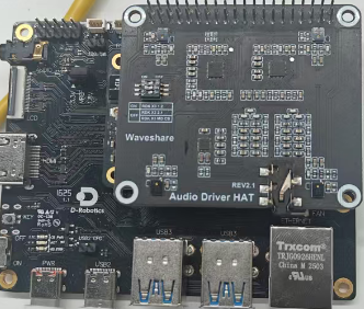
2.3.3.16. RTC
开发板

连接器
hpu3501-rtc 被rtc0 ,可以
# 确认是否存在 /dev/rtc0 设备
ls /dev/rtc*

# 建立 /dev/rtc0 到 /dev/rtc 的软连接
rm /dev/rtc
ln -s /dev/rtc0 /dev/rtc

# 将时间写入外部 rtc
date -s "2024/01/01 17:08:00"    # 设置系统时间
hwclock -w                       # 将系统时间写入 RTC
hwclock -r                       # 读取 RTC 时间,确认时间是否写入成功

# 重启单板后从外部 RTC 读取时间到系统
# 确认是否存在 /dev/rtc0 设备
ls /dev/rtc*
# 建立 /dev/rtc0 到 /dev/rtc 的软连接
rm /dev/rtc
ln -s /dev/rtc1 /dev/rtc
hwclock -s                               # 如果 rtc 电池存在,断电后,再上电,可以将 RTC 时间更新到系统时间
date                                     # 读取系统时间,此时应该是先前配置的时间 "2024/01/01 17:08:00"
2.3.3.17. 其他接口
电源开关
控制
复位开关
整版
唤醒
开关
用于