Hardware description
Mounting instructions
RDK Audio Expansion Board
The RDK Audio Expansion Board has 4 plated mounting holes on its edges, and can be secured with 4 × M2.5 screws.

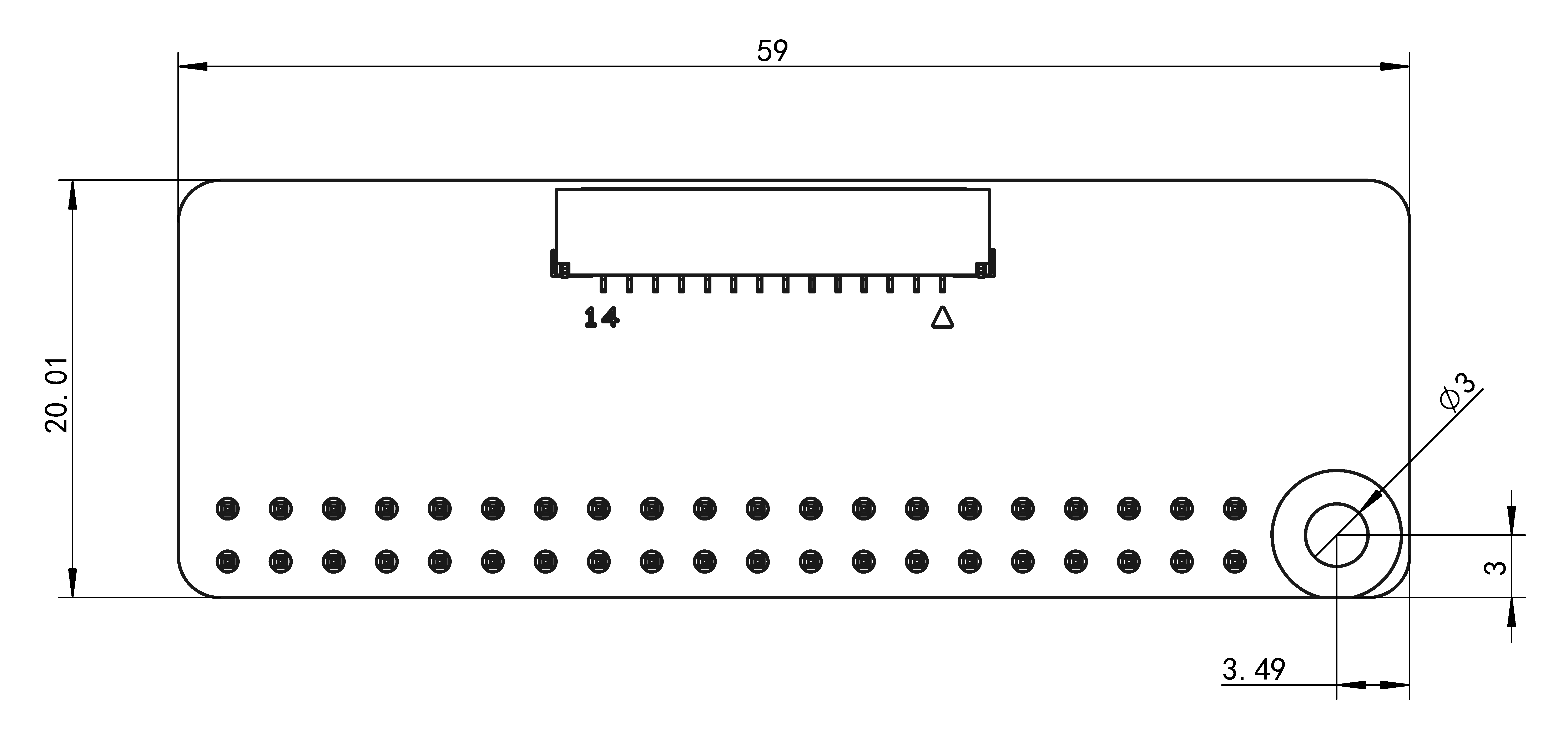
RDK Audio Expansion Board Adapter
The RDK Audio Expansion Board Adapter has 1 plated mounting hole, and can be secured with 1 × M2.5 screw, working with the 40PIN interface for firm mounting.
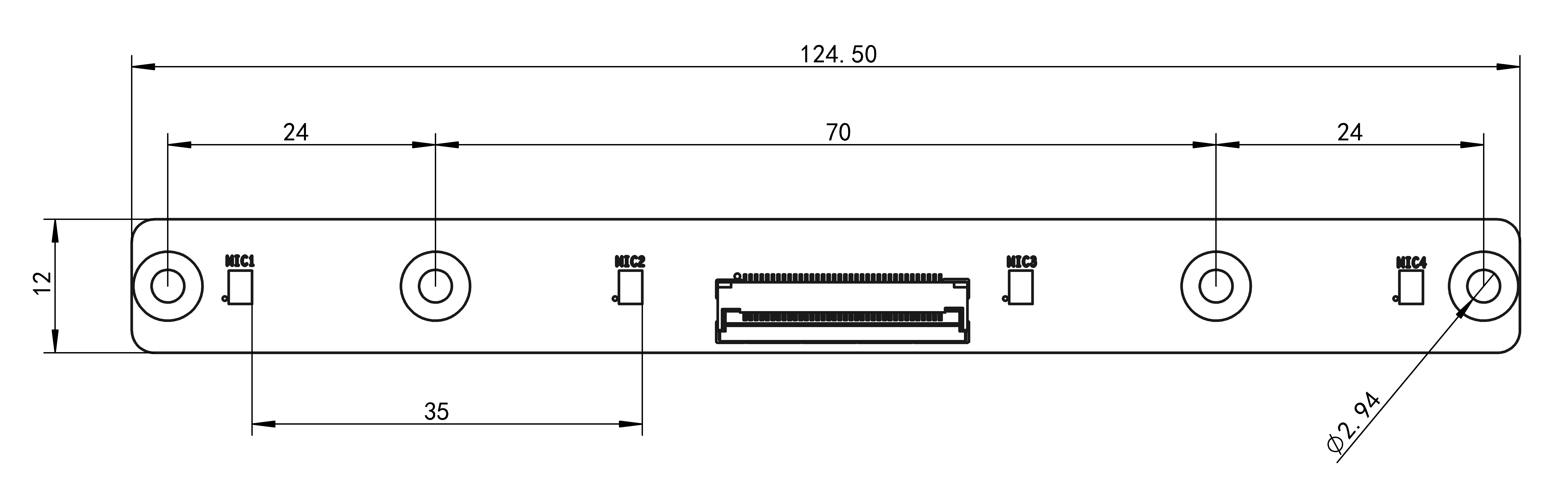
RDK Audio Expansion Board 4-Mic Array
The RDK Audio Expansion Board 4-Mic Array has 4 plated mounting holes, and can be secured with 4 × M3 screws.
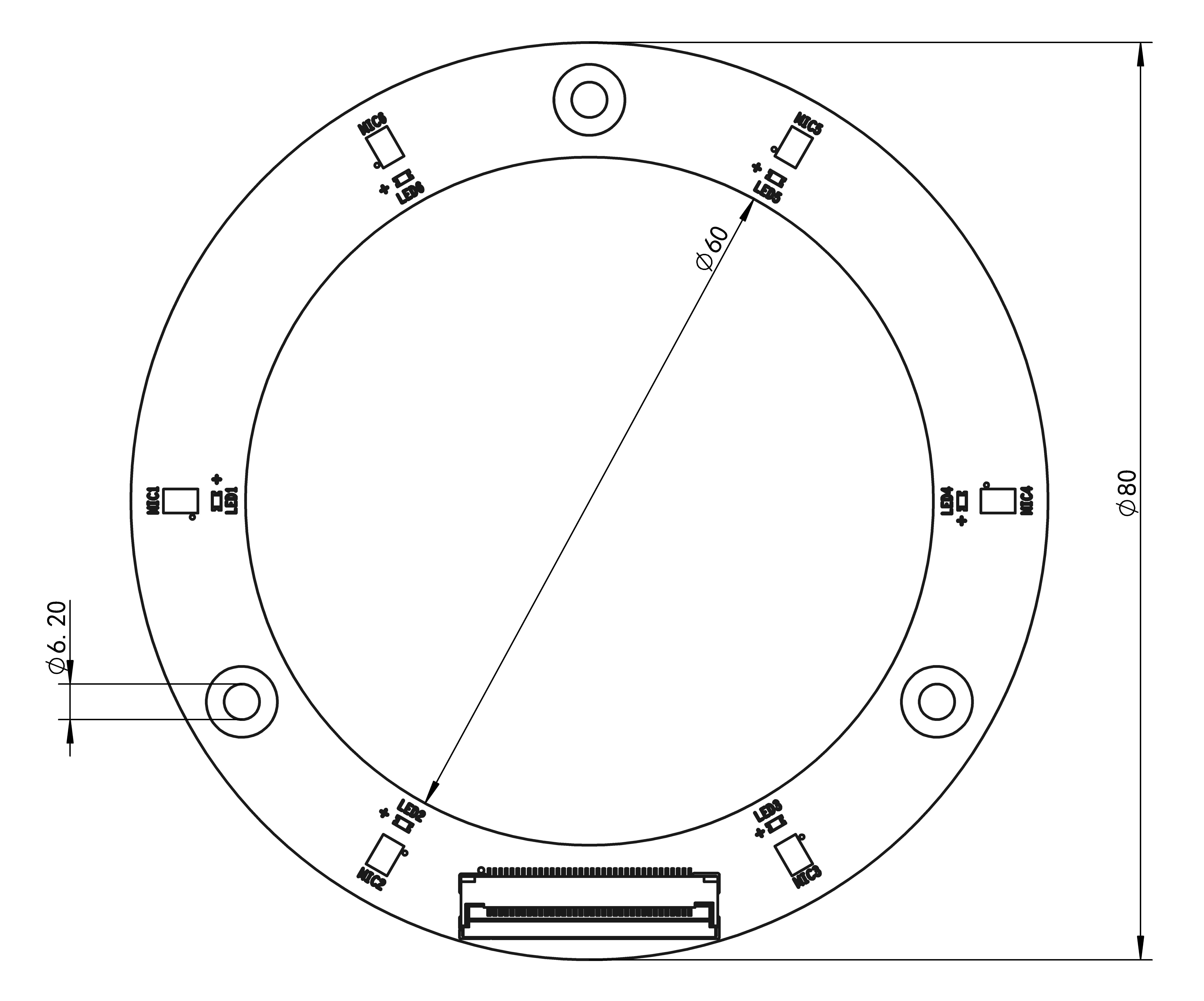
RDK Audio Expansion Board 6-Mic Array
The RDK Audio Expansion Board 6-Mic Array has 3 plated mounting holes, and can be secured with 3 × M6 screws.
- When mounting, use washers where appropriate and tighten the screws alternately to avoid cracking the PCB and damaging the product.
- If the mic array or speakers need to be installed into a sealed enclosure, design the sound-guiding structure yourself based on the actual situation to avoid affecting recording or playback quality.
- For the 3D model files, see Downloads.
Hardware interface description
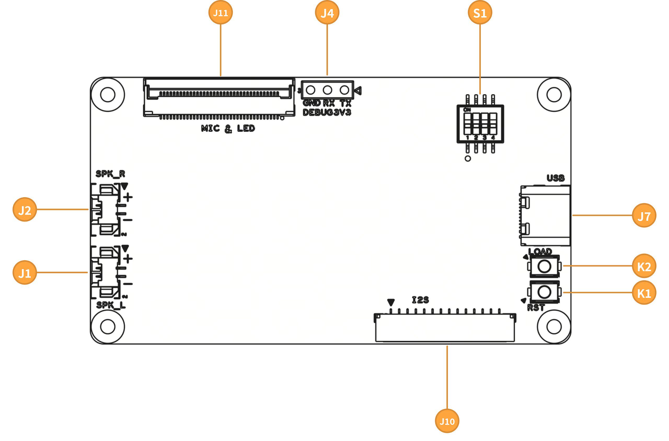
Interface description
J1 left-channel amplifier interface
This interface connects a left-channel speaker and outputs left-channel audio through a differential signal. The differential polarity corresponds to the PCB silkscreen.
J2 right-channel amplifier interface
This interface connects a right-channel speaker and outputs right-channel audio through a differential signal. The differential polarity corresponds to the PCB silkscreen.
J4 debug UART
This interface is for internal debugging and should be avoided in daily use.
J7 USB interface
Used for flashing the expansion board firmware and for USB audio (UAC) functionality.
J10 audio digital interface
This interface breaks out the I2S and I2C signals to connect the RDK Audio Expansion Board Adapter or an RDK development board.
The connector PIN1 position matches the Mark point. The pinout is shown in the table below:
| PIN | Name | Description |
|---|---|---|
| 1 | OUTCON_MCLK | MCLK signal of the audio Codec. |
| 2 | OUTCON_BCLK | BCLK signal of the audio Codec, used to synchronize serial audio data transmission. |
| 3 | OUTCON_WS | WS/LRCK signal of the audio Codec, used for I2S frame synchronization (left/right channel selection). Its frequency equals the audio sample rate. |
| 4 | OUTCON_SDIN | Connects to the DIN pin of the DAC. I2S serial data input, used for audio playback. |
| 5 | OUTCON_SDOUT1 | Connects to the DOUT pin of the ADC. I2S serial data output, used for capturing microphone audio. |
| 6 | OUTCON_MCLK2 | MCLK signal of the audio Codec. |
| 7 | OUTCON_BCLK2 | BCLK signal of the audio Codec, used to synchronize serial audio data transmission. |
| 8 | OUTCON_WS2 | WS/LRCK signal of the audio Codec, used for I2S frame synchronization (left/right channel selection). Its frequency equals the audio sample rate. |
| 9 | N/A | |
| 10 | OUTCON_SDOUT2 | Connects to the DOUT pin of the ADC. I2S serial data output, used for capturing microphone audio. |
| 11 | OUTCON_I2C_SDA | I2C data signal. |
| 12 | OUTCON_I2C_CLK | I2C clock signal. |
| 13 | GND | |
| 14 | VCC_IN | Power supply, 4.5V-5.5V |
The audio interface selector switch can set the audio kit to single-channel or dual-channel I2S mode:
- In single-channel I2S mode, PIN 6-10 are invalid, and audio signals are transmitted full-duplex through PIN 1~5. However, when sampling and output are performed simultaneously, the sampling channel and output channel must be at the same sample rate.
- In dual-channel I2S mode, audio signals are output simplex through PIN 1~4 and sampled simplex through PIN 6-10. In this mode, the sampling channel and output channel can be at different sample rates.
J11 microphone array interface
This interface connects the RDK audio core board to the RDK 4-Mic or 6-Mic array.
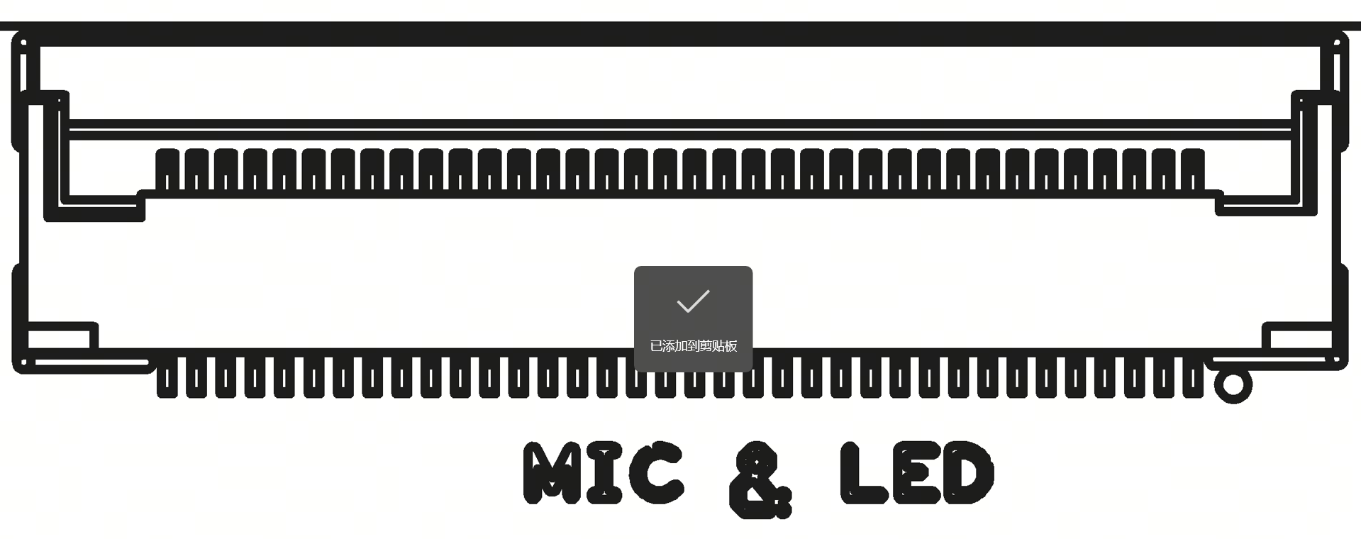
The connector PIN1 position is near the Mark point (rightmost). The pinout is shown in the table below:
| PIN | Name | Description |
|---|---|---|
| 1 | LED1+ | |
| 2 | LED1- | |
| 3 | LED2+ | |
| 4 | LED2- | |
| 5 | LED3+ | |
| 6 | LED3- | |
| 7 | LED4+ | |
| 8 | LED4- | |
| 9 | LED5+ | |
| 10 | LED5- | |
| 11 | LED6+ | |
| 12 | LED6- | |
| 13 | MIC1N_B | Mic differential signal output |
| 14 | MIC1P_B | Mic differential signal output |
| 15 | MICBIAS1_B | Mic bias voltage |
| 16 | AGND | |
| 17 | MIC2P_B | Mic differential signal output |
| 18 | MIC2N_B | Mic differential signal output |
| 19 | MICBIAS2_B | Mic bias voltage |
| 20 | AGND | |
| 21 | MIC1N_A | Mic differential signal output |
| 22 | MIC1P_A | Mic differential signal output |
| 23 | MICBIAS1_A | Mic bias voltage |
| 24 | AGND | |
| 25 | MIC2P_A | Mic differential signal output |
| 26 | MIC2N_A | Mic differential signal output |
| 27 | MICBIAS2_A | Mic bias voltage |
| 28 | AGND | |
| 29 | MIC3N_A | Mic differential signal output |
| 30 | MIC3P_A | Mic differential signal output |
| 31 | MICBIAS3_A | Mic bias voltage |
| 32 | AGND | |
| 33 | MIC4P_A | Mic differential signal output |
| 34 | MIC4N_A | Mic differential signal output |
| 35 | MICBIAS4_A | Mic bias voltage |
| 36 | AGND |
K1 RST button
This interface resets the audio kit state and should be avoided during normal use.
K2 LOAD button
This interface loads the debug mode of the audio board and should be avoided during normal use.
S1 audio interface selector switch
This interface is a 4-channel DIP switch used to select the audio interface, channel count, reference level, and other properties. The default state is as follows: all 4 channels are set to 0. Use tweezers to flip a channel up to set it to 1. The DIP switch state table is shown below:

| PIN | Name | Description |
|---|---|---|
| 1 | USB/I2S selection | 0: USB mode 1: I2S mode |
| 2 | I2S channel count selection | 0: single-channel 1: dual-channel (for the audio interface of RDK S600) |
| 3 | I2S level selection | 0: 1.8V 1: 3.3V |
| 4 | N/A |
Connector models
| Connector | Connector Model | Manufacturer |
|---|---|---|
| J1, J2 | HC-1.25-2PWT | - |
| J10 | X1251WRS-14HF-LPSW | XKB Connection |