1.8.2.1 Pin Definition and Application
The development board features expansion pin headers, allowing users to perform peripheral expansions. Refer to this chapter for interface definitions.
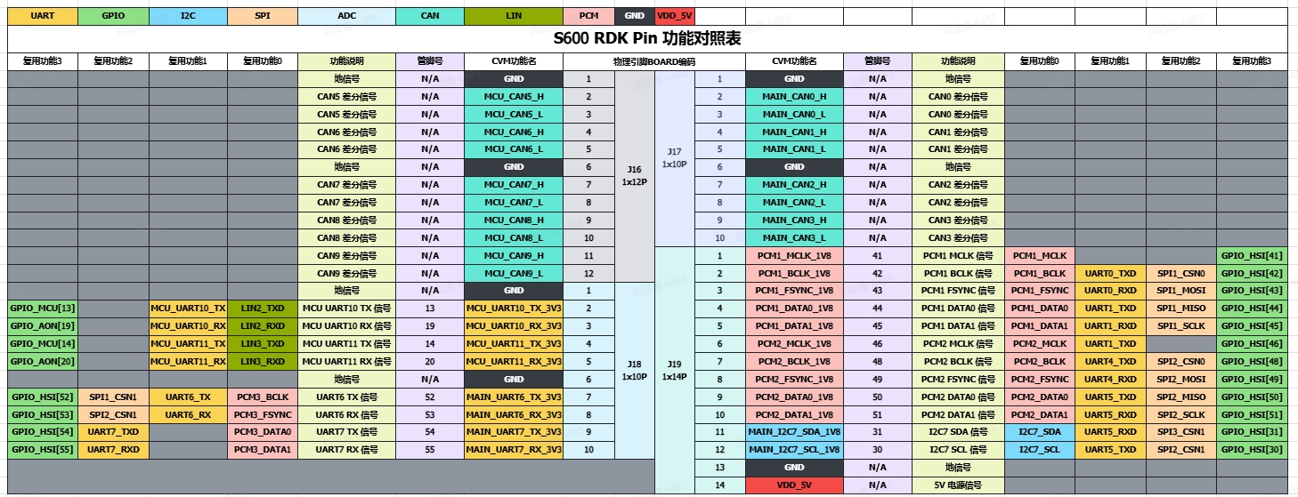
Expansion Pin Header Definition
The RDKS600 has two 10-pin self-locking interfaces, one 12-pin self-locking interface, and one 14-pin self-locking interface, making it convenient for users to expand peripherals. The digital I/O is designed with a 1.8V logic level. The interface definitions are as follows:
GPIO Read/Write Operation Example
The pins mentioned below are for illustrative purposes only. Port values may vary across different platforms, and actual conditions should prevail. You may also directly use the code in the /app/40pin_samples/ directory, which has been verified on the board.
In the development board's /app/40pin_samples/ directory, various functional test codes for PIN pins are pre-installed, including GPIO input/output tests, I2C, SPI, UART, and other tests. All test programs are written in Python. Refer to other sections of this chapter for more details.
Take /app/40pin_samples/button_led.py as an example. This program configures pin 4 as input and pin 3 as output, controlling the output state of pin 3 based on the input state of pin 4.
Environment Setup
Use a jumper wire to connect pin 4 to 1.8V or GND to control its high/low logic level.
How to Run
Execute the button_led.py program to start the GPIO read/write program.
root@ubuntu:~# cd /app/40pin_samples/
root@ubuntu:/app/40pin_samples# sudo python3 ./button_led.py
Expected Outcome
By controlling the high/low logic level of pin 4, you can change the output logic level of pin 3.
root@ubuntu:/app/40pin_samples# ./button_led.py
Starting demo now! Press CTRL+C to exit
Outputting 1 to Pin 3
Outputting 0 to Pin 3
Outputting 1 to Pin 3