6.6.1. Post-training Quantization (PTQ) FAQ
6.6.1.1. How to understand the two forms of BPU acceleration and CPU computation mentioned in the operator constraint?
BPU acceleration: It means that the operator can be quantized and accelerated by BPU hardware when the model is inferred at the board side, where most of the operators ( such as conv, and so on) are directly supported by the hardware. Some will be replaced with other operators to achieve acceleration (e.g., gemm will be replaced with conv); and others depend on specific contexts (e.g., Reshape, Transpose need to be BPU operators before and after) to be quantized passively.
CPU computation: For operators in the model that cannot be directly or indirectly accelerated by the BPU hardware, our toolchain will put them on the CPU for computation, and the runtime prediction library will also automatically complete the heterogeneous scheduling of the execution hardware during model inference.
6.6.1.2. How does model segmentation affect the performance?
When the model has CPU operators that cannot be accelerated in the middle of BPU operators, it is sliced into different Subgraphs (which will be distinguished by different id numbers in the model conversion log), thus introducing a certain performance loss in two ways.
CPU operator performance is much lower than that of the BPU operator.
The heterogeneous scheduling between CPU and BPU also introduces quantization and inverse quantization operators (running on CPU), and because the internal computation needs to traverse the data, its time consumption will be proportional to the shape size.
The above CPU operator and quantization and inverse quantization operators can be measured by passing profile_path parameter through the board-side tool hrt_model_exec. D-Robotics recommends that you try to build the model with BPU operator to get better performance.
6.6.1.3. Why some OPs supported by BPU at the tail part of the model running on CPU?
First, we need to understand the following two concepts:
The X5 algorithm toolchain currently supports only the Conv operator at the tail of the model to be output with int32 high precision, while all other operators can only be output with int8 low accuracy.
Normally, the model conversion will fuse Conv with its subsequent BN and ReLU/ReLU6 in the optimization stage for calculation. However, due to the limitation of the BPU hardware itself, Conv, which is output with int32 high precision at the end of the model, does not support operator fusion.
Therefore, if the model is ended with Conv+ReLU/ReLU6, then to ensure the overall accuracy of the quantized model, the Conv will by default use int32 output, while the ReLU/ReLU6 will run on the CPU.
Similarly, the other tail-part OPs who run on the CPU are also because that the Conv OP needs higher-accuracy output.
However, D-Robotics supports configuring these operators with run_on_bpu in the yaml file to get better performance, but introduces some loss of accuracy.
6.6.1.4. How to understand D-Robotics’s default calibration method?
To reduce the user’s workload in debugging calibration solutions, D-Robotics provides a default auto-search strategy, whose current internal logic is as follows:
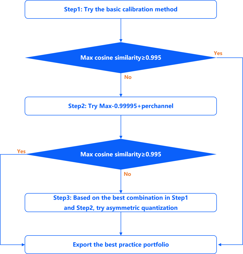
Step1: Try the Max, Max-Percentile 0.99995 and KL calibration methods to calculate the respective cosine similarity. If the highest cosine similarity among the three methods is less than 0.995, go to Step2; if not, return the threshold combination corresponding to the highest similarity.
Step2: Try the combination of Max-Percentile 0.99995 and perchannel quantization methods, if the highest cosine similarity is also less than 0.995, go to Step3. if not, return the threshold combination corresponding to the highest similarity.
Step3: Select the method corresponding to the highest cosine similarity in Step2, apply asymmetric quantization as the 5th method, and select the best solution among the 5 solutions according to the cosine similarity, return the corresponding threshold combinations.
6.6.1.5. How to understand D-Robotics’s mix calibration method?
To integrate the advantages of different calibration methods, D-Robotics offers a mix search strategy, which currently has the following internal logic:
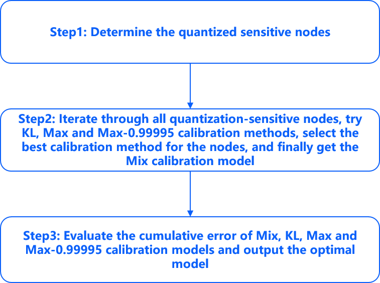
Step1: Determine the quantized sensitive nodes.
Step2: Iterate through all quantization-sensitive nodes, try KL, Max and Max-0.99995 calibration methods, select the best calibration method for the nodes, and then get the Mix calibration model.
Step3: Evaluate the cumulative error of Mix, KL, Max and Max-0.99995 calibration models and output the optimal model.
6.6.1.6. How to understand the compiler optimization level parameters in yaml files?
In the yaml configuration file of the model conversion, the compilation parameter group provides the optimize_level parameter to select the optimization level of the model compilation, the available range is O0~O3. Among which:
O0 without any optimization, the fastest compilation speed, suitable for use in model conversion function verification, debugging different calibration methods.
O3 is the highest optimization level, which can obtain the best performance of the model, but the compilation time is also relatively long.
In the range of O1 to O3, the higher the optimization level, the larger the search space will be when compiling the optimization. Also, some of the more time-consuming optimization strategies will be enabled only at the O2/O3 level.
The compiler’s optimization strategy is not at the operator granularity level, but is a global optimization for the whole model.
6.6.1.7. Why does the input size derived from the nv12 model hb_perf not match the prediction library?
The NV12 image format belongs to the YUV420SP format in the YUV color space, which is a video format that the camera can output directly. Since this format is not generally used in actual training, so the underlying hardware gets the camera output data and convert it to yuv444 format before the subsequent inference (the conversion process is not perceived by users, and the board-side inference only needs to prepare the corresponding type of data based on the input_type_rt configured during the model conversion). The hb_perf tool shows the size of the nv12 data (i.e. NxHxWx3/2), while the size of the data obtained by hrt_model_exec model_info on the board side is the real input data size of the model (i.e. NxHxWx3). Since nv12 data no longer has the concept of channel, you only need to prepare the corresponding size of nv12 data according to the H and W information of the input node when deploying on the board side.
6.6.1.8. Is the data layout of the inputs to the quantized model and the on-board bin model necessarily the same?
The input data layout of the onnx model and the on-board bin model are not necessarily identical . The input data layout of .bin is aligned with input_layout_rt in the yaml configuration file, but the data layout of quanti.onnx is subject to change due to a variety of factors, e.g.,
When the input type rt of the model is set to nv12, input_source defaults to pyramid , and when the input is pyramid, the inputs of the quantization model quanti.onnx are all NHWC.
When input type rt is yuv444/rgb/bgr, input_source defaults to ddr, and the input of quantization model quanti.onnx is the same as the original floating point model.
In addition other scenarios may occur where ***.onnx is not lined up with the ***.bin input data.
Therefore, when you reason about ***.onnx on the PC side, it is recommended to use a visualization tool to check the input shape of the onnx model and prepare the corresponding data.
When you reason about the .bin model on the board side, you get the input shape of the .bin model based on the input_layout_rt configured at the time of conversion or using the tool hrt_model_exec model_info and the BPU SDK related API (hbDNNGetInputTensorProperties()).
When you use the same image to infer quanti.onnx and .bin and find that the output results are very different, it is recommended that you first troubleshoot the input data layout to see if it is correct.
6.6.1.9. How to compile to get a multi-batch model?
According to the original model type, we will discuss this issue by dividing it into dynamic input models and non-dynamic input models.
Note
The
input_batchparameter can only be used only for the model which first dimension of theinput_shapeis 1 (if the model has multiple inputs, the first dimension of theinput_shapeneeds to be 1 for all inputs), and only effective when the original onnx model itself supports multi-batch inference. This parameter only supports specifying a single value, which will act on all inputs of the model when the model has multiple inputs.The size of each calibration data shape should be the same as the size of
input_shape.
Dynamic input model: If the original model is a dynamic input model, for example, ? x3x224x224 (dynamic input models must use the input_shape parameter to specify the model input information).
1.When input_shape is configured as 1x3x224x224, if you want to compile the model to get a multi-batch model, you can use input_batch parameter, then each calibration data shape size is 1x3x224x224.
2.When the first dimension of input_shape is an integer greater than 1, the original model itself will be recognized as a multi-batch model, and the input_batch parameter can not be used, and you need to pay attention to the size of each calibration data shape. For example, if the input_shape is 4x3x224x224, the size of each calibration data shape need to be 4x3x224x224.
Non-dynamic input model.
1.When the input shape[0] of the input is 1, you can use the input_batch parameter. Each calibration data shape size is the same as the original model shape.
2.When the input shape[0] is not 1, the input_batch parameter is not supported.
6.6.1.10. Is it normal for the order of model inputs to change during the conversion of a multi-input model?
This is normal. It is possible for the model input order to change during the conversion of a multi-input model. The possible cases are shown in the following example.
original floating-point model input order: input1, input2, input3.
original.onnx model input order: input1, input2, input3.
quanti.onnx model input order: input2, input1, input3.
bin model input order: input3, input2, input1.
Attention
When you do accuracy consistency alignment, please make sure the input order is correct, otherwise it may affect the accuracy result.
If you want to check the bin model input order, you can use the
hb_model_infocommand to check it. The input order listed in the input_parameters info group is the bin model input order.