3. Basic Peripheral Usage
The development board file structure is as follows. In the /userdata/magicbox/basic_function_demo/ directory, basic peripheral usage examples are pre-installed. Executing these programs allows you to control the corresponding peripherals.
root@ubuntu:/userdata/magicbox# tree -L 2
.
├── app                                # Application function files
│   ├── ros_ws                         # ROS2 workspace, containing almost all application functions
│   └── Web_RDK_Performance_Node       # Resource monitoring application
|
├── basic_function_demo                # Basic peripheral usage examples (python)
│   ├── button.py                      # Button control script
│   ├── imu.py                         # IMU usage script
│   ├── servo.py                       # Servo control script
│   └── ws2812b.py                     # LED strip control script
|
├── config                             # Configuration files for the app
│   └── ......
├── dep                                # Third-party packages required by the app
│   ├── llama.cpp                      # llama.cpp
│   ├── matcha-icefall-zh-baker        # Dependency for TTS voice model
│   └── sherpa-onnx                    # sherpa-onnx
|
├── launch                             # Files related to launching functions
│   ├── lamp                           # Light control scripts required for startup
│   ├── start.py                       # Control script for starting and stopping all application functions
│   └── start.sh                       # Script executed during auto-start
|
├── log                                # Log files
|
└── voice                              # Audio files
    ├── robot.mp3
    └── wakeup.mp3
Servo Control
Specifications
The servo model is PTK 7465 MG-D. For specific parameters, please refer to the official Technical Specifications.
PWM Description
- The servo is controlled via a PWM signal, connected to BOARD pins 32 and 33. For pin functions, see 40PIN Pin Definitions.
- For details on PWM usage and interface descriptions, please refer to the PWM Application Documentation.
Execution Script
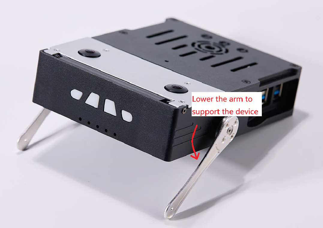
Use the following command to execute the built-in servo.py script: It is used to control the lowering of two rocker arms, touching the ground and lifting the body.
# Control the two rocker arms downward to lift the device, implemented based on PWM
python3 /userdata/magicbox/basic_function_demo/servo.py
Result Display
Light Control
Specifications
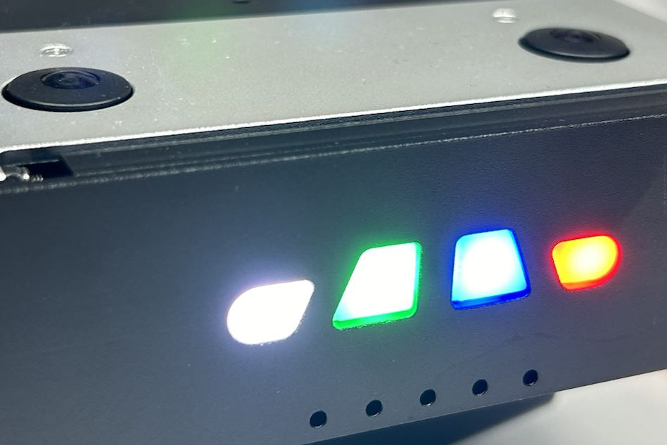
The LED model is WS2812B, supporting 24-bit full-color display.
Interface Description
- The four LED beads are controlled via the SPI interface, connected to device 0 on SPI bus 1.
- For details on SPI usage and interface descriptions, please refer to the SPI Application Documentation.
Execution Script
Use the following command to execute the built-in ws2812b.py script: It is used to control the LED beads to light up and display different colors.
# Control the device lights to light up and display different colors, implemented based on SPI
python3 /userdata/magicbox/basic_function_demo/ws2812b.py
Result Display
IMU Control
Specifications
The binocular camera comes with its own IMU. The RDK X5 MagicBox expansion board has a built-in IMU, model ICM20948.
IMU Communication Description
- Communication with the onboard IMU is via I2C bus 5, using smbus2 to implement control logic.
- For details on I2C usage and interface descriptions, please refer to the I2C Application Documentation.
Execution Script
Use the following command to execute the built-in imu.py script: Run the IMU and print data.
# Run the IMU, print data, implemented based on smbus2
python3 /userdata/magicbox/basic_function_demo/imu.py
Result Display

Button Control
Logic Description
-
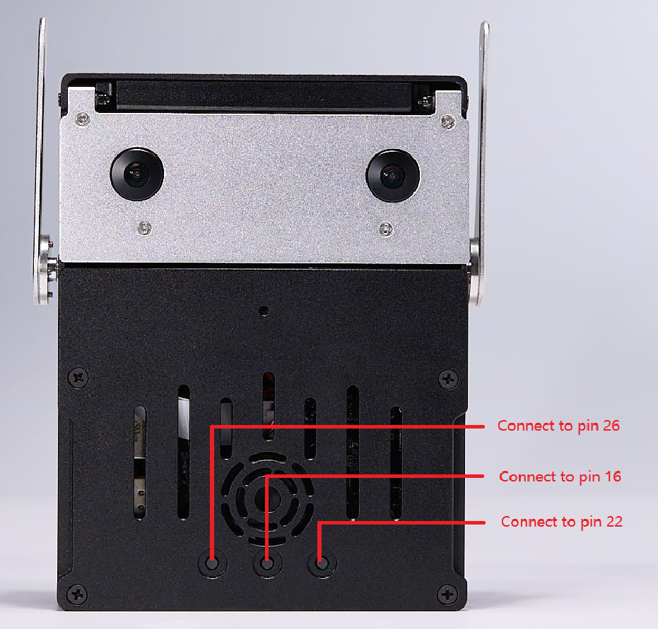
The button logic is implemented via GPIO, connected to BCM pins 22, 16, and 26. For detailed pin information, see 40PIN Pin Definitions.
-
Pressing the button triggers a low level, and
GPIO.FALLINGis used to detect the press event. -
For details on GPIO usage and interface descriptions, please refer to the GPIO Application Documentation.
Execution Script
Use the following command to execute the built-in button.py script: Outputs button press feedback, printing button1 OK, button2 OK, button3 OK when the button is pressed.
# Run button press feedback. Press the button to print button1 OK/button2 OK/button3 OK, implemented based on GPIO
python3 /userdata/magicbox/basic_function_demo/button.py
Microphone and Speaker Usage
Specifications
- Microphone model: INMP441
- Amplifier model: NS4168
Interface Description
The microphone and speaker are connected via the I2S interface, with the device number hw:0, 0.
Usage Commands
Use the following commands to control the microphone and speaker:
# Microphone recording
arecord -D plughw:0,0 -c 1 -r 16000 -f S16_LE -t wav -d 5 record1.wav
# Speaker playback
aplay -D plughw:0,0 record1.wav
# MP3 playback
mpg123 -a hw:0,0 /userdata/magicbox/voice/wakeup.mp3