Pin Definition and Application
For the interface definitions of the 40PIN functional pins on the development board, please refer to this section.
Hardware Usage Instructions
- The 40PIN interface on the RDK provides GPIOs with 3.3V logic signals, and the maximum withstand voltage is 3.46V.
- For the 40PIN interface on the RDK, the 3.3V output supports a maximum of 800mA, and the 5V output supports a maximum of 500mA. Under the above maximum output currents, the input adapter for the RDK must support a minimum load capacity of 25W.
- When connecting peripherals, strict attention should be paid to the power, ground, and signal levels on the 40PIN interface. Any overvoltage, overcurrent, ESD, or similar events may cause irreversible damage to the RDK.
- When using jumper wires to connect the RDK and other functional boards, ensure that the RDK product is powered off and shut down.
Pin Multiplexing Configuration
The 40PIN pins will have dedicated functions such as UART, SPI, I2C, and I2S enabled by default as shown in this section. If you need to configure specific pins as GPIO functions, you must do so using the srpi-config configuration tool.
Note that the srpi-config program needs to be run in a full-screen command line window as follows:
sudo srpi-config
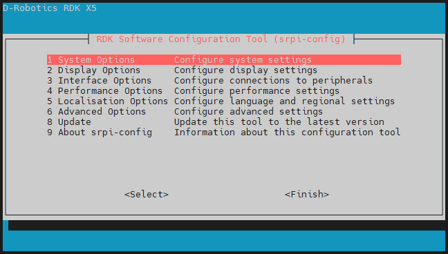
Select 3 Interface Options -> I3 Peripheral bus config to enter the following bus configuration interface.
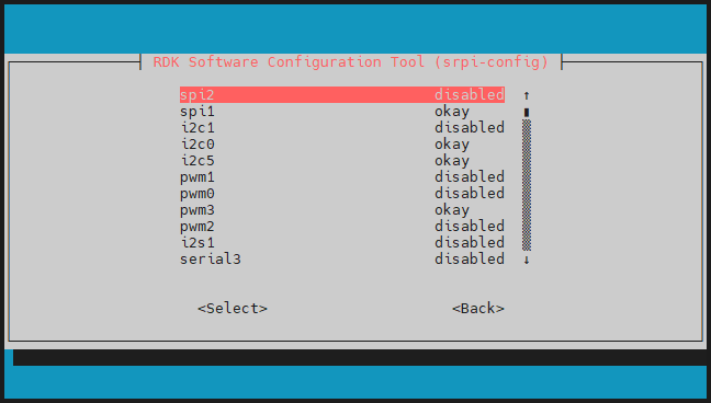
On the RDK X5, some interfaces have multiplexing relationships.
In the same set of multiplexed functions, only one function will take effect when enabled.
When all multiplexed functions are disabled, the interface will behave as a regular GPIO function.
Examples of multiplexed functions are as follows:
| Interface Function 1 | Interface Function 2 |
|---|---|
| uart3 | i2c5 |
| i2c0 | pwm2 |
| spi2 | pwm0 |
| spi2 | pwm1 |
| i2c1 | pwm3 |
okay configures the corresponding pin for a dedicated function, while disabled turns off the dedicated function for that pin, allowing it to be used as a GPIO. The configuration takes effect after a reboot.
- Use the up and down arrow keys to select a function item, and press Enter to toggle the function on/off.
- Use the left and right arrow keys to select Select and Exit, and press Enter to confirm.
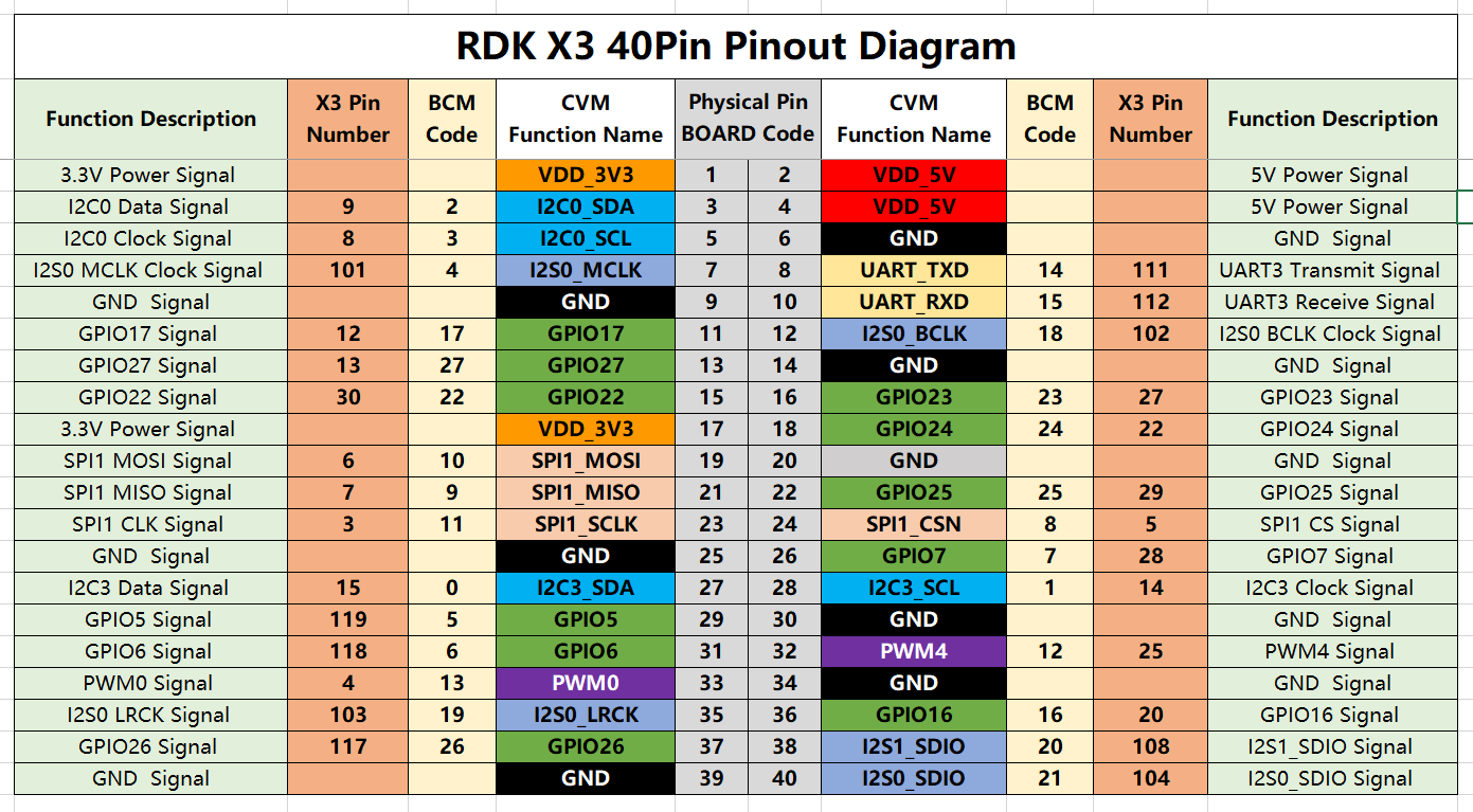
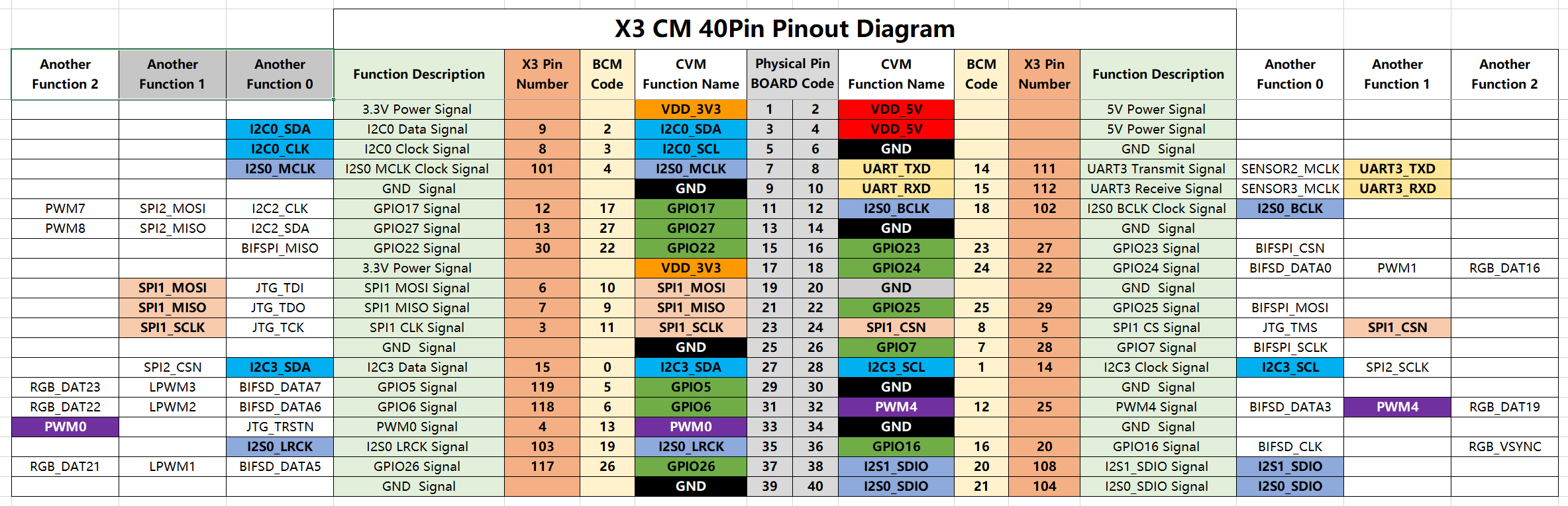
40PIN Pin Definition
The development board provides a 40PIN standard interface for easy peripheral expansion, with digital I/O using a 3.3V logic level. The 40PIN interface definition is as follows:
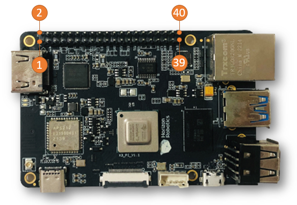
The 40PIN interface position on the development board is marked with a silkscreen netlist for easy reference. The positions of PIN1 and PIN40 are as follows:

GPIO Read/Write Operation Example
In the /app/40pin_samples/ directory of the development board, various functional test codes for the 40PIN pins are pre-installed, including GPIO input/output tests, PWM, I2C, SPI, UART, and more. All test programs are written in Python. For detailed information, please refer to other sections of this chapter.
Take /app/40pin_samples/button_led.py as an example. This program configures pin 37 as input and pin 31 as output, and controls the output state of pin 31 based on the input state of pin 37.
Environment Preparation
Use a jumper wire to connect pin 37 to 3.3V or GND to control its high/low level.
How to Run
Execute the button_led.py program to start the GPIO read/write program.
sunrise@ubuntu:~$ cd /app/40pin_samples/
sunrise@ubuntu:/app/40pin_samples$ sudo python3 ./button_led.py
Expected Outcome
By controlling the high/low level of pin 37, you can change the output level of pin 31.
sunrise@ubuntu:/app/40pin_samples$ sudo python3 ./button_led.py
Starting demo now! Press CTRL+C to exit
Outputting 0 to Pin 31
Outputting 1 to Pin 31
Outputting 0 to Pin 31