V4L2 Usage
RDK X5 supports the V4L2 interface. Users can access MIPI cameras on RDK X5 through the V4L2 interface and obtain image data from stages such as VIN, ISP, and VSE.
Background
HBN Framework
The HBN framework covers most modules in the Camera Sensor capture pipeline, including VIN, ISP, VSE, GDC, and N2D. Among these, VIN, ISP, and VSE can be accessed through the V4L2 interface.
| Module | Full Name | Description |
|---|---|---|
| VIN | Video Input | Software concept that includes MIPI and SIF; receives data from single or multiple Camera sensors and sends it directly to downstream ISP or writes to DDR |
| SIF | Sensor Interface | Connects to the MIPI port and sends frames received from the MIPI interface to downstream ISP or writes directly to DDR |
| ISP | Image Signal Processor | Image signal processor |
| VSE | Video Scaler | Image cropping, scaling, and color space conversion |
VIN is used for image capture. It can capture raw images from 4 SIF interfaces, typically in RAW format;
ISP (Image Signal Processor) is used for image signal processing. RDK X5 supports multiple sensors, all of which have completed ISP tuning. Processed NV12 format images can be obtained directly;
VSE (Video Scale Engine) is used for image scaling. It supports 6 scaling channels and can output processed NV12 format images. Channel characteristics are as follows:
-
Maximum processing capability: 3840x2160@60fps
-
Supports input cropping, scaling in horizontal and vertical directions separately, with independent processing of chrominance and luminance components
-
5 downscale channels
-
Maximum supported resolutions: 4K/1080P/1080P/720P/720P respectively
-
Minimum resolution is 64x64, supporting arbitrary downscale factors
-
1 upscale channel
-
Maximum supported resolution 4K, maximum upscale factor 4X, upscale factor range 0–4
Output Channel ID Type Channel Function 0 offline 4K Downscale 1 offline 1080P Downscale 2 offline 1080P Downscale 3 offline 720P Downscale 4 offline 720P Downscale 5 offline 4K Upscale
Mode Switching
Use srpi-config to configure the camera capture mode.
Go to 3 Interface Options → I7 V4L2.
Select I1 V4L2 Enable/disable V4L2 interface for camera.
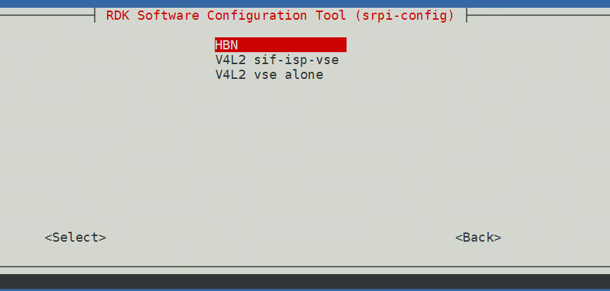
Mode Introduction
HBN Standard Mode
Camera uses a separate set of APIs. Modules after Camera are abstracted by vnode, including VIN, ISP, VSE, GDC, and Codec. Multiple vnodes form a vflow (similar to a pipeline). Camera and VIN are bound through the attach interface. Users only need to call HBN interfaces to complete module initialization and binding. After the vflow is established and started, users do not need to worry about frame transfer; the X5 internally passes frames from upstream to downstream.
V4L2 sif-isp-vse V4L2 Data Flow Mode
The camera is added through the V4L2 sensor driver. VIN, ISP, and VSE all provide corresponding V4L2 video device nodes. Users can directly obtain the corresponding data through the V4L2 API.
V4L2 vse alone V4L2 VSE Standalone Mode
Provides V4L2 video device nodes for VSE channels. Users can directly feed images back to the VSE module for processing through the V4L2 API.
Camera Configuration
If sif-isp-vse is selected, a CAM0/CAM1 camera selection dialog will appear.
On X5 RDK, cam0 is near the Ethernet port and cam1 is away from the Ethernet port;
On X5 MD, refer to the silkscreen on the carrier board;
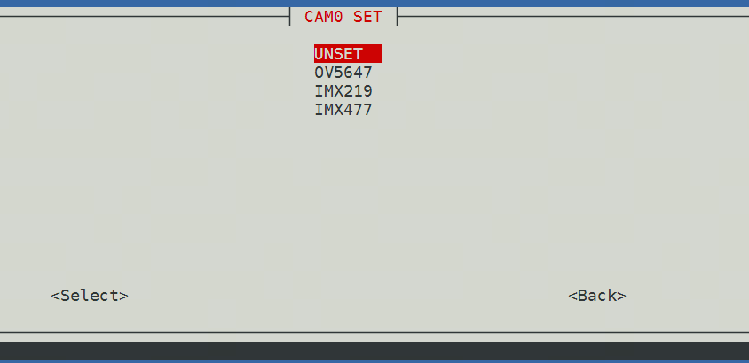
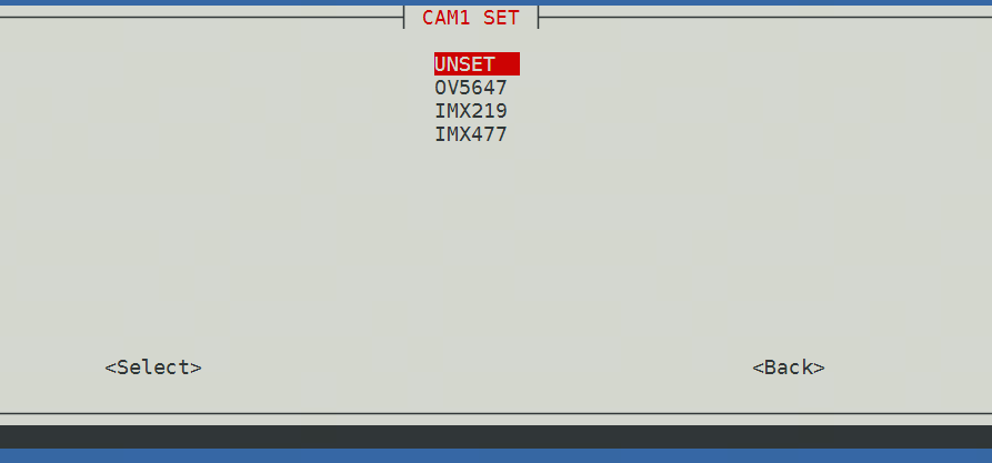
After configuration is complete, reboot the board;
Verify that V4L2 mode is active:
Use lsmod to check drivers. You should see V4L-related drivers and sensor-related drivers.
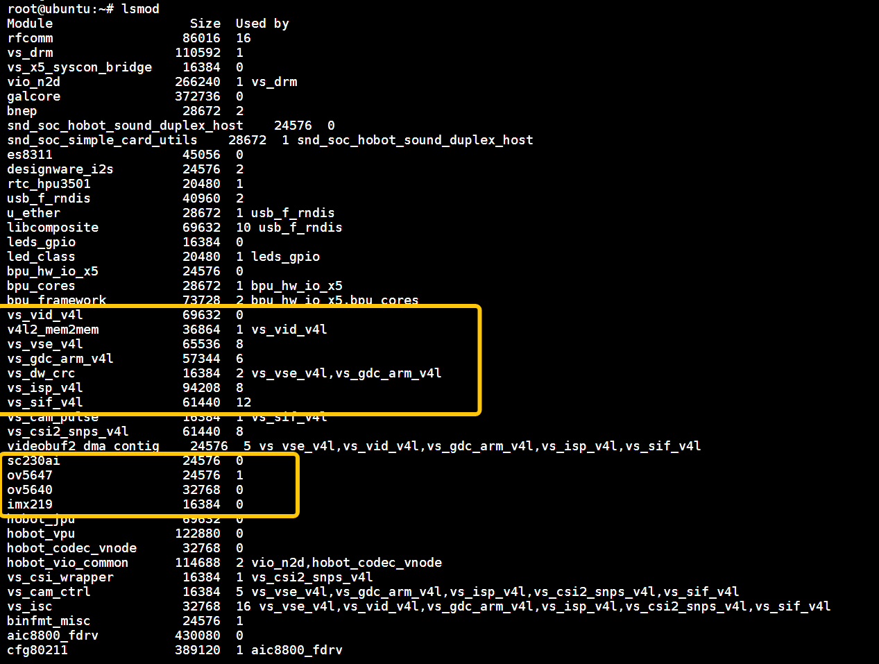
Device Topology
After V4L2 sif-isp-vse mode is active, you can use the following commands to view the device topology diagram. It shows the media pipeline structure of the /dev/media0 device, including sensors, ISP, video nodes, data flow paths, and other information.
media-ctl -d /dev/media0 --print-dot > media0.dot
dot -Tpng media0.dot -o media0.png

You can also look up the mapping in the table below:
VIDEO_DEV_CSI0_SIF "/dev/video0"
VIDEO_DEV_CSI0_ISP "/dev/video4"
VIDEO_DEV_CSI0_VSE0 "/dev/video8"
VIDEO_DEV_CSI0_VSE1 "/dev/video9"
VIDEO_DEV_CSI0_VSE2 "/dev/video10"
VIDEO_DEV_CSI0_VSE3 "/dev/video11"
VIDEO_DEV_CSI0_VSE4 "/dev/video12"
VIDEO_DEV_CSI0_VSE5 "/dev/video13"

VIDEO_DEV_CSI1_SIF "/dev/video1"
VIDEO_DEV_CSI1_ISP "/dev/video5"
VIDEO_DEV_CSI1_VSE0 "/dev/video14"
VIDEO_DEV_CSI1_VSE1 "/dev/video15"
VIDEO_DEV_CSI1_VSE2 "/dev/video16"
VIDEO_DEV_CSI1_VSE3 "/dev/video17"
VIDEO_DEV_CSI1_VSE4 "/dev/video18"
VIDEO_DEV_CSI1_VSE5 "/dev/video19"

VIDEO_DEV_CSI2_SIF "/dev/video2"
VIDEO_DEV_CSI2_ISP "/dev/video6"
VIDEO_DEV_CSI2_VSE0 "/dev/video20"
VIDEO_DEV_CSI2_VSE1 "/dev/video21"
VIDEO_DEV_CSI2_VSE2 "/dev/video22"
VIDEO_DEV_CSI2_VSE3 "/dev/video23"
VIDEO_DEV_CSI2_VSE4 "/dev/video24"
VIDEO_DEV_CSI2_VSE5 "/dev/video25"

VIDEO_DEV_CSI3_SIF "/dev/video3"
VIDEO_DEV_CSI3_ISP "/dev/video7"
VIDEO_DEV_CSI3_VSE0 "/dev/video26"
VIDEO_DEV_CSI3_VSE1 "/dev/video27"
VIDEO_DEV_CSI3_VSE2 "/dev/video28"
VIDEO_DEV_CSI3_VSE3 "/dev/video29"
VIDEO_DEV_CSI3_VSE4 "/dev/video30"
VIDEO_DEV_CSI3_VSE5 "/dev/video31"
For RDK boards, the topology can be simplified as follows:

Usage Instructions
V4L2-CTL Commands
- Use
v4l2-ctl --list-formats-extto query supported resolutions and encoding formats; this also allows the driver to complete initialization; - Use
v4l2-ctl -d /dev/video4to capture video data;
v4l2-ctl --list-formats-ext --device /dev/video4
v4l2-ctl -d /dev/video4 \
        --set-fmt-video=width=640,height=480,pixelformat=NV12 \
        --stream-mmap=3 \
        --stream-skip=3 \
--stream-to=/tmp/nv12.yuv \
        --stream-count=1 \
        --stream-poll
V4L2 Sample Code
Sample code is provided as source code. Compile with make before running:
cd /app/cdev_demo/v4l2/
sudo make
Parameter Description
-w sensor output width
-h sensor output height
-c number of frames to capture
-n sensor capture video node
-o input NV12 image video node
-i input NV12 image path
- In
V4L2 sif-isp-vsemode, capture images and save to file
./v4l2 -w 1920 -h 1080 -c 10 -n 4
- In
V4L2 vse alonemode, use the VSE node standalone with1080p.yuvas the input image and save the scaled images to file
./v4l2 -w 1920 -h 1080 -c 10 -n 2 -o 2 -i ./1080p.yuv
Multimedia Applications
Both hbn mode and V4L2 sif-isp-vse mode use the same set of sample programs. hobot-spdev automatically selects the working mode based on the current driver. The printed information differs slightly between the two modes.
Multimedia samples automatically select the camera based on srpi-config configuration. Please ensure the camera configuration is correct. If both cam0 and cam1 are configured, cam1 is selected by default.
Supported Sample Programs
For HDMI display, stop the desktop first:
sudo systemctl stop lightdm
/app/cdev_demo/vio2display
/app/cdev_demo/vio_capture
/app/cdev_demo/vio2encoder
/app/cdev_demo/bpu ./sample -f /app/model/basic/yolov5s_672x672_nv12.bin -m 0
/app/pydev_demo/03_mipi_camera_sample
Known Issues
- When capturing VSE streams, the ISP sensor configuration file with 1920x1080 resolution must be selected;
- In
V4L2 vse alonemode, only VSE channel 2 is supported for image feed-in and obtaining processed results;