Hardware Reference
Mechanical Installation
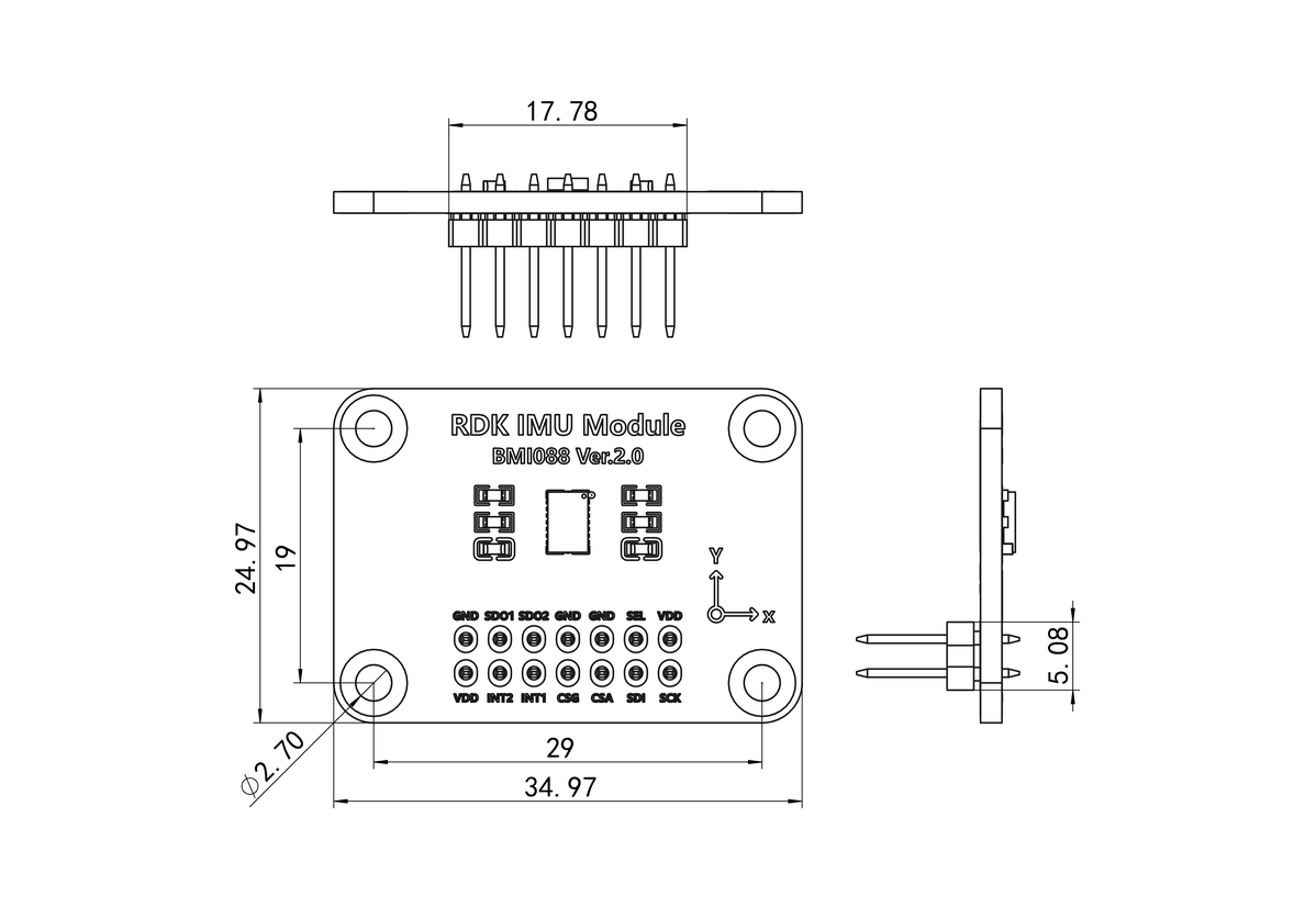
The RDK IMU core board has one 2×7 pin header and four mounting holes. It connects to the 2×7 socket on the carrier board and can be secured with four M2.5×11 standoffs and screws, or a custom support structure. Core board dimensions (unit: mm):
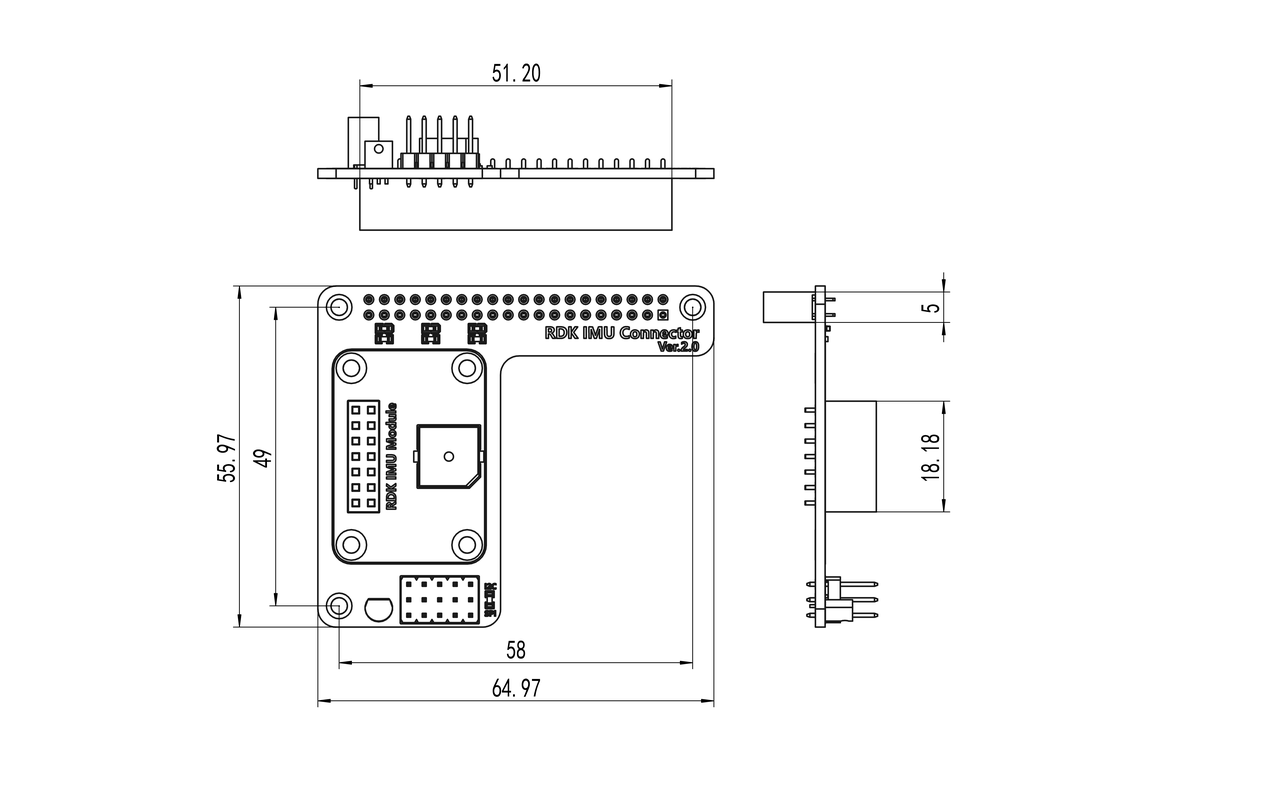
The carrier board has one 2×7 socket and four mounting holes for the core board, plus one 40-pin socket and three mounting holes for the development board. It can be secured with three M2.5×11 standoffs and screws, or a custom support structure. Carrier board dimensions (unit: mm):
Hardware Interface Reference
Topology
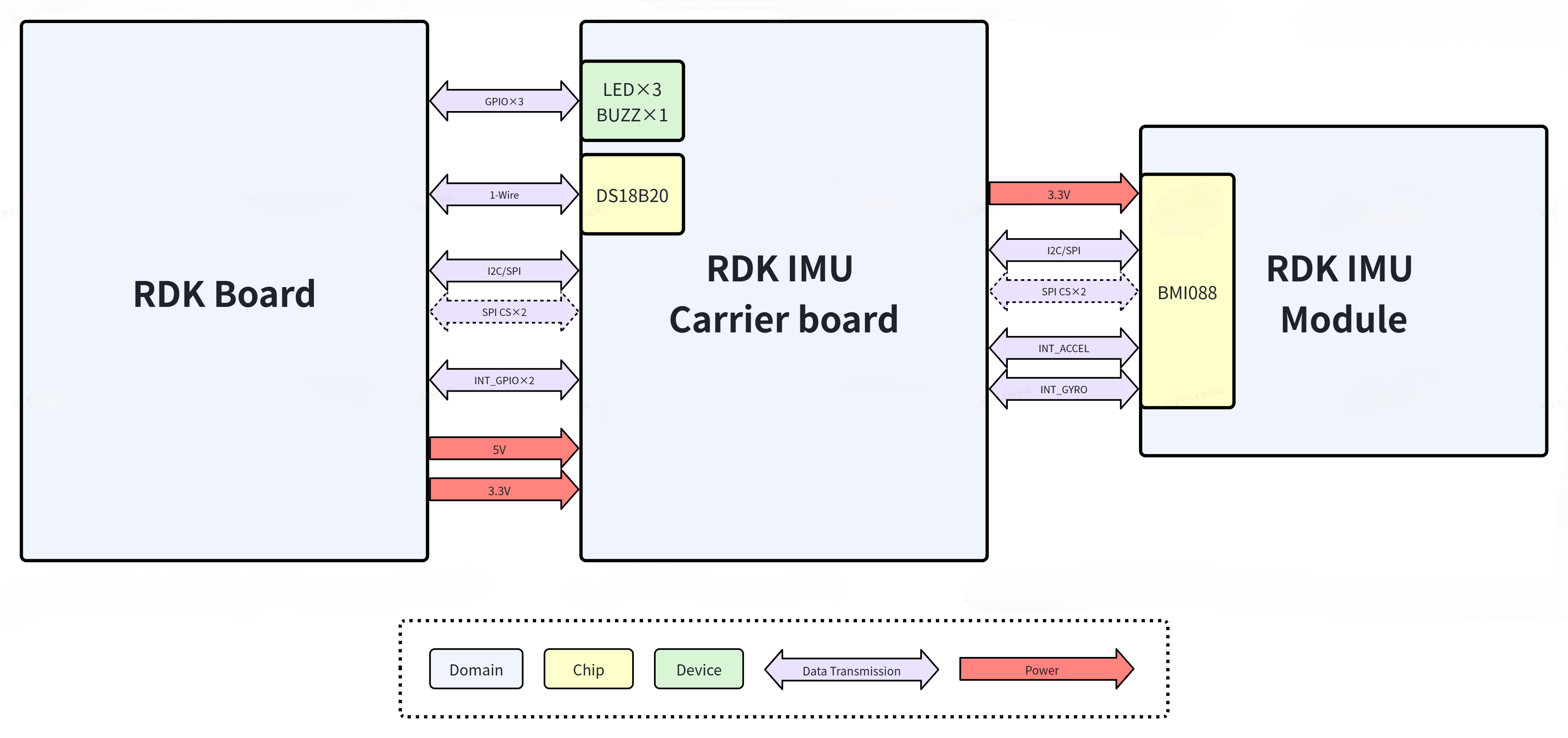
The diagram below shows the hardware topology between the RDK IMU Module and an RDK development board.
Component List
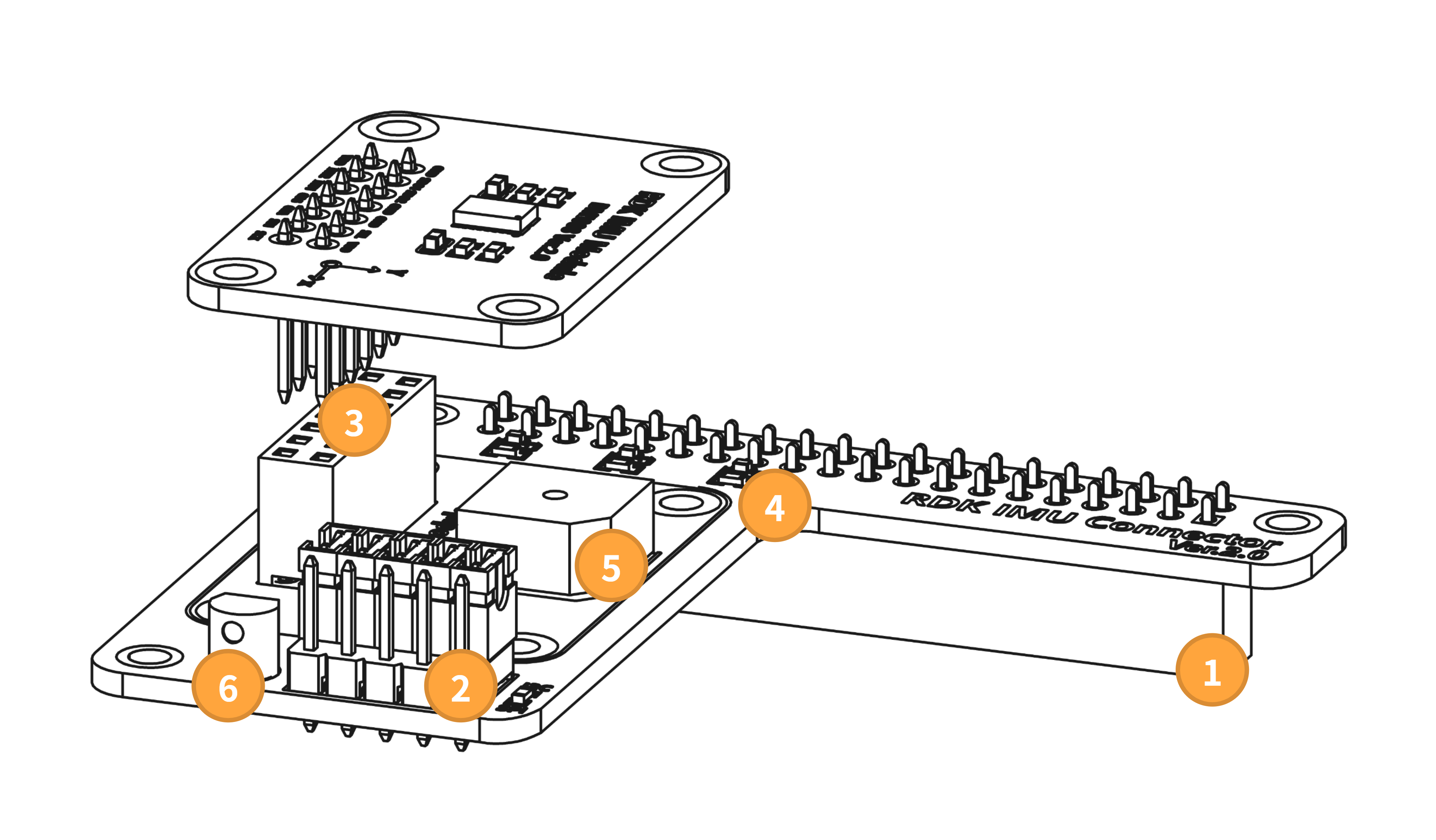
| Ref | Component |
|---|---|
| 1 | 2.54 mm, 2×20P socket |
| 2 | 2.54 mm, 3×5P pin header |
| 3 | 2.54 mm, 2×7P pin header & socket |
| 4 | 0603 LED R/G/B |
| 5 | YS-SBZ9650DYB05 |
| 6 | DS18B20 |
Interface Description
40-Pin Header
This interface connects to the development board 40-pin header and is the only link between the IMU module and the board.
Pin 1 matches the RDK X5 definition. Pin assignment:
| Desc | Name | Pin | Pin | Name | Desc |
|---|---|---|---|---|---|
| 3V3 | 1 | 2 | 5V | ||
| Used for SPI/I2C | SDA/SDI | 3 | 4 | 5V | |
| Used for SPI/I2C | SCL/SCK | 5 | 6 | N/A | |
| N/A | 7 | 8 | N/A | ||
| Ground | GND | 9 | 10 | N/A | |
| LED | 11 | 12 | N/A | ||
| LED | 13 | 14 | N/A | ||
| LED | 15 | 16 | N/A | ||
| 3V3 | 17 | 18 | N/A | ||
| Used for SPI/I2C | SDA/SDI | 19 | 20 | N/A | |
| Used for SPI | SDO | 21 | 22 | N/A | |
| Used for SPI/I2C | SCL/SCK | 23 | 24 | CS_ACCEL | Used for SPI |
| Ground | GND | 25 | 26 | CS_GYRO | Used for SPI |
| N/A | 27 | 28 | N/A | ||
| N/A | 29 | 30 | N/A | ||
| BUZZ | 31 | 32 | N/A | ||
| N/A | 33 | 34 | N/A | ||
| N/A | 35 | 36 | INT1 | Used for Interrupt | |
| Connect DS18B20 | DQ | 37 | 38 | INT3 | Used for Interrupt |
| GND | 39 | 40 | N/A |
Communication Mode Selector
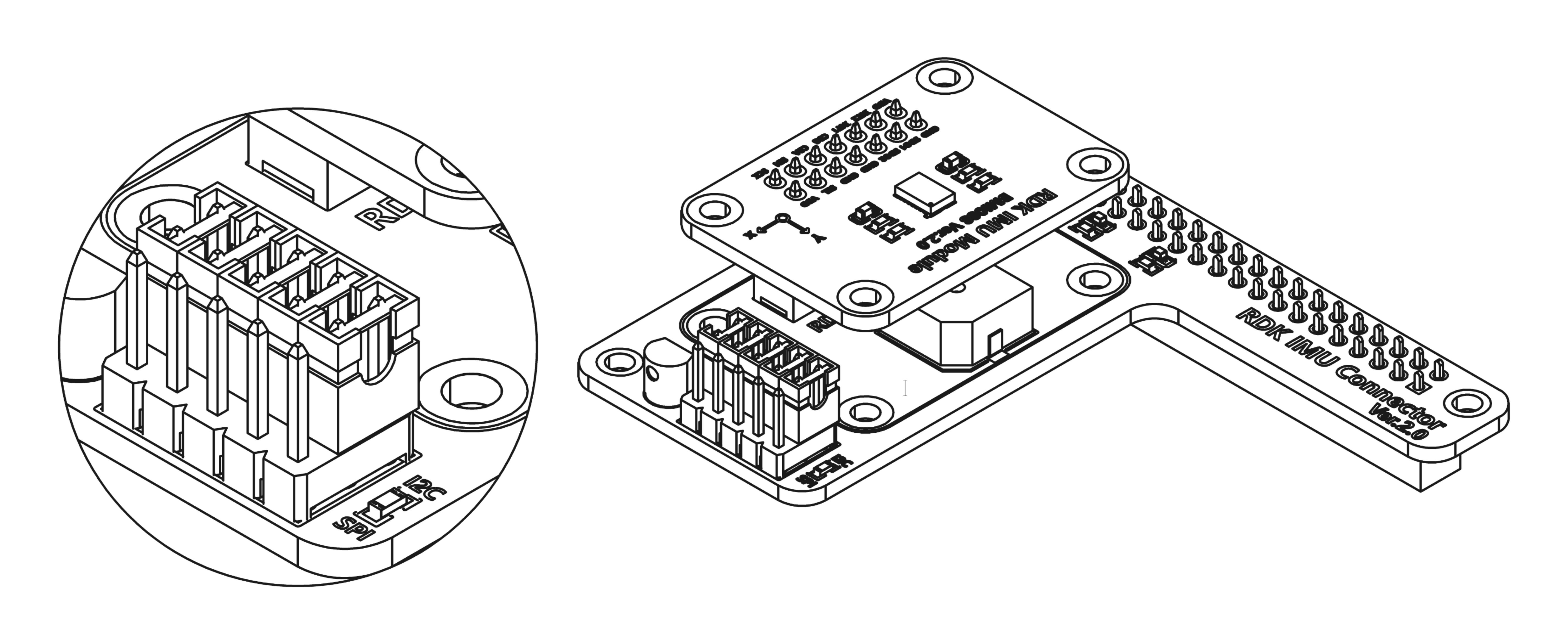
Use this interface to switch the module communication mode. Connect the center 5-pin header to the five pins labeled I2C with jumper caps to select I2C, as shown:
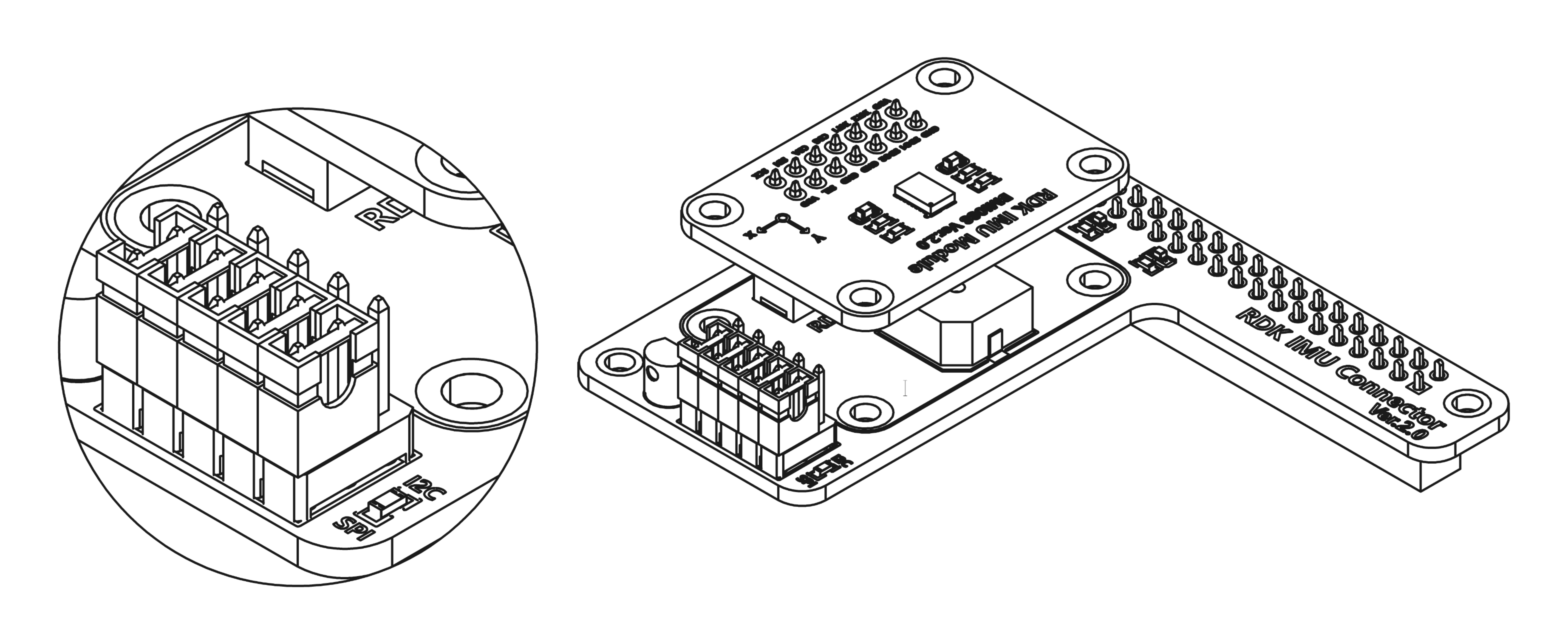
Connect the center 5-pin header to the five pins labeled SPI to select SPI, as shown:
IMU Core Board Connector
Connects the IMU core board to the carrier board.
Indicator LEDs
The carrier board has three LEDs for status indication, driven via 40-pin GPIO.
Buzzer
The carrier board has an active buzzer for status indication.
Temperature Sensor
The carrier board includes a DS18B20 temperature sensor on the 1-Wire bus for ambient or carrier board temperature measurement.